Modeling and simulation of Load Frequency Control in Automatic
Generation Control using Genetic Algorithms
Technique
Vikas JainP
1
P
, Naveen senP
2
P
, Kapil ParikhP
3
P
1
P
(MTECH Student, Power system, Pacific University, Udaipur)
P
2
P
(Assistant Professor, EE Department, Pacific University, Udaipur)
P
3
P
(Assistant Professor, EE Department, SITE, Nathdwara)
ABSTRACT-
The automatic generation control (AGC) process performs the task of adjusting system generation to meet the load demand and regulating at the large system frequency changes. In most of the previous works on interconnected systems, tie-line bias control strategy has been widely accepted by utilities. In this method, area control error (ACE) is calculated through feedback for each area and control action is taken to regulate ACE to zero. The problems of frequency control of interconnected areas are more important than those of isolated (single) areas.
Practically all power systems today are tied together with neighboring areas and the problem of automatic generation control becomes a joint undertaking. Consequently secure, economic and stable operation of a power system requires improved and innovative methods of control. Intelligent control techniques provide a high adoption to changing conditions and have ability to make decisions quickly by processing imprecise information. Some of these techniques are rule based logic programming; model based reasoning and computational approaches like Particle swarm optimization , genetic algorithms ,fuzzy sets, artificial neural networks, evolutionary programming. In this research work, the genetic algorithms controlling technique has been used for AGC of interconnected power systems. The effectiveness of the genetic algorithms is tested on a double machine generating system operating with AGC for several of operating points. These systems are comparing for without and with genetic algorithms. This comparison shows that genetic algorithms give efficient output.
Keywords-
ACE,
AGC, LFC, GA methodI.
INTRODUCTION
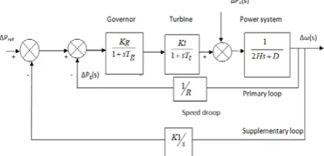
Maintaining power system frequency at constant value is very important for the protection of the power generating equipment and the utilization equipment at the customer end. The job of automatic frequency regulation is achieved by governing systems of individual turbine-generators and automatic generation control (AGC) or load frequency control (LFC) system of the power system.
Fig. 1. A two area interconnected power system
II.
OBJECTIVE FUNCTION
The objective of the thesis is to use the PSO algorithm in order to obtain optimal PID controller settings for a two area load frequency system. Every possible controller setting represent a particle in the search space which changes its parameters proportionality constant, KRpR, integral constant, KRiR, and derivative constant KRdR in order to minimize the error function. The error function used here is Integral Time of Absolute errors (ITAE), Integral. The equations is
𝐽 = ∫ (|∆𝑓
𝑡1 1| + |∆𝑓2| + |∆𝑝𝑡𝑖𝑒|). 𝑡0
(1)
∆𝑓1𝑚𝑖𝑛≤ ∆𝑓1≤ 𝑓1𝑚𝑎𝑥 (2)
∆𝑓2𝑚𝑖𝑛≤ ∆𝑓2≤ 𝑓2𝑚𝑎𝑥 (3)
∆𝑝𝑡𝑖𝑒𝑚𝑖𝑛≤ ∆𝑝𝑡𝑖𝑒≤ ∆𝑝𝑡𝑖𝑒𝑚𝑎𝑥 (4)
III.
AUTOMATIC GENERATION CONTROL
The main part of power system operation and control is to maintain continuous supply of power with an acceptable quality, to all the consumers in the system. The system will be in equilibrium, when there is a balance between the power demand and the power generated. As the power in AC form has real and reactive components: the real power balance; as well as the reactive power balance is to be achieved. There are two basic control mechanisms used to achieve reactive power balance (acceptable voltage profile) and real power
balance (acceptable frequency values). The former is called the automatic voltage regulator (AVR) and the latter is called the automatic load frequency control (ALFC) or automatic generation control (AGC).
Fig. 2 Basic power system control structure
The primary components to consider are the synchronous generators, the prime movers (hydraulic and steam turbines), the speed-governing system, which includes the governor and the load reference actuator (speed changer), the unit controller and the AGC system (as shown in fig.2.)
The ALFC loop shown in fig.3 is called the primary ALFC loop. It achieves the primary goal of real power balance by adjusting the turbine output ΔPRmR to match the change in load demand ΔPRDR. All the participating generating units contribute to the change in generation. But a change in load
results in a steady state frequency deviation
∆
f. The restoration of the frequency to thenominal value requires an additional control loop called the supplementary loop. This objective is met by using integral controller which makes the frequency deviation zero. The ALFC with the supplementary loop is generally called the AGC.A. AGC in a Single Area System
In a single area system, there is no tie-line schedule to be maintained. Thus the function of the AGC is only to bring the frequency to the nominal value. This will be achieved using the supplementary loop which uses the integral controller to change the reference power setting so as to change the speed set point. The integral controller gain KRIR needs to be adjusted for satisfactory response (in terms of overshoot, settling time) of the system. Although each generator will be having a separate speed governor, all the generators in the control area are replaced by a single equivalent generator, and the ALFC for the area corresponds to this equivalent generator.
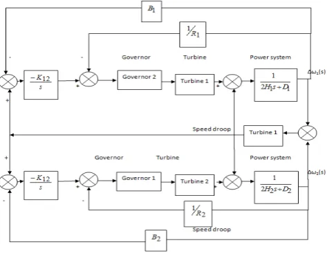
B. AGC in a Multi Area System
In an interconnected (multi area) system, there will be one ALFC loop for each control area (located at the EDC of that area).
Fig. 4: AGC for a multi-area operation
They are combined as shown in Fig.4 for the interconnected system operation. For a total change in load of ∆PRDR, the steady state deviation in frequency in the two areas is given by
2 1 2
1
β
+
β
∆
−
=
∆
=
∆
=
∆
f
w
w
P
D(5)
Where
A
Error! Bookmark not defined.A
(
1
/
)
1 11
=
D
+
R
β
and)
/
1
(
2 22
=
D
+
R
β
.C. Expression for tie-line flow in a two-area interconnected system
Consider a change in load ∆PRD1 Rin area1. The steady state frequency deviation ∆f is the same for both the areas. That is ∆f = ∆fR1R= ∆fR2R. Thus, for areaR1R, we have
∆P
Rm1R- ∆P
RD1R- ∆P
R12R= D
R1R∆f
(6)Where, ∆PR12R is the tie line power flow from areaR1Rto areaR2R and for areaR2R
∆P
Rm2R+ ∆P
R12R= D
R2R∆f
(7)The mechanical power depends on regulation. Hence
1 1
R
f
P
m∆
−
=
∆
And
2 2
R
f
P
m∆
−
=
∆
(8)
Substituting these equations, yields
1 12 1 1
1
DP
P
f
D
R
∆
=
−
∆
−
∆
+
And
12 2 2
1
P
f
D
R
∆
=
∆
+
(9)Solving for ∆f, we get
1 2 1 2 2 1 1 1
)
/
1
(
)
/
1
(
β
+
β
∆
−
=
+
+
+
∆
−
=
∆
DP
DD
R
D
R
P
f
(10) And 2 1 2 112
β
β
β
+
∆
−
=
∆
P
P
D(11)
2 1
2
β
β
+
∆
−
=
∆
f
P
D(12)
And
2 1
1 2 21
12
β
β
β
+
∆
−
=
∆
−
=
∆
P
P
P
D (13)For area 1: ACER1R =
∆
PR12R+ βR1R∆
f (14)For area 2: ACER2R =
∆
PR21R+ βR2R∆
f (15)IV.
Need of Intelligent Control Techniques
Intelligent control techniques are of great help in implementation of AGC for power systems. Some of these techniques are rule based logic programming; model based reasoning, computational approaches like fuzzy sets, artificial neural networks, evolutionary programming and genetic algorithms. In this work, the Particle swarm optimization controllertechnique has been used for AGC of
interconnected power systems
.
A.
Tuning of PI using
Genetic Algorithmstechnique
Genetic Algorithm is an extensive application widely used to solving globally optimized searching problems. The closed form optimization technique cannot be applied to some optimization problems then a genetic algorithm is a better option. Genetic Algorithm find out too many points in the given space for single parameter hence it is more closely to converge towards global minimum solution.
Genetic Algorithm is used to find out optimal parameters of PI controller. Genetic Algorithm is powerful searching method based on the mechanics belongs to natural selection and natural genetics.
Fig.5: Flow chart of Genetic algorithm.
Genetic algorithm based on a population of strings, searching many parallel peaks, opposition to a single point.
• Genetic Algorithm used strings of characters which defining set of parameter.
• Genetic Algorithm follows probabilistic transition rules rather than deterministic rules.
•Genetic Algorithm directly utilized objective function information & not required derivatives or other auxiliary knowledge.
GA method is applied to find out the optimal settings of controller. Genetic algorithm optimization technique is used to minimize performance index which is integral error (AIE) type. Speed deviation has been chosen as an error function. Objective function given is
V.
15TSIMULATION AND RESULTS OF AGC
TECHNIQUE
A. Thermal-Thermal system with and without Tie line, and GA Technique
The area1 and area2 interconnected by tie line bias. Frequency deviation of area1, area2 and deviation tie line bias achieve by MATLAB implementation. We use PI controller and connected to multiport switch and analysis without tie line bias control, with tie line bias control, GA tuned method used
Fig. 6MATLAB Diagram of Two Area (Thermal-Thermal System ) Load Frequency Control
Case-1 Comparison analysis of Deviation in frequency, tie line, for area1, area2 without tie line, with tie line and tie line bias control tuned by GA for a step load of 1% at area1
Fig. 6 to 8 shows the change in frequency deviation ∆𝑓1, ∆𝑓2 and deviation in tie line 𝑃𝑡𝑖𝑒for area1 and area2 a step load of 1% at area1 for without tie line, with tie line,tie line bias control tuned by GA. Analysis and calculates the different parameters maximum deviation, settling time, rise time. The PI tuned GA show better result than tie line bias control.
Fig.6: Change in frequency in area1 without, with tie line bias control and with tie line bias control tuned by GA for a
step load of 1% at area1
Fig.7: Change in frequency in area2 without, with tie line bias control and with tie line bias control tuned by GA for a
step load of 1% at area1
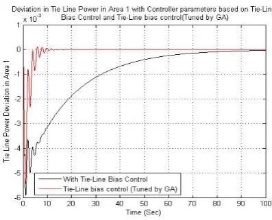
Fig.8: Deviation in tie line without, with tie line bias control and with tie line bias control tuned by GA for a step load of
Case-2 Comparison analysis of Deviation in frequency, tie line, for area1, area2 without tie line, with tie line and tie line bias control tuned by GA for a step load of 1% at area2
Fig. 9 to 11 shows the change in frequency deviation ∆𝑓1, ∆𝑓2 and deviation in tie line 𝑃𝑡𝑖𝑒for area1 and area2 a step load of 1% at area1 for without tie line, with tie line,tie line bias control tuned by GA. Analysis and calculates the different parameters maximum deviation, settling time, rise time. The PI tuned GA show better result than tie line bias control.
Fig.9: Change in frequency in area1 without, with tie line bias control and with tie line bias control tuned by GA for a
step load of 1% at area2
Fig.10: Change in frequency in area2 without, with tie line bias control and with tie line bias control tuned by GA for a
step load of 1% at area2
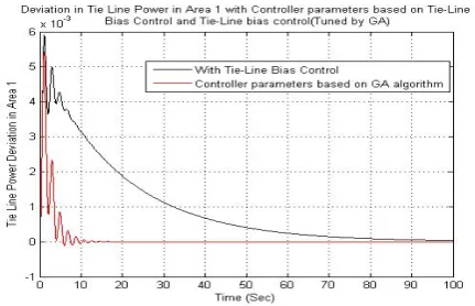
Fig.11
Deviation in tie line without with tie line bias control and with tie line bias control tuned by GA for a step load of1% at area2
B. Comparison Table and discussion for with tie line and for tie line bias control tuned by GA for a step load of 1% at area1 and area2
Table-1
Table6.2 System performance for without tie
line, with tie line and PI tuned GA controller for 1%load
at area1
Table-2
System performance for without tie line, with tie
line and PI tuned GA controller for 1%load at area2
Controller Change in frequency in area1
Change in frequency in area2
Change in tie line power
Setting time (sec.)
Max. deviation (p.u)
Settin g time (sec.)
Max. deviation (p.u)
Setting time (sec.)
Max. deviation (p.u)
Tie line bias control
60.524
7 0.0232 66.7109 0.0168 69.7499 .0059
GA PI 8.4213 .0225 9.418
VI CONCLUSION
Load frequency controller comparison with and without tie line bias controller, GA technique defined. As the effect of tunable parameters of GA technique present in both the areas of the two area system is better. In thermal-thermal system stability can be comes faster The optimal scaling and membership function width parameter are used in system observation give better dynamic results in case load change occurred in both areas in the system. The peak deviation and amplitude of oscillation increases and settling time almost constant. The parameter of controller is managed by GA is give more efficient output. It gives less distortion in output frequency and gives more output power in fewer time limits. Less time to settle the excursions of system state variables within acceptable limits. The system response rise time, maximum deviation and settling time of improve when prefer PI tuned GA technique.
VII REFERENCES
[1]
G. Konar, K. K. Mandal, and N. Chakraborty, “Two AreaLoad Frequency Control Using GA Tuned PID Controller in
Deregulated Environment”, Proceedings of the International
Multi Conference of Engineers and Computer Scientists, vol.2,
12 March 2014.
[2]
Dr. S.K.Bhagat, Binod Rai and Amresh Kumar, “GA basedInternal Model Controller Design for Load Frequency Control
in Power System via Reduced Order Model”, International
Journal of Engineering Science Invention
,vol.3,issue-3,pp.17-26, March 2014.
[3]
El yakine kouba,Nour , “Optimal load frequency controlbased on hybrid bacterial foraging and particle swarm
optimization,”IEEE Multi-Conference on Systems, Signals &
Devices (SSD), 11thInternational,pp.1-6,11-14February 2014.
[4]
K.P. Singh Parmar, “Load Frequency Control ofMulti-Source Power System with Redox Flow Batteries: An
Analysis,” International Journal of Computer Applications,
vol.88, issue-8, pp.46-52, February 2014.
[5]
S. M. Kamali, Dr. Wahida Banu, “A Detailed Analysis ofAutomatic Generation Control In Power Systems,”
International Journal of Emerging Trends in Engineering and
Development, vol.6, issue 3,pp. 482-487, November 2013.
[6]
M. Omar, M. Soliman, A. M. Abdel Ghany, and F. Bendary,“Optimal Tuning of PID Controllers for Hydrothermal Load
Frequency Control Using Ant Colony Optimization”,
International Journal on Electrical Engineering and
Informatics ,vol. 5, issue- 3, pp.348-360 ,September 2013.
[7]
Poonam Rani, Mr. Ramavtar Jaswal, “Automatic loadfrequency control of multi-area power system using ANN
controller and Genetic algorithm”, International Journal of
Engineering Trends and Technology, vol.4, Issue 9,
pp.3777-3783, September 2013.
[8]
Azadani,H.N.,“ Design of GA optimized fuzzy logic-basedPID controller for the two area non-reheat thermal power
system”, IEEE Fuzzy Systems (IFSC), 13th Iranian
Conference on,pp.1-6, 27-29 Aug. 2013.
[9]
Seyed Abbas Taher, Masoud Hajiakbari Fini, and SaberFalahati Aliabadi, “Fractional order PID controller design for
LFC in electric power systems using imperialist competitive
algorithm,” Ain Shams Engineering Journal, vol.-5, pp.121–
135, 2014.
Controller Change in frequency in area1
Change in frequency in area2
Change in tie line power
Setting time (sec.)
Max. deviation (p.u)
Setting time (sec.)
Max. deviation (p.u)
Setting time (sec.)
Max. deviation (p.u)
Tie line bias control
66.7109 0.0168 60.5247 0.0232 6.7499 0.0059