o
o
CENTRAL
PROCESSOR
This manual is published by the UNIVAC. Division in loose leaf format as a rapid and complete means of keeping recipients apprised of UNIVAC Systems developments. The UNIVAC Division will issue updating packages, utilizing primarily a page-for-page or unit replacement technique. Such issuance will provide notification of hardware and/or software changes and refinements. The UNIVAC Division reserves the right to make such additions, corrections, and/or deletions as, in the judgment of the UNIVAC Division, are required by the development of its respective Systems .
• REGISTERED TRADEMARK OF THE SPERRY RAND CORPORATION
UP-3912
Rev. 1
C
C
CENTRAL PRDCESSDR
CONTENTS
1. INTRODUCTION 1.1. SCOPE
1.2. GENERAL DESCRIPTION 1.2.1. Control Function
1.2.2. Arithmetic Function 1.2.3. Storage Function
1.3.
INFORMATION REPRESENTATION 1.3.1. Type of Notation1.4. DATA AND INSTRUCTION FORMATS 1.4.1. General Description
1.4.2. General Instruction Form at
1.5.
STORAGE 1.5.1. General 1.5.2. Tetrads1.5.3. Fixed Interrupt Locations 1.5.4. Addressing
2. CODING IN ASSEMBLY LANGUAGE 2.1. CODING FORM
2.1.1. Program I D 2.1.2. Sequence 2.1.3. Label 2.1.4. Operation 2.1.5. Operands 2.1.6. Comments
2.2. SYMBOLS AND CONVENTIONS 2.3. DATA GENERATION
2.4. PAL JR ASSEMBLY SYSTEM
Contents 1
SECTION. PAGE.
CONTENTS
1 to 3 1-1 to 1-13
1-1 1-1 1-1 1-1 1-1 1-1 1-1 1-9 1-9 1-9 1-10 1-10 1-11 1-12 1-13 2-1 to 2-11
UP-3912
Rev. 1
UNIVAC 1050 SYSTEMS
CENTRAL PRDCESSDR
3. INSTRUCTION REPERTOIRE
3.1. TETRAD INSTRUCTIONS 3.1.1. Bring to Tetrad
3.1.2. Sto re T etr ad 3.1.3. Add to Tetrad 3.1.4. Compare Tetrad 3.1.5. Fix Tetrad
3.2. DATA TRANSFER INSTRUCTIONS 3.2.1. Bring Decimal
3.2.2. Bring Alphanumeric 3.2.3. Store Arithmetic Register 3.2.4. Store Both Arithmetic Registers 3.2.5. Store Character
3.2.6. Transfer Block from Store 3.2.7. Transfer Block to Store 3.3. ARITHMETIC INSTRUCTIONS 3.3.1. Add Decimal
3.3.2. Subtract Decimal 3.3.3. Add to Memory 3.3.4. Subtract from Memory 3.3.5. Multiply Noncumulative 3.3.6. Multiply Cumulative 3.3.7. Divide
3.3.8. Add Binary 3.3.9. Subtract Binary 3.3.10. Add Ch aracter
3.4. COMPARISON INSTRUCTIONS 3.4.1. Compare Decimal
3.4.2. Compare Binary 3.4.3. Compare Character 3.4.4. Logi cal Compare
3.5. SEQUENCE CONTROL INSTRUCTIONS 3.5.1. Jump
3.5.2. Jump if Greater 3.5.3. Jump if Equal 3.5.4. Jump if Unequal 3.5.5. Jump if Smaller 3.5.6. Halt then Jump 3.5.7. Jump Display 3.5.8. Jump Conditional 3.5.9. Jump Return 3.5.10. Jump Loop
3.6. EDITING INSTRUCTIONS 3.6.1. Transl ate
3.6.2. Edit
3.6.3. Zero Suppress 3.6.4. Pad Blanks 3.6.5. Pad Zeros 3.6.6. Logical Sum 3.6.7. Logical Product 3.6.8. Bit Shift 3.6.9. Bit Circulate
Contents 2
SECTION: PAGE:
3-1 to 3-73 /~
"-='
3-6 3-7 3-7 3-8 3-9 3-10 3-12 3-14 3-16 3-17 3-17 3-18 3-20 3-22 3-24 3-26 3-28 3-29 3-31 3-32 3-34 3-36 3-383-39 /~
3-40 ,,~
3-42 3-44 3-46 3-47 3-48 3-50 3-51 3-51 3-51 3-51 3-51 3-53 3-53 3-54 3-56 3-59 3-60 3-61 3-63 3-66 3-68 3-68
3-69 '1' l~ ,
3-70
\..J
3-71
3-72 I
Rev. 1
c
c
C
CENTRAL PRDCESSDR
4. AUTOMATIC PROGRAM INTERRUPT
4.1. 4.2.
4.2.1.
4.2.2. 4.2.3. 4.2.4.GENERAL DESCRIPTION
PROGRAMMING CONSIDERATIONS Classes of Interrupt
Programmed Interrupt Inhibit
Instructions Associated with Interrupt Control Fixed Interrupt Locations
5. CENTRAL PROCESSOR CONSOLE OPERATION
5.1. NORMAL OPERATION 5.1.1. Start Up and Shut Down 5.1.2. Program Start and Program Stop 5.1.3. Operating Mode
5.2. PANEL CONTROLS AND INDICATORS
5.3. 5.3.1. 5.3.2. 5.3.3. APPENDIX
A.
PROGRAM DEBUGGING AND TESTING Use of Display Lights and Switches Error Indicators
Sense Switches and Operator Request
Octal - Decimal Conversion Table
SECTION:
4-1 to 4-5
4-1 4-1 4-1 4-3 4-3 4-3
5-1 to 5-12
5-1 5-1 5-1 5-1 5-2 5-7 5-7 5-10 5-11
1 to 4
PAGE:
TABLES AND FIGURES
TABLES
1-1 UNIVAC 1050 Character Set 1-6
1-2 Tetrad Location Chart 1-11
3-1 Suggested Standard Equal ity Statements 3-2
3-2 Instruction Repertoi re 3-3
3-3a Mnemonic Operations, Ordered by Operation Code 3-5
3-3b Mnemonic Operations, Ordered Alphabetically 3-5
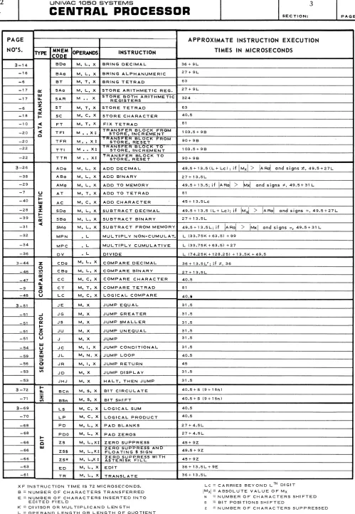
3-4 Instruction Execution Times 3-73
4-1 Indicator List 4-4
5-1 Control Console Switch and Indicator Descriptions 5-2
FIGURES
1-1 Layout of The First Six Rows of Store 1-10
2-1 PAL Assembler Coding Form 2-2
2-2 PAL SO-Column Source Card 2-3
2-3 PAL 90-Column Source Card 2-3
3-1 Layout of Fi rst Si x Rows of Store 3-4
5-1 Central Processor Console 5-12
I'
, iUP-3912
Rev. 1
CENTRAL PRDCESSDR
SECTION. PAGE.c
1. INTRODUCTION
1.1. SCOPE
The primary purpose of this manual is to provide the basic knowledge necessary for programming the UNIVAC 1050 Central Processor, and serve as a reference for the programmer. Background information is provided on the internal operation of the Central Processor and the different types of information representation, as well as information on data and instruction formats, specialized areas of storage (registers, I/O control tetrads, etc.), coding, the instruction repertoire, and automatic program interrupt.
A second purpose of this manual is to describe the Central Processor Console and its operation, and serve as a reference for the operator. A detailed description of all the console controls and indicators is provided along with a description of their use to communicate with the program and control various normal and abnormal conditions.
1.2. GENERAL DESCRIPTION
The Central Processor is the control center of the UNIVAC 1050 System. It contains the circuitry for logic and arithmetic operations, the core storage and the power supply.
The Central Processor performs three main functions: • Control
• Storage
• Arithmetic Computation 1.2.1. Control Function
The control circuitry of the Central Processor accesses and executes instructions from storage. It also maintains control over the operation of all peripheral devices. External control is
facilitated by the lights and buttons on the Central Processor Console. 1.2.2. Arithmetic Function
The arithmetic function instructions employ the arithmetic registers to perform binary and deci-mal addition and subtraction, as well as decideci-mal multiplication and division. Overflow is indi-cated and decimal sign control is provided.
1.2.3. Storage Function
The storage function of the UNIVAC 1050 Central Processor is provided by one to eight modules of core storage, each containing 4096 characters.
1.3. INFORMATION REPRESENTATION* 1.3.1. Type of Notation
Digital computers employ a system of notation called the binary system. Unlike the decimal
system which uses ten symbols (0 through 9) and is based on a radix (root) of 10, the binary system employs only two symbols (0 and 1) and is based on a radix of 2.
* The reader familiar with numbering systems may wish to skip to Section 1.4. DATA AND INSTRUCTION
UP-3912 Rev.
1
UNIVAC 1060 SYSTEMS
CENTRAL PRDCESSDR
SECTION.1 2
PAGE:
The two symbols of the binary system represent the two possible states of an information convey- / ' " ing electronic device. The 1 symbol indicates a registered pulse while the 0 symbol indicates a
'~'
no pulse registration. Information is represented in the computer by pulse-no-pulse combinationswith a specific pattern for each alphabetic, numeric, and special character.
1.3.1.1. Decimal and Binary
Numbering systems are based on positional notation. That is, each digit in a quantity is weighted with a specific value. The value of a digit is determined by its position within the quantity and the radix of the numbering system. For example, using decimal notation, the number seven thousand four hundred sixty nine would be represented as 7469 which is equi valen t to
Note that each digit, from right to left, is considered to be multiplied by a successively higher power of 10.
The binary system is also based on a system of positional notation, but, as was stated previously, it uses a radix of 2 and employs only two symbols to represent quantities. For example, the number nine expressed in pure binary would be
1001
which is equivalent to
Note that each binary digit (bit), from right to left, is multiplied by successively higher powers of 2.
1.3.1.2. Fixed Length Notation
Instead of specifying information with a variable series of binary digits (the length of the series dependent upon the quantity to be specified) representing successively higher powers of 2, a system of notation is used that specifies information by smaller, fixed length groupings of binary digits. Each grouping, fixed in format as well as length, is used to represent a digit, an alphabetic character, or a special symbol. Assuming a system of notation that employs a fixed length format, a single digit would be represented by a single group of bits, a two digit
polynomial by two bit groupings, a three digit polynomial by three bit-groupings, and so forth. For example, in pure binary the number 27 would be
11011
UP-3912 Rev. 1
c
c
CENTRAL PRDCESSDR
SECTION:However, by employing a fixed format of 4 bit notation, known as binary coded decimal, the number 27 would be represented as
0010 0111
2 7
and similarly, the num ber 369 as
0011 0110 1001
3 6 9
PAGE:
Note that within each 4 bit grouping, the bit positions are weighted with a value of 8, 4, 2, and 1 or 23 , 22, 21, and 2°. The decimal digits 0 through 9 then are represented in the following manner:
DECIMAL BINARY 4 BIT NOTATION
0 0000
0001
2 0010
3 0011
4 0100
5 0101
6 0110
7 0111
8 1000
9 1001
With 4 bit positional notation, only 16 unique permutations can be created. This is obviously insufficient to specify all numeric, alphabetic, and special characters generally employed in a computing system. By adding two more bit positions and using them as a qualifying factor to a 4 bit combination, a total of 64 unique permutations can be represented. The four bit positions on the right are called the numeric portion. Two additional positions on the left, which
represent no actual numeric quantity, are called the zone portion.
Qualification of a numeric quantity is unnecessary, therefore, the zone portion is always 00. When representing alphabetic characters or special symbols, however, a 1 bit is entered in either or both zone positions. The letters A through I, therefore, may be represented with the numeric portion specifying a value from 1 to 9 (0001 to 1001) and the zone portion containing a 01 qualifier; the letters
J
through R with the same numeric specifications but with a zone qualification of 10; and finally, the letters S through Z with a numeric specification of from 2 to 9 and a zone qualification of 11. So, for example, the letters A,J,
and S would berepresented as
ZONE
01 10 11
NUMERIC
0001 0001 0010
CHARACTER
A
J
UP-3912 Rev. 1
UNIVAC 1050 SYSTEMS
CENTRAL PROCESSOR
1
4SECTION. PAGE.
---~---~---~~~----~~---I
This is not the same as UNIVAC 1050 code however.
The zone and numeric specifications for special symbols such as the comma, apostrophe, asterisk, and so forth are dependent upon computer design. That is, computers are wired to accept a unique bit combination for a particular special symbol. Since there is no natural sequence relationship between special symbols, as with numerics or alphabetics, the bit configuration for special symbols must be arbitrary. The sequence for UNIVAC 1050 special symbols is shown in Table 1-1.
1.3.1.3. Excess Three (XS 3)
Excess three (XS 3) is a method of notation that is used by the UNIVAC 1050
System. It establishes some measure of compatibility with the data formats of the other UNIVAC Computing Systems. The zone position is specified in the standard manner previously described for fixed length binary coded decimal notation. The difference exists in the numeric portion where each binary specification is a value that is three greater than its decimal equivalent. For example, the number 8 is represented in XS 3 as
ZONE NUMERIC
00 101 1
Note that the numeric portion, weighted with positional values of 8, 4, 2, and 1 from left to right, is actually equal to 11. Similarly, the number 6 is represented as
ZONE NUMERIC
00 1001
Here the numeric portion is specified as 9 or three greater than the decimal digit it represents.
There are several reasons for utilizing this method of notation in certain UNIVAC Systems; some of these reasons are
• It allows three quantities to test less than. O.
• It facilitates complementation.
• It permits the carry to occur as in decimal notation.
An involved discussion of these and other reasons for the utilization of XS 3 notation is beyond the scope of this manual. It is sufficient that the programmer is aware of the basic format and that this provides in the UNIVAC 1050 Computer a factor of data compatibility with other UNIVAC Systems. Table 1-1 gives a listing of the XS 3 code configurations for all the alphabetic, numeric, and special characters utilized in the UNIVAC 1050 System.
{-",
UP-3912
Rev. 1
CENTRAL PROCESSOR
SECTION. PAC;E:
o
1.3.1.4. Parityo
A parity check is used by the computer to ensure that accurate transmission of data occurs. The parity position is an extra bit position added to ensure that there will always be an odd number of 1 bits in any character representation. In this way, if a bit is either dropped or added in transmission, the odd parity check will indicate an improper registration. For example, the alphabetic S contains an even number of 1 bits:
ZONE NUMERIC
11 0101
To pass the odd parity check, a 1 bit is added to the parity position, thereby creating an odd number of 1 bits in the representation:
PARITY ZONE NUME RIC
11 0101
If the number of 1 bits in the configuration is already odd, the parity position will be O.
1.3.1.5. Octal Numbers and Complements
Octal notation is used in source language and program testi~g diagnostic printouts. The octal or base 8, number system expresses values as multiples of powers of 8.
Octal notation is a fixed length system of binary notation. The binary number is interpreted octaUy by grouping the bits into bytes of three, starting from the right, and interpreting each byte into its octal equivalent. W.ithin each byte the bit positions are weighted with the value of
4,2, and 1, or 22, 2', and 2°. If, after grouping the bits in the fashion described, the most significant byte contains less than three bits, as many binary zeros are implied to the left as are required to bring the number of bits in that group to three. For example, the binllry number
10011101101 is interpreted octally as follows:
(0) 10
2
011
3
101
5
101
5
An octal number such as the one derived from the binary number described is noted with the subscript 8 following it, e.g., 23558 , to distinguish it from the decimal number 2355,0 , In the
UP-3912 Rev. 1
UNIVAC 1050 SYSTEMS
CENTRAL PROCESSOR
HIGH-SPEED PRINTER CARD CODES BINARY CODE CHARACTER
80 90 (Machine Collatin!
COLUMN COLUMN Sequence) STANDARD OPTIONAL OCTAL Space
NO PUNCH NO PUNCH 000000 (Non-Printing) 00
11-5-8 1-3-5-7 000001 ] 01
- (minus or
11 0-3-5-7 000010 hyphen) 02
0 0 000011 0 03
1 1 000100 1 04
2 1-9 000101 2 05
3 3 000110 3 06
4 3-9 000111 4 07
5 5 001000 5 10
6 5-9 001001 6 11
7 7 001010 7 12
8 7-9 001011 8 13
9 9 001100 9 14
0-6-8 0-1-3-7-9 001101
"-
1511-6-8 1-3-5-7-9 001110 ; 16
12-5-8- 0-5-7-9 001111 [ 17
12 0-1-3-5-7 010000 + & 20
5-8 1-3-7-9 010001 : (colon) 21
12-3-8 1-3-5-9 010010 _ (period) 22
12-0 0-1-3 010011 ? 23
12-1 1-5-9 010100 A 24
12-2 1-5 010101 B 25
12-3 0-7 010110 C 26
12-4 0-3-5 010111 D 27
12-5 0-3 011000 E 30
12-6 1-7-9 011001 F 31
12-7 5-7 011010 G 32
12-8 3-7 011011 H 33
12-9 3-5 011100 I 34
3-8 0-1-5-7 011101
-
# 3512-6-8 0-1-5-9 011110 < 36
12-7-8 0-1-3-5-7-9 011111 # =- 37
7-8 0-1-5-7-9 100000 @ • (apostrophe) 40
11-4-8 0-1 100001 * 41
11-3-8 0-1-3-5-9 100010 $ 42
11-0 0-3-7-9 100011 ! 43
11-1 1-3-5 100100 J 44
11-2 3-5-9 100101 K 45
11-3 0-9 100110 L 46
11-4 0-5 100111 M 47
11-5 0-5-9 101000 N 50
11-6 1-3 101001 0 51
11-7 1-3-7 101010 P 52
11-8 3-5-7 101011 Q 53
11-9 1-7 101100 R 54
0-5-8 0-1-9 101101 % ( 55
4-8 0-1-3-7 101110 ' (apostrophe) @ 56
11-7-8 0-1-7 101111 f:,
57 0-2-8 0-1-7-9 110000
*"
600-4-8 0-1-5 110001 ( % 61
0-3-8 0-3-5-9 110010 ,(comma) 62
2-8 1-5-7-9 110011 & + 63
0-1 3-5-7-9 110100 J 64
0-2 1-5-7 110101 S 65
0-3 3-7-9 110110 T 66
0-4 0-5-7 110111 U 67
0-5 0-3-9 111000 V 70
0-6 0-3-7 111001 W 71
0-7 0-7-9 111010 X 72
0-8 1-3-9 111011 y 73
0-9 5-7-9 111100 Z 74
12-4-8 0-1-3-9 111101 ) ):l 75
6-8 0-3-5-7-9 111110
>
760-7-8 0-1-3-5 111111 ):l ) 77
*NOTE: Only the characters that differ from the standard are listed for the optional print drum.
Table 1.1. UNIVAC 1050 Character Set.
. . .
1 6
SECTION: PAGE:
UP-3912
Rev. 1
c.···
. ,. j
o
CENTRAL PRDCESSDR
SECTION.The binary number 10011101101 is the sum of
1 x 2'0 1024
o
x 29 00 x 28 0
x 27 128
x 26 64
x 25 32
0 x 24 0
x 23 8
x 22 4
0 x 2' 0
x 20
1261
Therefore, 23558 = 1261, o.
Appendix A provides a two-way octal to decimal and decimal to octal conversion table. For the convenience of the programmer who wishes to do his own conversions, the following paragraphs present an octal to decimal and a decimal to octal conversion procedure.
To convert an octal representation to its decimal equivalent, multiply the most significant digit by 8, and add the next most significant digit to the product. Multiply this sum by 8 and add the third most significant digit to the product. Repeat the multiplication and addition process until the least significant digit has been added, whereupon this final sum will be the decimal equivalent of the octal number.
The following example illustrates how this method converts 23558 into its decimal equivalent: 2x8=16
+ 3
19x8=152
+ 5
157x8=1256
+ 5
1261
UP-3912 Rev. 1
UNIVAC 10150 SYSTEMS 1
CENTRAL PRDCESSDR
SECTION: PAGE:The following example illustrates how this method converts 1261'0 into its octal equivalent:
REMAINDER
0 .. 2
B~ .. 3
B~ .. 5
Brt3f. .. 5 B) 1261
No signs are involved in binary operations in the UNIVAC 1050 System; however, negative binary values - or, effectively, their equivalent - can be developed and represented within the computer. These negative binary values are represented as the two's complement of the binary representation of the absolute value of the numbers. The two's complement is formed by adding 1 to the one's complement of the value, ignoring any carry beyond the most significant bit position; and the one's complement, in turn, is formed by converting every 1 bit in the binary representation to 0, and converting every 0 bit to 1.
For example, the binary representation of +1261'0 is 010011101101 the one's complement of this binary number is
101100010010 and the two's complement of the number is
101100010010
+ 1
101100010011
=
54238Whenever the binary integer 101100010011 is employed as an operand in a binary add or subtract operation, the effective value of this operand is -1261,0'
8
,,<' ""'\
\~~)
UP-3912
Rev. 1
CENTRAL PRDCESSDR
SECTION, PAGE.
c
1.4. DATA AND INSTRUCTION FORMATS 1.4.1. General DescriptionInstructions are contained in storage. They are always five characters in length whereas data fie~ds may be any number of characters in length. Instructions are executed in sequence except where a programmed instruction initiates a break in the sequence.
The arithmetic unit of the Central Processor performs the calculations and data man-ipulation called for by the instructions. It contains an adder for decimal and binary arithmetic operations, and additional circuitry which provides a wide range of data handling abilities.
The control unit of the Central Processor selects, interprets, and initiates the exe-cution of instructions in the stored programs which govern the operation of the system.
1.4.2. General Instruction Format
1st CHARACTER
I
2nd CHARACTERl
3rd CHARACTERI
4th CHARACTER 5th CHARACTERI
I
i
IOPERATION It:l DEX vi I I
DETAIL
w STORAGE ADDRESS
CODE REGISTER It: I I
OBITS
I I I30 26 2S I 23 22 21
i
I 7 6 1BIT POSITIONS
30 - 26
25 - 23
22
21 - 7
6 - 1
c:'
NAME
OP ERATION CODE
INDEX REGISTER
RESERVED
STORAGE ADDRESS
DETAIL FIELD
The operation code specifies the function which the Central Processor is to execute.
The index register modifies the oddress specified
in the instruction.
This bit is reserved.
This is the (M) portion of the instruction. It
specifies the store address of the operand. If an operand is greater than one character in length, (M)
refers to the least significant character of the operand (rightmost). There are two exceptions: Zero Suppress and Block Transfer instructions in which (M) specifies the most significant character of the operand.
Depending on the instruction, the detail field may
--~---- ---~---
.--.---~---llP-3912 Rev. 1
UNIVAC 1050 SYSTEMS
CENTRAL PROCESSOR
1
SECTION: PAGE:
1.5. STORAGE 1.5.1. General
The basic unit of storage in the UNIVAC 1050 store is the character which consists of six information bits and one parity bit. The parity bit is of no concern to the programmer. It is used only by the circuitry and is not accessible to him.
The UNIVAC 1050 Central Processor may have from 1 to 8 sections of storage, each section comprisi ng 4096 character positions or locations. Each position has its own address and each position is directly addressable.
Each section of main store is divided into rows. There are 64 rows in each section. A row consists of 64 consecutive characters. The address of the most significant character (leftmost) is either zero or some integral multiple of 64.
Program instructions and data are contained in storage. Each instruction occupies five con-secutive locations. Data fields are variable in length. The sign, if any, of a data field is in the most significant bit of the least significant character.
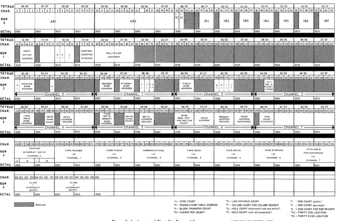
The first six rows of storage, portions of which perform unique functions, are illustrated in Figure 1-1.
ROW o
CHAR.
ROW
,
CHAR.
ROW
2
CHAR. ROW
J
CHAR. ROW
,
_ R e s e r v e d " ZERDCDUNT
'e L~EADVANCECOUNT 'r ROI'I COUNT Ipul1r.l> 'b TRA.NSLATION TABLE ADDRESS 'f COLUMN COUNT FOR COLUMN READER 'I RDIVCQUNTIpr""readl'
*c BLDCKTRA.NSFERCOUNT
~d' CfoIARACTER COUNTI
'g HOlF COU'H ,post-punch read ao~ punchl' 'k "ROW COUNT FOR ROW READER
'h HOLE COUNT 'wait and p,e·punchl , '1(2 PARITYODQLDCATIQrI 'Kl PARITY EVEN LOCATION
,USED ONLY BY CONTROL UNITS
Figure 1-1. Layout of First Six Rows of Store.
UP-3912
Rev. 1
CENTRAL PROCESSOR
SECTION:PAGE:
c
1.5.2. Tetradso
The first four rows of storage in the UNIVAC 1050 System are subdivided into 64 fields of four characters each and are called tetrads. Tetrads are addressable either by tetrad number or the actual storage location. The method of addressing tetrads is dependent upon the instruction being used. Certain tetrads are designed for specific functions. A description of what these tetrads do is given in the following table.
TETRADS LOCATIONS PURPOSE
0-3 0-15 *Arithmetic Register 1 (ARl) 4-7 16-31 *Arithmetic Register 2 (AR2) 8 32,33 Character bit sum storage. 9-15 36-63 *Index Registers 1-7
16 64-67 Destination address for Block Transfer 17 68-71 Origin address for Block Transfer 18 72 Address of table for trans lation
18 73 Count of zeros suppressed after Zero Suppress. 18 74,75 Controls number of characters in Block Transfer 19 77-79 Control Counter Storage
20-21 80-87 Multiplier - Quotient 22-31 88-127 Unassigned
32-35 128-143 Printer I/O, Channel 0 36-39 144-159 Reader I/O, Channell 40-43 160-175 Punch I/O, Channel 2
44-47 176-191 Communications I/O, Channel.3 48-51 192-207 Tape Read, Channe I 4
52-55 208-223 Tape Write, Channel 5 56-59 224-239 FASTRAND I/O, Channel 6 60-63 240-255 Channel 7, available for expansion
* The arithmetic registers and index reQisters can be addressed in three different ways: as arithmetic or index
re,isters, 8S tetrads, and as store locations.
Table 1-2. Tetrad Location Chart
1.5.2.1. Arithmetic Registers
UP-3912 Rev. 1
UNIVAC 1060 SYSTEMS
CENTRAL PROCESSOR
1
SECTION: PAGEl
1.5.2.2. Index Registers
Tetrads 9 through 15 function as index registers 1 through 7. Since only tRe 15 least signifi-cant bits (contained in the three least signifisignifi-cant characters) of each index register are used in an indexed operation, the most significant character of each index register tetrad is avail-able to be used for other purposes.
There are no signs in the index registers. The value in the index register is treated as an absolute binary value in an indexed operation. Negative indexing may be accomplished by placing the two's complement of the decrement number in the index register.
The index registers may be addressed by index register number, tetrad number, or actual storage location number.
1.5.2.3. Input/Output Control Tetrads
1.5.3.
A fixed storage area consisting of four consecutive tetrads is associated with each input/out-put channel. Information placed in this area controls the operation of the peripheral device. The input/output control tetrads, that are located in storage rows two and three, are shown in Figure 1-1.
Fixed Interrupt Locations
Store locations 256 through 335 are fixed locations associated with the interrupt circuitry of the system. These eighty locations are divided into ten groups of eight consecutive characters each, which are known as interrupt entries. These interrupt entries are assigned as follows:
OCTAL DECIMAL INTERRUPT ENTRY ASSIGNMENTS
0400 - 0407 256 - 263 Channel 0: Printer
0410 - 0417 264 - 271 Channel 1 : Reader
0420 - 0427 272 - 279 Channel 2 : Card Punch Unit
0430 - 0437 280 - 287 Channel 3 : Communications
0440 - 0447 288 - 295 Channel 4: Magnetic Tape Read
0450 - 0457 296 - 303 Channel 5: Magnetic Tape Write
0460 - 0467 304 - 311 Channel 6 : Mass Storage
0470 - 0477 312- 319 Channel 7 : Unassigned
0500 - 0507 320 - 327 Class I Interrupt Entry
0510 - 0517 328 - 335 Class II Interrupt Entry
The format of these interrupt entries, and their functions, are discussed fully in the section on Automatic Program Interrupt (Section 4).
12
UP-3912
Rev. 1
CENTRAL PRDCESSDR
SECTION: ""caE:
C
1.5.4. AddressingC·.·"'
.".Instructions and data in storage are accessed by other instructions through the 15 bit memory address designated the M portion of the instruction.
UP-3912 Rev. 1
o
CENTRAL PROCESSOR
SECTION: PAGE:2.
CODING IN ASSEMBLY LANGUAGE
2.1. CODING FORM
c)
Most programs for a UNIVAC 1050 System with 8192 character storage or larger are written in the language of the PAL Assembly System. Programs for a system with 4096 character storage are written in PAL Jr. See Section 2.4. The PAL assembler is a UNIVAC 1050 program which accepts mnemonic and symbolic input, a form meaningful to the programmer, and generates in-structions in absolute binary form, the only form meaningful to the computer. Any action based on attempts to employ instruction forms not described in this reference manual deviates from UNIVAC recommendations and must be the user's responsibility.
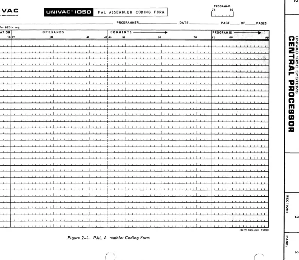
Figure 2-1 shows the symbolic coding form for the UNIVAC 1050 Pal Assembly System.
In the description of this form, which follows, certain terms are used with specific definitions:
•
Alphabetic•
Numeric•
Alphanumericcharacter means a character of the English alphabet set (A through Z). character means a character of the Arabic numeral set (0 through 9). character means an alphabetic character, a numeric character, or a special symbol.
The symbolic coding format is composed of fixed format fields for program identification, page, line, insert, label, operation, and variable format fields for operands and comments.
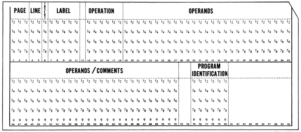
It will be noted that numbers are associated with each subdivision of the coding form. These indi-cate the card columns into which the characters written by the programmer are to be punched. These column numbers hold true for both 80 and 90 column cards. The 80 column source card is shown in Figure 2-2; the 90 column source card, in Figure 2-3 In 90 column systems, columns 81 through 90 are also available to the Program-ID field, but their contents will not be printed on the output listing; their use, therefore, is not recommended.
2.1.1. Program-ID
The program name is written in this field. It is composed of from one to six alphanumeric characters, and is written starting at column 75. An example of an entry in this field is
PROGRAM-ID
75
80
PAGE PROGRAM·ID
U
75 80I
I II
UNIVAC
"'%"""'-"'1-'
PAL ASSEMBLER CODING FORM
PROGRAM ______________________________________________________________ __ PROGRAMMER ______________ ___ DATE PAGE ___ OF _ _ PAGES
For BEGIN onl
SEQUENCE LABEL ~ OPERATION OPERANDS I COMMENTS ~ PROGRAM.ID .. !
{ AGE3
kiN! ;;
7 11 13 18 19 30 40 45,
146 50 60 70 75 80 < 9G II
I I
/',
'i'
I
,
II I
;
I I I " , .' ,,' .I I I I I I '~"'\!¢"
I I
;
I I I.,'; I;'.
I I , I I I
.'
>,
I I
:
I I I ,"~II I
:
I I I , . iI I
;
I I J,
I I I I I
I I I I I I
I .L I J I I
I I I I I I
I I I I I I
I I
,
I I II I I I I I
I I I I I I
I I I I I I
I I 1 I I I
I I I I I I I
I
I I I I I
I I I I I I
I I I I I I ,
I I I I I I
I I I I I I
.L I I I I I
I I I I I I
I I
,
I I II I I I I I
I I
,
I I I,-, ,-, I I I I I I I I I I I I I I I I t I I I I I I I I I I I I L I I I I I : I I I I I I I I I I I I I I I I I I I I I I I I I I I I I I I I I I I 1,1 I I 1 I I I
UD1·802 13/1256 125M 7/65 (80·90 COLUMN FORM)
Figure 2-1. PAL A. -embler Coding Form
-'"
::tiC:::
Cb "0
< '
Rev. 1
o
(
.~/
CENTRAL PRDCESSDR
PECT'ON. PAGE.I
PAGE
LINEI
LABEL OPER.
OPERANDS
PROGRA
R
:
COMMENTS
IDENT.
T
000 00 000000 0000000 ooooooooooooooooooooooooooo~oooooooooooooooooooooooooo 0 0 000000
, 2 3 4 I
I , . " ' " , '3 14 15 111111 11202'22 22 24 25 2121212130 3111 33 34 35.31 • • 4114142 43 44.:. 41 • • 115152 53 54l1li11151111111011121314 II II 611111111 II n 1114 7111 n Ill . . '
1 1 1 11 111111 1111111 1 1 1 1 1 1 1 1 1 1 1 1 1 1 1 1 1 1 1 1 1 1 1 1 1 1 1:1 1 1 1 1 1 1 1 1 1 1 1 1 1 1 1 1 1 1 1 1 1 1 1 1 1 1 11 111111
I
222 22 222222 2222222 222222222222222222222222222:222222222222222222222222 2 2 2 22 222222
I
333 33 333333 3333333 3 3 3 3 3 3 3 3 3 3 3 3 3 3 3 3 3 3 3 3 3 333 3 3 313 3 3 3 3 3 3 3 3 3 3 3 3 3 3 3 3 3 3 3 3 3 3 3 3 3 3 33 333333 444 44 444444 4444444 44444444444444444444 44 4 44 4 4:4 44 4 4 4 44 44 4 4 4 44 4 4444 4 4 4 444 4 I 44 444444 555 55 555555 5555555 5 5 5 5 5 5 5 5 5 5 5 5 5 5 5 5 5 5 5 5 5 555 5 5 5:5 5 5 55 5 5 5 5 5 5 5 5 5 5 5 5 5 5 5 5 5 5 5 5 5 5 55 555555
I
86& && &&&&86 1868686 6 6 6 6 6 6 6 6 6 & 6 & & & & & & & & & & & & 6 & & 6:6 & 6 & & & & & & 6 6 & 1 6 6 6 1 6 6 6 6 6 6 6 6 6 6 66 866666
I
711 71 717171 1777777 11111111111111 7 11 7 1 7 7 111 7 7 111111 7 7 111 7 7 11111111 7 111111 7 71 177771
I
888 88 888888 8888888 888888888888888888888888888:888888888888888888888888 8 8 8 88 888888
I
999 99 999999 9999999 999999999999999999999999999:999999999999999999999999 999 99 999999
t 2 S 4 5 ,'8,1111 12111411111111 1120~222224252121D2520~II333425.31 • • 4II~424344.~61 • • 30~525354I111I1151I1I1.I15ZI3I4.I161UIl1llIln 1114 1518 n 1111. I
Figure 2-2. PAL 80-Column Source Cord.
,
"
PAGE LINE I
ELABEL
OPERATION
OPERANDS
1\
R
,
ii-
1z-12-
Ii-Iii2
1i-G-1z-i"2--
ii
-- ii-1z-G-I2"-i"z--'z Iz-lzlz-1;-'z-li-'z-lz-i"2Iz-i"i-'z-li-G-I2"-';-'z-'i-'z-li-'z-lz-'212"-';-'z-lz
3. 3. 3. 3. 3. 34 3<1 3. 3. 3. 3. 3. ~. 3. 3. 3. 3. 3. 3. 34 3. 3. 3. 3. 3. 3. 3. 3. 3. 3. 3. 3. 3. 3. 3. 3. 3. 3. 3. 3+ 3. 3+ 3. 3.
56 56 56 56 56 56 56 56 56 56 56 56 56 56 56 56 56 56 56 56 56 56 56 56 56 56 56 56 56 56 56 56 56 56 56 56 56 56 56 56 56 56 56 56
78 78 78 78 78 78 78 78 78 78 78 78 78 78 78 78 78 78 78 78 78 78 78 78 78 78 78 78 78 78 78 78 78 78 78 78 78 78 78 78 78 78 78 78
1
,
3•
•
•
7 8•
10 11 12 13 14 IS 1. 17 18" 20 21
"
23,.
os,.
21" 28,.
30 31 32"
3. 35 3. 37 38 3. 40 41.,
43..
••
OPERANDS / COMMENTS
IDENTIFICA nON
PROGRAM
--- ---
12-';-'Z-'2-'21
2
---'2
'2 12 12 12 12 12 12 12 12 12 12 12 12 12 12 12 12 12 12'2
12 '2 12 12 12 1234 34 3+ 3. 3+ 3. 3. 34 3. 3. 3. 3. 3. 3. 3. 3. 3. 3. 3. 3. 3. 3. 3. 3. 3. 3. 3. 34 3. 34 3. 3. 3.
56 56 56 56 56 56 56 56 56 56 56 56 56 56 56 56 56 56 56 56 56 56 56 56 56 56 56 56 56 56 56 56 56
78 78 78 78 78 78 78 78 78 78 78 78 78 78 78 78 78 78 78 78 78 78 78 78 78 78 78 78 78 78 78 78 78
9 9 9 9 9 9 9 9 9 9 9 9 9 9 9 9 9 9 9 9 9 9 9 9 9 9 9 9 9 9 9 9 9
••
.7.. ..
'0 51 52 53 54,.
56 .7 58••
60.,
62 53 54••
..
'7.. ..
70 71 72 73 74 75 7. 77 78 7. 80 81 8' 83 8. 8' 8. 87 88 8' '0Figure 2-3 •• PAL 90-Column Source Cord.
2.1.2. Sequence
This field is a six character numeric field composed of a three digit page field, a two digit line field, and a one digit insert field. There may be a page field entry and a line field entry on each card.
UP-3912 Rev. 1
UNIVAC 1050 SYSTEMS 2
CENTRAL PRDCESSDR
SECTION. PAGE.The insert field is provided to permit the insertion of additional coding lines when correct-ing a source program. The insert field entry consists of one numeric digit. This field is used when a line of coding is to be inserted on a particular page following a particular line. To insert a line of coding between lines 23 and 24 of page 10, the coding used could be
SEQUENCE
\
,PAGE
3
LlN,l=4 5
6 ':IS7
0,1
o
2 3
7I I
There is one restriction on the digit used for INS. If more than one instruction is to follow a particular page and line, each insertion line must have a sequentially higher INS number than any preceding it.
If inserts are made, the cards punched from the insert lines must be physically placed in their proper places in the source deck, prior to assembly.
2.1.3. Label
A label is an alphanumeric symbol associated with the line on which it appears. It consists of five characters or less, the first character of which must be an alphabetic character other than the letter X. A label must begin in column 7,and is terminated either by column 12 or by the first blank appearing in the field. The entire field may be blank. (Column 12 can be used only by a six character label, if any, of the assembler directive BEGIN or by a comments line. Otherwise it is always left blank.)
The label of an instruction line names the leftmost character of the instruction, while the label of a data field or a constant names the rightmost character of the field or constant. Some examples of labels are
"
...
E
LABEL
0
~T
j7
1113
S T A R T ",;
I
G 1 2
1"1':,EN
DR N ~1,~ )I :,'.:
-
-4
, ( - ,
\~j
UP-3912 Rev. 1
c
()
,
t
UNIVAC 10150 SYSTEMS 2
CENTRAL PROCESSOR
SECTION, PAGE,If column 7 contains a period, the entire line is a comment. It produces no coding, but the line is printed on the output listing.
OPERANDS
30
2.1.4. Operation
E
~
6
7
The operation field is a six character field beginning in column 13. This field may not be blank. The field usually contains a mnemonic operation code, which the assembler converts into a five bit operation code. The operation field may also contain an assembler directive or a data generating code.
An entry in this field must begin in column 13 and is terminated by the first blank appearing in the field or by the end of the field.
The following are examples of operation field entries:
LABEL
.,OPERATION
OPERANDS
:~
11
13 18 19 3040
45!~
<,;
B A
1
IJ
1 1 1 I II
I~~-~
CT
I
I I I+
6
I II
.I~
-
'--
-
-
~-2.1.5. Operands
The operands field usually contains symbolic or absolute descriptions of the Index Register, Storage Address, and Detail portions of an instruction. These descriptions are called expressions.
Each expression except the last one on a line must be terminated by a comma immediately following the last character of the expression. The last expression on a line is terminated by a blank. The first blank following a character which is neither a blank nor a comma indi-cates that no more expressions follow. Column 72 also terminates the operands field. The assembler processes the operands field from left to right, a character at a time. When-ever a comma is encountered, the assembler recognizes the end of an expression and ex-pects at least one other expression to follow; but whenever a blank appears following a non blank character which is not a comma, the assembler expects no more expressions to follow on the same line. Two successive commas within a string of expressions indicate a blank expression. An expression may have any number of preceding blanks.
UP-3912 Rev. 1
UNIVAC 1050 SYSTEMS 2
CENTRAL PRDCESSDR
SECTION: PAGE:The maximum number of expressions that may be written on one line and the interpretation of each expression is determined by the contents of the operation field. Any line may have less than the maximum number of expressions. For example, a symbol written as the M expression on an instruction line might also define the length of the field addressed. In this case, the L portion of the instruction line may be omitted.
Some possible forms for the OPERANDS field are
M is an expression designating the operand address.
OPERANDS
30
L is a decimal or octal number or defined label specifying the operand length in terms of characters.
X is an expression naming an index register. I is an expression identifying an indicator.
Note that if the last expression which might appear on a line is omitted, the comma which would have preceded it is omitted. Also, if the M exprE:ssion is to be specified as zero, it may not be represented by a comma, but must be written as zero (0).
2.1.6. Comments
Significant comments may be written anywhere on the line beyond the blank which terminates the last expression. It is recommended, however, that comments be indented at column 46, for the sake of obtaining an output listing which is easier to read. For example,
E LABEL OPERATION OPERANDS
I
COMMENTS----,)'r7
11 ~13 18 19 30 40 45146 50I N I TL J C 0 I I I I EX I T IL
--
-
-
-
-
-
--2.2. SYMBOLS AND CONVENTIONS
There are three general types of expressions:
• Symbolic value is assigned by the assembler
• Constant value is assigned by programmer
• Combined value may be wholly or partially assigned by either the assembler or
pro-grammer
I N,E<
I
6
UP-3912 Rev. 1
c
~
6I-...
2
CENTRAL PRDCESSDR
SECTION, PAcaE,A symbolic expression is one whose first character is an alphabetic character and is not preceded by an apostrophe. An example of a symbolic expression is
OPERATION
3
OPERANDS
30
40
45A constant expression is one whose first character is either an apostrophe or a number. A con-stant expression may be alphanumeric, decimal, or octal.
An alphanumeric constant is represented by enclosing it in apostrophes. From the expression, the assembler generates the UNIVAC 1050 six bit code for every character appearing within the apos-trophes. For example, the expression
LABEL
OPERANDS
7
11~
OPERATION
,13 18 19 30
40
45:1
146i!~i~
• 1 7 •
Ii i
I
m:,t
-produces the bit configurations 00 0100 and 00 1010, which are the UNIVAC 1050 six bit codes for the characters 1 and 7, respectively.
I
I
A constant is decimal if its first character is a number other than zero. The assembler generates the binary equivalent of the decimal number. For example, the expression
LABEL
7 11
OPERATION
3 1819
OPERANDS
30
produces the bit configuration 010001, which is the number seventeen expressed in binary. If the first character of a constant expression is zero, the number is taken to be an octal number and is converted from octal to binary. For example, the expression
OPERATION
3
1
is converted into 001111.
OPERANDS
30
40
UP-3912 Rev. 1
---
----~--UNIVAC 1050 SYSTEMS 2
CENTRAL PRDCESSOR
SECTION: PAGE:A special constant expression is the dollar sign ($), which means the current value of the location counter. Its value is one greater than the address of the last location which the assembler has assigned.
The following chart summarizes the interpretation given to each type expression.
TYPE OF
ABBREVIA-FORM VALUE EXAMPLE
EXPRESSION TION
Symbol S one to five alphanumeric value assigned to the sym- L characters beginn ing bol as a result of an EQU TAP02 with an alphabetic directive or of appearance COST character other than in the LABEL field.
the letter X.
Location L $ current value of location $
+
15 counter, namely the address of the most sign ificant character of the I ine in wh ich the item $ appears.Octal 0 zero followed by octal value interpreted as base 8 017 has the va lue 001111 (0-7) digits. and converted to binary.
Decimal 0 non zero digit followed value interpreted as base 17 has the va lue 010001 to by decimal (0-9) digits. 10 and converted to binary.
Binary
Alpha- A any characters (excluding va lue of each character in 'ABC' has the value, numeric apostrophes) enclosed in corresponding position 010100010101 010110;
apostrophes ('). right justified (6-bit repre- '17' has the value sentation). 000100 001010
A combined expression is one that has two or three symbolic or constant expressions con-nected by a plus (+) ora minus (-) sign.
An expression may have a leading plus or minus sign to denote a positive or a negative quantity. If an expression does not have a sign, it is assumed to be positive.
Since all expressions are converted into binary, a negative expression is converted into the two's complement of the value.
8
Rev. 1
CENTRAL PRDCESSDR
2
SECTION. PAGE.
C
2.3. DATA GENERATIONC,'\
"~
~
I )
The PAL assembly system provides means of generating data other than instructions from a coding line.
A constant of up to 16 characters is generated by writing +n or -n in the operation field of a line. The n is a decimal number ranging from 1 through 16 specifying the number of characters in the constant. An alphanumeric constant can range in length from 1 to 16 characters. This constant must be written within apostrophes. A decimal constant can range in length from 1 to 7 characters. An octal constant which can occupy from 1 to 8 characters is written with 1 to 16 digits plus a preceding zero.
The label of such a line names the least significant character generated from the entry in the operands field of that line.
The operands field must contain a single expression, which may be alphanumeric, decimal, octal, or a label. If the value of the expression is an integer of less than n characters, the assembler generates as many binary zeros to the left of the integer as are needed to fill out the rest of the
field. For example, from the line
LABEL
OPERATION
OPERANDS
I
I
7
1113
1819
30
40
45146I
K 5
+
3
5 I II
I II
IL-~
_ _
-
.-~
-
-
-~
6the assembler generates 000000 000000 000101. KS names the least significant character.
If the operands field expression is alphanumeric and the sign in the operation field is negative, the sign bit of the constant
is
reversed. For example,' from the lineLABEL
OPERATION
OPERANDS
!..J
7
11,13
1819
30
40
45:I
+
2 • 2 4 • I I I I I I I1..-,--_
--
--
I-
--the assembler generates 000101 000111, while from --the line
OPERATION
11
13
18 19
- 2
• 2 4 •the assembler generates 000101 100111.
OPERANDS
30
40
UP-3912 Rev. 1
'[
r
1,...-0
~
~
...
UNIVAC 1050 SYSTEMS
CENTRAL PROCESSOR
SECTION. 2 PAGE.When the operands field expression is decimal or octal, and the sign in the operation field is negative, the two's complement of the expression value is generated. For example,
LABEL
OPERATION
OPERANDS
I (
I
7
11
13
18 19
30 40 45146+
2
o
2 3
4I
1
J III
-
-
-
...u
-
-
-
-
-
-produces 000010 011100, while
LABEL
OPERATION
OPERANDS
I,J
7
1113
18 19
30 40 45146- 2
o
2 3
4I
,
II
I I---
I-
-,--""""",-
-
-produces 111101 100100.
10
When the expression in the operands field is a label, unmodified, or with a constant modifier, and ~.
the operation field contains:
V
+1 - the length (in number of characters) of the field named by that label is supplied.
+3 - the 15 bit address which the assembler assigns to the label will be supplied, preceded by three binary zeros.
+4 - or higher - the 15 bit address assigned to the label occupies the 15 least significant bit positions of the n character field, The rest of the field contains binary zeros.
UP-3912
Rev. 1
CENTRAL PROCESSOR
SECTION: PAGE:C
2.4. PAL JR ASSEMBLY SYSTEMThe PAL JR card assembler is used with a Central Processor that has a storage capacity of 4096 characters. The features of PAL JR are the same as those of the PAL assembler with certain limi ta tions:
• Label size is limited to three characters.
• There are no implied fi.eld lengths. Field lengths and index registers must be specified in the instructions.
• The EQU directive may not be employed to specify the field length or the index register. AREA directives may not be employed to specify index registers or fill characters and cannot define subfields.
• The second expression in the operands field of the Tetrad instructions must be a Tetrad number. • The I/O areas have fixed labels and index registers and cannot exceed two backup areas for
each unit.
• The Comparison Jumps (JG, JE, JU, JS) are elimi nated in this system. The Jump Conditional (JC) instruction is employed to perform their function.
• The maximum value of a decimal or octal constant that can be described by the EQU directive is 4095 (07777).
UP-3912 Rev. 1
c
c
CENTRAL PROCESSOR
SECTION: PAGE:3.
INSTRUCTION REPERTOIRE
The instruction repertoire of the UNIVAC 1050 System is arranged in the following pages by func-tional category. Each category is introduced by a brief description of the general coding rules for the instructions in that category.
Each instruction is described in the following manner:
OPERATION
Format: PAL Mnemonic Required Expressions
Function: (Concise description of what the instruction accomplishes) Notes:
(Programming considerations and further description of the instruction)
Example(s):
(Programming examples and description of the operands in verbal and graphic form, showing the operands before and after the execution of the instruction, if necessary)
In describing the operation of the various instructions, the abbreviation Mx specifies the effective character or field position in main store. By effective character is meant M as modified by the contents of index register X (if i~ is called for).
Any expression of the instruction other than M and X is the detail field. The detail field may have subfields, some of which are extensions of the operation code. This accounts for the fact that the octal operation codes for two or more instructions may be identical.
Preferably, the more commonly used special purpose tetrads should be addressed by means of a label rather than a tetrad number. The ability to do so is provided by the EQU directive, which is fully discussed later in this section. Table 3-1 presents a list of the labels used in the coding examples.
In the Univac 1050 System there are 64 indicators addressed as decimal numbers 0 through 63 (octal 0 through 077). These indicators fall within three functional groups; indicators that are testable, indicators that cause an unconditional jump and specific function to be performed, and indicators that cause a certain function to be performed but do not break the sequence of instructions. The function performed depends upon the indicator involved.
UP-3912 Rev. 1
UNIVAC 1050 SYSTEMS 3
CENTRAL PROCESSOR
SECTION:OPERAND LABEL OPERATION
OCTAL DECIMAL
ARl EQU 017 15 Arithmetic Register 1
AR2 EQU 037 31 Arithmetic Register 2
Xl EQU 047 39 indeX register 1
X2 EQU 053 43 indeX register 2
X3 EQU 057 47 indeX register 3
X4 EQU 063 51 indeX register 4
X5 EQU 067 55 indeX regis ter 5
X6 EQU 073 59 indeX register 6
X7 EQU 077 63 indeX register 7
DST EQU 0103 67 DeST ination address for Transfer From (TFR, TFI)
ORG EQU 0107 71 ORiGin addresS from
Transfer To (TTR, TTl) TRO EQU 0110 72 Translate table ROw address
ZCT EQU 0111 73 Number of characters
suppressed
TCT EQU 0113 75 Number of characters to be transferred
MLR EQU 0127 87 MultiplieR
QTN EQU 0127 87 QuoTieNt
INDICATORS-NOT IN STORE
KNO EQU 040 32 No operation
KHI EQU 041 33 High indicator
KEQ EQU 042 34 Equal indicator
KUQ EQU 043 35 Unequal indicator
KLO EQU 044 36 Low indicator
KZR EQU 045 37 Indicator of arithmetic
result zero
KM EQU 046 38 Ind icator of dec ima I
arithmetic result minus KNB EQU 047 39 Indicates overflow otcured in
last binary subtract or didn't occur in last binary add KDF EQU 050 40 Dec ima I overflow ind icator
Table 3-1. Suggested Standard Equality Statements.
The use of these indicators is discussed in detail with the instructions involved. Normally the indicators will be addressed using a label which is equated to the indicator number. The EQU operation is defined in the Card Assembly System Manual. Table 3-1 lists the more commonly used indicators and their suggested labels.
PAGE:
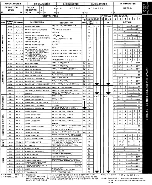
Tables 3-2 and 3-3, respectively, summarize the instruction repertoire and the mnemonic operation codes of the UNIVAC 1050 System. The instruction execution times appear in Table 3-4 on page 3-73.
2
{~"
UP-3912 Rev. 1
o
C',
"...
o
a=
I-z o
u
I-is
III
I\. = LOGICAL. AND
V = LOGICAl.. OR
CENTRAL PRDCESSDR
SECTION:• = SENTINEL. t 00 IS INTERPRETED BY THE CIRCUITRY AS 0". '* IF a = I, BIT 15:;: 0; IF a = 2. BIT lIS = I.
*
=M DESIGNATES THE § 000 IS INTERPRETED BY THE CIRCUITRY AS ala.MOST SIGNIFICANT ** 0000 IS INTERPRETED BY. THE CIRCUITRY AS 020. NOTE: SUBSCRIPT t INDICATES IMMEDIATE
CHAR. OF THE FIEL.O DATA., AS OPPOSED TO REFERENCED
DATA.
Table 3-2. Ins truction Repertoire.
TETRAD CHAR. ROW 0 CHAR. ROW 2 ROW 3 CHAR. ROW 4 CHA'R. ROW 5
•
• • • •
READ CHAR. K~~U. K~AU ADDRESS
I
BASE COUNT RECORD
Reserved
• MEMORY • cHAR":. A~~:SS
I
BASE COU NT RECORDDRUM
ADDRESS
*a = ZERO COUNT
*b = TRANSLATION TABLE ADDRESS *c = BLOCK TRANSFER COUNT *d = CHARACTER COUNTt
Figure 3-1. Layout of First Six Rows of Store
()
()
ml:.lY\\JM:T
ADDRESS ADDRESS • BASE
I
RECORD RECORDED ADDRESS
*e = LINE ADVANCE COUNT
*1 = COLUMN COUNT FOR COLUMN READER *g:: HOLE COUNT (Post-punch read and punch) t
*h = HOLE COUNT (wait and pre.punch) t
t USED ONLY BY CONTROL UNITS
•
•
*i = ROW COUNT (punch) t
*j = ROW COUNT (pre-read) t
*k = ROW COUNT FOR ROW READER *K2 = PARITY ODD LOCATION *K! = PARITY EVEN LOCATION
()
~c::
~
-p
< W
\0
...
~L
n
Cm~
2~
-I ...
:a~
:.:.0
r-~
en
'a~
:a~aen
n
m
en
en
I
a
:a
UP-3912 Rev. 1
c
3
UNIVAC 1050 SYSTEMS
CENTRAL PRDCESSDR
SECTION:OCTAL
OP CODE MNEMONIC DESCRIPTION 00 - (Unassigned)
02 - "
04 - "
06 - "
10 JR Jump Return 12 TR TRanslate
14 LC Logical Comparison 16 BCn Bit Circulate 16 BSn Bit Shilt 20 FT Fix Tetrad
22 ZS* Zero Suppress wi th asterisk Ii II 22 ZS$ Zero Suppress with Iloating
dollar sign
22 ZS Zero Suppress with no float-ing dollar sign
24 TFI Transfer From memory, In-crement destination address 24 TFR Transfer From memory,
Re-set destination address 24 TTl Transfer To Memory,
Incre-ment origin address 24 TTR Transfer To memory, Reset
origin address 26 PD PaD blanks 26 PDO PaD decimal zeros 26 CDa Compare Decimal 30 J Jump
30 JC Jump Conditi ona Ily 30 JD Jump Display 30 JE Jump if Equal 30 JG Jump if Greater 30 JHJ Halt, then Jump 30 JS Jump if Smaller 30 JU Jump if Unequal 32 JL Jump Loop 34 CC Compare Character 36 - (Unassigned) 40 XF eXternal Function 42 ST Store Tetrad 44 SC Store Character 46 BT Bring to Tetrad 50 DV DiVide
50 MPC MultiPly Cumulative 50 MPN Mu Iti P Iy N oncumu lative 52 ED EDit
52 SAa Store Arithmetic register 52 SAR Store both Arithmetic Registers 54 LP Logical Product
56 BAa Bring Alphanumeric 56 BOa Bring Decimal 60 AC Add Character 62 AMa Add to Memory 62 SMa Subtract from Memory 64 LS Logical Sum 66 ADa Add Decimal 66 SDa Subtract Decimal 70 CBa Compare Binary 72 ABa Add Binary 72 SBa Subtract Binary 74 CT Compare Tetrad 76 AT Add to Tetrad
Table 3-30. Mnemonic Operations Ordered by Operation Code.
MNEMONIC OCTAL DESCRIPTION INSTRUCTION OP CODE
ABa 72 Add Binary AC 60
•
Add Character ADa 66 Add Decimal AMa 62 Add to Memory ___ AJ ___ 76 Add to Tetrad--Sr--f ' _
-BAa Bring AiphanL1meric BCn 16 Bit Circulate BOa 56 Bring Decimal BSn 16 Binary Shift BT 46 Bring to Tetrad
---cs;;---
--TO-- CompareBinaij---CC 34 Compare Characte"rCDa 26 Compare Decimal CT 74 Compare Tetrad DV 50 DiVide
---ED---52-- E D I f
-FT 20 Fix Tetrad J 30 Jump
JC 30 Jump Conditiona Ily JD 30 Jump Display
---JE----
--TIl---
JumpiTEquaT---JG 30 Jump if Greater JHJ 30 Halt, then Jump JL 32 Jump Loop
__ JR ____
10 J!!.!!1Q.!!!!t!!r1!.. _______ JS--3D--
Jump.if SmallerJU 30 Jump if Unequal LC 14 Logical Comparison LP 54 Logical Product
LS 64
.~.Q.gJ..!:~~u.!!l..---MPC---50-- MultiPly Cumulative MPN 50 MultiPly Noncumulative PO 26 PaD blanks
PDO 26 PaD decimal zeros SAa 52 Store Arithmetic register ---SAR---c---52-- Storeboth-AfithmetTcRegiSters
SBa 72 Subtract Binary SC 44 Store Character SDa 66 Subtract Decimal
SMa 62 ~i!!.r'!.c!..f!!ll!!.. ~1!!9!y _ _ _ _
---ft----
f--T2--- Store TetradTFI 24 Transfer From memory, In-crement destination address TFR 24 Transfer From memory, Reset
destination address
- - - --12--
TRanslate---TR
TTl 24 Transler To memory, Incre-ment origin address TTR 24 Transfer To memory, Reset
origin address
---:ZST-- -22-- Zero Suppresswl1h-astefTSiI--fi II
ZS$ 22 Zero Suppress with floating dollar sign
ZS 22 Zero Suppress with no Iloating dollar sign
XF 40 e~!!r.!l.a.!£~~i~ ______
-Table 3-3b. Mnemonic Operations Ordered Alphabetically.
* The XF instruction is explained in the peripheral hardware manual fot the unit to which it pertains.
PAGE:
SEE
PAGE
3-38 40 26 29 7 -16 72 14 71 6---46
47 44 9 ___ ~IL63 10 51 54
___ ~:L
51 51 53 59 ___ ~IL
-UP-3912 Rev. 1
UNIVAC 1050 SYSTEMS '
CENTRAL PRDCESSDR
3.1 TETRAD INSTRUCTIONS
The format of a tetrad instructfon is
3
SECTION: PAGE:
~
LABEL
OPERATION
OPERANDS
:
I
,
7 11,13
18 19
30
40
4514~,
f;
,
,
v-~
,
}
~
I
0 P
M ,
T,
XI
I
II.--'"
-"
I- . / " - . . r
-
-
-
'-where
OP
is the mnemonic operation code,M is an expression designating the operand address, T is an expression naming a tetrad,
X is an expression naming an index register modifier.
.~:
If index register modification is not desired, X may be omitted, and 'an instruction may be written as follows:
LABEL
OPERATION
OPERANDS
!~
,13
30
7 11
18 19
40
4514~I
I
OP
M,
TI
II
" I \--..
~-
-
-
-
-.-..!-J
The assembler will, in this case, supply binary zeros in the index register portion of the ins truction.
3.1.1.
BRING TO TETRAD
7
Format:
8T
M, T, XFunction: Bring the four characters at Mx-3, Mx-2, Mx-l, and Mx into the specified tetrad T.
Note:
The contents of Mx-3, Mx-2, Mx-l, and Mx are not changed. Example:
Bring the contents of the four character field labeled START into tetrad 9 (IR1).
LA8EL
OPERA TlON
OPERANDS
:
~I ) 11
13
18 19
30
40
451461B T
S T A
RT,
9I
I ' II
I I1---""'"---' ...
---
-.;-----
~---
I6
UP-3912
Rev. 1
CENTRAL PROCESSOR
SECTION: PAQE:
C
3.1.2. STORE TETRAD3.1.3.
o
o
Format