United States Patent [19]
Rudi
[54] MAGNETIC TAPE RECORDER
[75] Inventor: Guttorm Rudi, Fjellhamar, Norway
[73] Assignee: Tandberg Data A/S, Oslo, Norway
[21] Appl. No.: 555,151
[22] Filed: Nov. 25, 1983[51] Int. Cl.4 ... .. GllB 5/008; G11B 15/00 [52] ... .. 360/96.5; 360/105 [58] Field of Search ... .. 360/90, 93, 95-966,
360/104405, 109; 242/192, 198-203
[56] References Cited
U.S. PATENT DOCUMENTS
3,976,262 8/1976 Kennedy ... .. 360/96.4 X
4,052,742 10/1977 Pastor . . . . . . . .. 360/96.1
4,396,963 8/1983 Wright .... .. 360/97
4,559,571 12/1985 Olmsted .. 360/105
4,573,091 2/1986 Barton ... ._ 360/93
Primary Examiner—A._ J. Heinz
Attorney, Agent, or Firm—Hill, Van Santen, Steadman &
Simpson
4,622,606
Nov. 11, 1986
[11]
Patent Number:
[45]
Date of Patent:
[57]
ABSTRACT
The magnetic tape recorder exhibits an insertion chan
nel into which a cassette containing a magnetic tape is
inserted in a longitudinal direction. A capstan driven by
a tape drive motor and a magnetic head are disposed at one side of the insertion channel. A dust cover for the
cassette is hinged out by a pivot arrangement during
closing of a cover for the insertion channel. The mag
netic head is disposed on a magnetic head carrier that is
pivotable around an axis and is coupled with the cover
for the insertion channel such that the magnetic head is pivotable into place behind the dust cover in contacting relation to the magnetic tape after said dust cover has
been opened. The cassette is locked in a de?ned work
ing position after the cover for the insertion channel is closed. For removal of the cassette, the magnetic head
is pivoted out of its operating position into an idle posi
tion as the cover for the insertion channel is opened,
whereupon the dust cover is hinged back into its closed
position.
US. Patent Nov.’ 11, 1986
Sheet 1 012
4,622,606.
US. Patent Nov. 11,1986
sheen of2
4,622,606
FIG 2
2..
4,622,606
1
MAGNETIC TAPE RECORDER
BACKGROUND OF THE INVENTION
The invention relates to a magnetic tape recorder wherein a cassette for the storage of data signals can be
placed into operative association with a magnetic head which is capable of data recording and/or playback operation. The magnetic tape contained in the cassette
can be moved past the magnetic head with use of a
capstan drive energized by a tape drive motor. Magnetic tape recorders are generally known
wherein data are recorded on a magnetic tape contained in a cassette and are read therefrom. A cassette contain ing a capstan idler and a pivotably disposed dust cover
in addition to the reels for the magnetic tape is em
ployed when recording digital data. The cassette is usually pushed into an insertion channel of the magnetic
tape recorder in a transverse direction toward the mag
netic head. The dust cover is thereby automatically opened. A tape capstan driven by a tape drive motor, and the magnetic head are disposed at the back side of the insertion channel. The tape capstan presses the mag netic tape against the capstan idler in order to drive said
tape. The magnetic head contacts the magnetic tape at
the working area released by the dust cover in order to record or read the data. Such magnetic tape recorders exhibit a relatively large width that is essentially deter
mined by the length of the cassette.
‘SUMMARY OF THE INVENTION The object of the invention is to specify a magnetic
tape recorder that is provided for digital recording of data and that exhibits particularly small dimensions.
Given the magnetic tape recorder of the type initially de?ned, this object is inventively achieved by means of
the features recited in Patent Claim 1.
The inventive magnetic tape recorder has the advan
tage that it exhibits small external dimensions despite
the employment of relatively large cassettes so that a high memory capacity is achieved with a relatively
small magnetic tape recorder. The magnetic tape re
corder can use the cassettes even though these were
originally intended for employment in magnetic tape
recorders wherein the cassette is inserted in a transverse
direction.
A relatively simple structure of the magnetic tape
recorder is achieved when the actuation of a pivot ar
rangement and the pivoting of the magnetic head to a position behind the dust cover ensues during insertion of the cassette into its ?nal operating position. It is par ticularly favorable for the insertion of the cassette into the ?nal operating position when this ensues while a cover covering the insertion channel is being closed.
An advantageous design of the pivot arrangement is
achieved when this is formed by a rotatably mounted
swivel arm and a connecting rod disposed at the inside of the insertion channel cover and when the free end of the swivel arm presses against a lever-like extension of the dust cover while the insertion channel cover is
being closed.
The pivot of the magnetic head is achieved in that the
magnetic head carrier is mounted for pivotal movement about an axis and is pivotable into its idle position when
the insertion channel cover is opened, by means of a head retraction mechanism secured to the inside of the
cover and is pivotable into its operating position when
the cover is closed by means of a spring secured to the
5 30 40 45 60 65
2
magnetic head carrier. The head retraction mechanism
is expediently designed as a tension spring. The spring
pivoting the magnetic head into its operating position is
expediently designed as a compression spring disposed
concentric to the axis of the magnetic head carrier
which exerts a torsional force on the magnetic head
carrier. The magnetic head carrier can be designed such
that it shifts the magnetic head along the axis by means
of a drive motor in order to position the magnetic head at various tracks of the magnetic tape.
In order to be able to remove the cassette from the
magnetic tape recorder after the cover has been opened, it is advantageous to provide a leaf spring at the back
end of the insertion channel, said leaf spring pushing the
cassette out when the cover is opened.
It is favorable for adjusting the cassette in a reference
position to provide pins representing reference points
for a plane of reference of the magnetic tape at the back end of the insertion channel and at the inside of the
cover.
It is advantageous for locking the cassette in its ?nal position when balls disposed on leaf springs are pro vided at the beginning and at the end of the insertion
channel, said balls pressing from below against recesses
in the cassette, and when a wedge is provided at the cover, said wedge pressing the leaf spring at the en
trance of the insertion channel in the direction toward the cassette when the cover is closed.
Since the capstan idler is disposed recessed in the cassette, it is expedient to pivotably mount the tape drive motor together with the capstan so that the cap stan rolls along the longitudinal side of the cassette as the cassette is being inserted and removed.
An exemplary embodiment of the inventive magnetic
tape recorder is explained in greater detail below with reference to the accompanying drawing sheets; and other objects, features and advantages will be apparent
from this detailed disclosure and from the appended claims.
BRIEF DESCRIPTION OF THE DRAWINGS FIG. 1 is a partial plan view of the magnetic tape
recorder; ‘
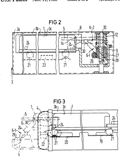
FIG. 2 is a fragmentary transverse sectional view of
the magnetic tape recorder; and
FIG. 3 is a partial fragmentary longitudinal sectional view of the magnetic tape recorder.
DETAILED DESCRIPTION
The magnetic tape recorder or transducer system
illustrated in FIG. 1 has a longitudinal insertion channel
for receiving a cassette 1. The cassette is illustrated with
dot-dash lines in its partially inserted position and with
solid lines in its ?nal operating position. The cassette 1 is inserted into the channel lateral end ?rst in a longitu
dinal direction and is held in this position against the
action of a leaf spring 2 at the back end of the insertion
channel. The housing 3 of the magnetic tape transducer
unit is provided with a hinged cover 4 which is shown
with dot-dash lines in its opened position and with solid lines in its closed position. The magnetic tape recorder
contains a pivot arrangement comprised of a swivel arm 5 and a connecting rod 6, said pivot arrangement serv
ing for the automatic opening of a dust cover 7 at a scanning location at a front end of the cassette 1. The swivel arm 5 is mounted for pivotal movement about an
4,622,606
3
the swivel arm 5 while its other end is coupled to the inside of the cover 4. A magnetic head 8 is secured to a
magnetic head carrier 9 which is pivotable around the
axis of a shaft 10. With an open cover 4, the magnetic
head 8 is situated in the position shown with dot-dash
lines as the result of the operation of a retraction mecha
nism 11 designed, for example, as a tension spring, that
is secured to the inside of the cover 4 and to the mag
netic head carrier 9. The pivot arrangement 5,6 is situ ated in the position shown with dot-dash lines when the cover is in open position.
When the cover 4 is closed, the free end of the swivel arm 5 presses against a back projection or extension 70 of the dust cover 7 and pivots said cover 7 out of a recess 10 of the cassette 1. The head retraction mecha
nism 11 is also relieved in the closed position of the cover so that a prestressed compression spring 12 dis
posed concentrically to the axis of shaft 10 can exert a
torsional force on the magnetic head carrier 9, and the magnetic head 8 is pivoted behind the dust cover 7 into its operative location where it contacts the magnetic tape 13 (as shown with solid lines in FIG. 1). The mag netic head carrier 9 is pivoted by spring 12 so that the carrier 9 engages a detent 14 and is held in this position. The magnetic head 8 is displaceable in the direction of the axis of the shaft 10 and, thus, perpendicular to the
running direction of the magnetic tape 13 upon employ
v.ment of a drive motor 15 in order to be able to position
'zthe magnetic head 8 in scanning relation to various tracks of the magnetic tape 13. The dust cover 7 is held
in its open position by a detent 15’. Said detent 15’ can also serve as a detent for the magnetic head carrier 9 in
its idle position.
A capstan idler 16 is disposed at a recess 1b in the cassette 1. The capstan 17 and the tape drive motor 18 are therefore pivotably designed with a resilient bias
toward the cassette so that the capstan 17 rolls along the long side of the cassette 1 as the cassette 1 is inserted or
removed. The tape drive motor 18 is expediently .mounted at its center of gravity for pivotal movement
- ‘about an axis 180 and the capstan 17 is biased against the cassette 1.
Leaf springs 19 and 20 provided with balls 21 press against the cassette 1 from below. The leaf spring 19 presses against the cassette 1 with a prescribed pressure whereas the leaf spring 20 presses against the cassette 1 with reduced force. When the cover 4 is completely closed, a wedge 22 presses against the leaf spring 20 so
that this presses toward the cassette 1 with the same force as the leaf spring 19. The balls 21 engage in corre sponding recesses of the cassette 1. Cooperating sur faces 23 are provided on the transducer unit at the loca tions of the insertion channel allocated to the four cor ners of the cassette 1 for the purpose of locking the
cassette in the ?nal position. Reference pins 24 are also provided for de?ning a plane of reference of the mag netic tape 13. One of said reference pins 24 is disposed at the back end of the insertion channel, whereas three
reference pins 24 are disposed at the inside of the cover
4. The cover 4 is held in its closed position by means of pins 25 at both sides of the cover 4, said pins 25 being
provided with springs.
When the cover 4 is opened, the magnetic head 8 is pivoted back into its idle position under the influence of
_ the retraction mechanism 11. Moreover, the pivot ar
rangement 5,6 again assumes the position indicated with
dot-dash lines. The leaf spring 2 pushes the cassette 1 back to the position illustrated with dot-dash lines so
20 25 35 45 50 55 65
4
that said cassette 1 can be manually removed from the
magnetic tape transducer unit.
In the cross-section through the magnetic tape re corder illustrated in FIG. 2—this being broken at the number of places for reasons of space-—the cassette 1 is shown inserted in the insertion channel. The steel balls 21 have been pressed into the corresponding recesses of the cassette under the influence of the leaf spring 22. The magnetic head 8 on the magnetic head carrier 9 is
situated in its operating position. The magnetic head
carrier is pivotable around the axis of the ?xedly mounted shaft 10. The magnetic head carrier 9 is also displaceable along the axis of the shaft 10 in order to be
able to position the magnetic head in scanning relation
to various tracks of the magnetic tape 13. The displace
ment of the magnetic head carrier 9 ensues upon em
ployment of a worm 26 driven by the drive motor 15,
said worm 26 in turn driving a worm wheel 27. The worm wheel 27 has an interior thread that interacts with an external thread on the ?xed shaft 10. Given a rotation
of the worm wheel 27, the worm wheel 27 is displaced longitudinally of the ?xed shaft 10, and in a direction
which is a function of the rotational sense of the worm
26. The compression spring 12 prevents a simultaneous rotation of the magnetic head carrier 9 and also presses the magnetic head carrier 9 against the worm wheel 27. The magnetic head carrier 9 thus follows the longitudi
nal motion of the worm wheel 27 along the shaft 10 so
that the magnetic head 8 can be positioned to various tracks of the magnetic tape 13 in this matter.
In the longitudinal section through the magnetic tape
recorder shown in FIG. 3—likewise multiply broken
for reasons of space——the cassette 1 is shown situated in
its operating position with solid lines and is locked by the steel balls 21 and by the pins 24. The wedge 22 presses against the leaf spring 20. In the illustration with
dot-dash lines, the cassette 1 is situated in the interim position with an opened cover 4. In this case, the pivot arrangement 5,6 is pivoted out and does not contact the
cassette 1.
It will be apparent that many modi?cations and varia tions may be made without departing from the scope of
the teachings and concepts of the present invention.
SUPPLEMENTARY DISCUSSION
An improved magnetic recorder having features in
common with the subject matter of the present applica tion is disclosed in German application No. P3317 720.1
?led May 16, 1983, and the disclosure of said German application is incorporated herein by reference, as illus
trating a further embodiment within the broad concepts
and teachings of the present invention.
In the embodiment of FIGS. 1 and 2 herein, and in the embodiment of said German application the cassette is loaded longitudinally into a tunnel-like channel. A tape path between the reels of the cassette extends along a long side of the cassette. At this tape path there is a ?rst lateral opening forming a drive location. The cas sette is recessed (recess 1b) at this drive location to
receive the tape drive capstan. In a fully rewound con
dition of the tape, a tape leader may close this ?rst lateral opening. A second lateral opening in the cassette is at a transducing location along the tape path, and here the cassette is recessed (at 10) to accomodate the active position of the magnetic head which is to be trans versely indexed so as to be placed in scanning relation
to any of a multiplicity of side by side channels on the
4,622,606
5
In each embodiment an initial closing movement of a cassette retaining cover or actuator (cover 4) actuates a pivot arrangement coupled with the cover so as to swing the dust cover (dust cover 7) through a dust
cover path which is clear of the idle position of the magnetic head. Further closing movement of the retain
ing cover now results in movement of the cassette fur ther into the insertion channel as well as movement of
the magnetic head toward its operative position. In
order to provide a desired compactness of the tape
transducer unit in the illustrated embodiments, the idle
position of the magnetic head may be suf?ciently close
to the insertion channel so that the dust cover could not
move from its closed position to its open position with the cassette fully inserted into the insertion channel.
Thus in each illustrated embodiment, a control means is
provided which is responsive to closing of the cassette
retaining cover to move the dust cover to its open posi
tion before the cassette has been fully inserted into the insertion channel. In this way, the magnetic head does not prevent the opening of the dust cover, even though the idle position of the head is close to the insertion channel.
While it is conceivable that the magnetic head could be parked at an extreme position in the axial direction
parallel to its pivot axis during loading of the cassette
such that the dust cover could swing at a level e.g.
above the level of the magnetic head and its carrier, this would require a greater extent of axial travel of the magnetic head than that required merely to scan the
different channel on the record tape and thus imply a
less compact housing for the transducer unit.
Referring to the embodiment of FIGS. 1 and 2 herein, the dust cover 7 may have its extension arm 7a pivotally
mounted as indicated at 28 in FIG. 1 so that the dust cover 7 cannot return to the closed position, even with
the head 8 in its idle position (indicated at 8-1 in FIG. 1) until leaf spring 2 shifts the cassette a substantial dis tance toward its ejected position (shown at 1-1 in FIG. 1). Once the dust cover 7 is disengaged from latch 15'
(e.g. as a result of the movement of the cassette to
ejected position 1-1 under the impetus of leaf spring 2)
a torsion spring at the pivot axis 28 may return the dust
cover 7 to its closed position.
In FIG. 2, the connecting rod is indicated at 6-1 in a
initial position with cover 4 open, and is indicated at 6-2 in a ?nal position with he cover fully closed. As an example, a retainer is indicated at 29 in FIGS. 2 and 3
for coupling the connecting rod 6 with cover 4, and a retainer 30 is indicated for coupling the connecting rod
6 with the swivel arm 5.
As shown in FIGS. 2 and 3, the housing 3 provides
?xed walls at 3a, 3b which de?ne a ?xed tunnel-line ensertion channel into which the cassette 1 is inserted
edgewise in a horizontal orientation. The connecting
rod 6, swivel arm 5 and extension 70 form a control means which engages the dust cover 7 as cover 4 is closed while the cassette is in an initial position such as 1-1, FIG. 1. As the cassette 1 is advanced toward its
fully inserted position, an edge 7b on the dust cover may
engage with a ?xed part of latch 15' so that the dust cover 7 is held clear of head 8 as indicated in FIG. 1 to
freely accomodate indexing movement of the head 8. When the cover 4 is opened, the latch 15’ retains dust
cover 7 in its open position shown in FIG. 1 as the head
8 is retracted to itsidle position 8-1, FIG. 1. As leaf spring 2 moves the cassette to position 1-1, FIG. 1, the edge 7b disengages from latch 15' and the dust cover 7
25
30
45
65
6
is restored to its closed position e.g. by a torsion spring on pivot pin 28 similar to torsion spring 12 which acts
on the head carrier 9.
When the cassette 1 has been removed from housing
3 and the cover 4 returned to its closed position (e.g. by tension spring 11), the frictional force of latch 15’ on the
head carrier 9 may be suf?cient to dampen the return
movement of the head 8 under the impetus of torsion spring 12. Additionally, latch 15’ may latch the head carrier 9 at the idle position and require a de?nite (e.g. manual) release before a scanning operation by means of
the magnetic head 8 can be set in progress. In any event opening of the cover 4 assures that the head 8 will be in the retracted position 8-1 before a new cassette is in
serted into the insertion channel.
The upper wall 3b may provide an interior horizontal
surface 3c which slightly above the ?nal position of
cassette 1 with cover 4 fully closed. I claim as my invention:
1. A magnetic tape transducer system, comprising: a
tape transducer unit; a cassette having a front end and
?rst and second lateral ends,
a magnetic tape movable along a tape path past a scanning location at the front end of the cassette,
and a dust cover which is pivotable between a
closed position covering said scanning location and
an open position exposing said scanning location;
the tape transducer unit having a magnetic head for
scanning of said magnetic tape at said scanning
location, a tape drive motor, and a capstan driven
by said tape drive motor positioned to drive the
magnetic tape along the tape path; the tape trans
ducer unit having an insertion channel means for
receiving said cassette with the ?rst lateral end
leading and wherein the ?rst lateral end is adjacent
a back end of the channel means when the cassette
is fully inserted; the magnetic head and the capstan
being disposed at a side of said insertion channel
means adjacent the cassette front end when the
cassette is fully inserted, insertion means for insert ing the cassette into a ?nal position in the channel
means; means for pivoting said dust cover to its
open position as the cassette is being inserted by the
insertion means, a magnetic head carrier means
carrying the magnetic head and pivotably mounted
to the transducer unit; and means coupling the head
carrier means to the insertion means for swinging
the magnetic head from an idle position into scan ning relation with the magnetic tape at the scan ning location behind the dust cover simultaneously‘
as the dust cover is pivoted from its closed to open
positions during insertion of the cassette by the
insertion means. i
2. A magnetic tape transducer system as claimed in
claim 1 wherein the head carrier means pivots about an
axis perpendicular to a direction of tape transport of the cassette so that the magnetic head swings in a horizontal plane perpendicular to the axis of the dust cover toward
the scanning location.
3. A magnetic tape transducer system as claimed in
claim 1 wherein said insertion means comprises a cas
sette positioning cover means movable for closing the insertion channel means, and effecting the insertion of the cassette into its ?nal operating position and said means for pivoting the dust cover being directly cou
pled to said cassette positioning cover means.
4. A magnetic tape transducer system as claimed in
4,622,606
7
sette positioning cover means for closing the insertion channel means as the cassette is inserted in its ?nal posi
tion therein; the pivoting means comprising a rotatably
mounted swivel arm and a connecting rod connected with the swivel arm and coupled with an inside of the cassette positioning cover means; and a free end of the swivel arm being positioned to press against a lever-like extension of the dust cover as the cassette positioning cover means is being closed.
5. A magnetic tape transducer system as claimed in
claim 1, wherein said insertion means comprises a cas sette positioning cover means for closing the insertion channel means and for inserting the cassette into its ?nal
position; said coupling means comprising ?rst spring
means coupled with said head carrier means for effect
ing shifting movement of the magnetic head as the
cover means is opened, said ?rst spring means being coupled with an inside of the cassette positioning cover
means; and second spring means for effecting shifting of the magnetic head carrier means between the idle posi
tion with said magnetic head clear of said scanning
location and an active position where the magnetic head is held at said scanning location in response to opening
and closing of said cassette positioning cover means.
6. A magnetic tape transducer system as claimed in claim 5 wherein the ?rst spring means is comprised of a tension spring which is placed under tension to retract the head from the scanning location when the cassette
' positioning cover means is opened.
7. A magnetic tape transducer system as claimed in
claim 5 wherein said second spring means comprises a
compression spring disposed concentrically to a pivot
axis of the magnetic head carrier means and which
exerts a torsional force on the magnetic head carrier
means urging the head toward said scanning location.
8. A magnetic tape transducer system according to
claim 7 including a drive motor means coupled with the
magnetic head carrier means for effecting displacement i of the magnetic head longitudinally along the pivot axis
against the action of said compression spring.’
'~ *9. A magnetic tape transducer system as claimed in claim 1 wherein said insertion means comprises a cas sette retaining cover means for movement to a closed
position to position and retain the cassette in said inser
tion channel means in its ?nal position, and for move ment to an open position to accommodate removal of the cassette from the insertion channel means; and a leaf spring means at the back of the insertion channel means,
said leaf spring means pushing the cassette to a position protruding from the insertion channel means when the
retaining cover means is shifted to its open position.
10. A magnetic tape transducer system as claimed in
claim 1, wherein said insertion means comprises a cas sette positioning cover means for closing said insertion channel means to position a cassette therein and refer
ence pin means representing reference points for a plane of reference of the magnetic tape at the back end of the
insertion channel means and at an inside of the cassette positioning cover means for effecting a ?nal positioning of said cassette when the cover means is completely
closed.
11. A magnteic tape transducer system as claimed in
claim 1.wherein said insertion means comprises a cas sette positioning cover and means which is movable to close the insertion channel means as the cassette is being
inserted therein, a wedge being provided at the posi
tioning cover means, a leaf spring being provided with
steel balls and positioned to be engageable by said
5
25
45
65
8
wedge as the positioning cover means is closed for
pressing against the cassette from beneath the cassette
with increased pressure after the positioning cover means is closed, so that the steel balls engage in corre sponding recesses of the cassette.
12. A magnetic transducer system according to claim
1 wherein said cassette has a lateral opening at said
scanning location selectively receiving said dust cover
and said magnetic head, said insertion means comprising
cassette positioning means shiftable from an open posi tion providing access to said insertion channel means to
a closed position closing said insertion channel means,
and said said means for pivoting the dust cover being
engaged by said cassette positioning means to shift said dust cover to its open position during insertion of the cassette into said insertion channel thereby to prevent
obstruction of such movement of the dust cover be
cause of the position of the magnetic head.
13. A magnetic transducer system according to claim 1, wherein said transducer unit has a ?xed upper wall
providing said insertion channel means in the form of a
horizontally extended tunnel with an open end, the cassette being inserted edgewise in a horizontal plane
through the open end and partially into said tunnel, and
said insertion means being manually shiftable to effect
completion of the edgewise movement of the cassette
into its ?nal position in the tunnel.
14. A magnetic transducer system according to claim
13 wherein said means for pivoting shifts said dust cover to its open position before the completion of edgewise movement of the cassette into said tunnel,
thereby to enable clearance of the dust cover from the
magnetic head and its carrier means during such shifting
of the dust cover to its open position so as to allow the
magnetic head to pivot to its operating position behind
the open dust cover.
15. A magnetic tape transducer system for use with a
cassette containing a tape and having a drive opening and a tape scanning location protected by a pivotable
dust cover at a front end, and ?rst and second lateral
ends substantially perpendicular to the front end, com
prising:
an insertion channel means for receiving the cassette
?rst lateral end ?rst, the insertion channel means having a back end adjacent the inserted ?rst lateral
end when the cassette is fully inserted and a front side parallel to an insertion direction of the cas sette; a drive means positioned at said front side of the insertion channel means for interaction with the cassette drive opening and a magnetic head assem
bly also positioned at said front side positioned to interact with the scanning location;
a manually activatable insertion means for inserting the cassette into the channel means;
means coupled to said insertion means for pivoting the pivotable cassette dust cover from a closed position to an open position as the cassette is in
serted into the insertion channel means; and
means coupled to the insertion means for simulta
neously moving the magnetic head assembly as the
dust cover is pivoted such that the magnetic head
assembly is positioned directly at the scanning lo
cation.
16. A system according to claim 15 wherein the
means for moving the magnetic head assembly pivots the magnetic head assembly into position behind the
dust cover when the dust cover swings into the open
4,622,606
17. A system according to claim 15 wherein the
means for pivoting the dust cover comprises a swivel arm having a free end positioned to press against a lever-like extension of the dust cover.
18. A magnetic tape transducer system for use with a cassette containing a tape having a drive opening and a
tape scanning location protected by a pivotable dust
cover at a front end, and ?rst and second lateral ends
substantially perpendicular to the front end, compris
mg:
an insertion channel means for receiving the cassette ?rst lateral end ?rst, the insertion channel means
having a back end adjacent the inserted ?rst lateral
end when the cassette is fully inserted and a front side parallel to an insertion direction of the eas sette, a drive means being positioned at said front side of the insertion channel means for interaction
with the cassette drive opening, and a magnetic head assembly also positioned at said front side
positioned to interact with the scanning location;
a manually activatable insertion means for inserting
the cassette into the channel means;
means for pivoting the pivotable cassette dust cover
between a closed position and an open position as
the cassette is being inserted into the insertion
channel means;
means coupled to the insertion means for simulta
neously moving the magnetic head assembly as the
dust cover is being pivoted from its closed to open
positions such that the magnetic head assembly is
pivoted from an idle position to an operating posi
tion as the insertion means is inserting the cassette
into the insertion channel means; and
said means for moving the magnetic head assembly being pivotable about an axis which is perpendicu
lar to a running direction of the tape so that the
head assembly can swing from the idle position to
the operating position.
19. A system according to claim 18 wherein said
insertion means comprises a cover, said means for pivot ’ ing comprising a swivel arm, means being provided for
de?ecting the swivel arm so as to engage a lever portion of the dust cover on the cassette as the cover is being
10
20
25
35
40
45
50
55
60
65
10
closed, and said means for moving the magnetic head assembly including spring means connected to the
cover such that as the cover closes off the insertion
channel means, the magnetic head pivots toward the
operating position as the swivel arm engages the cas sette dust cover and opens it.
20. A magnetic tape transducer system for use with a cassette containing a tape having a drive opening and a
tape scanning location protected by a pivotable dust
cover at a front end, and ?rst and second lateral endssubstantially perpendicular to the front end, compris
ing:
an insertion channel means for receiving the cassette
?rst lateral end ?rst, the insertion channel means having a back end adjacent the inserted ?rst lateral
end when the cassette is fully inserted and a front side parallel to an insertion direction of the cas
sette, a drive means being positioned at said front
side of the insertion channel means for interaction
with the cassette drive opening, and a magnetic head assembly also positioned at said front side
positioned to interact with the scanning location;
a manually activatable insertion means for inserting
the cassette into the channel means; -
means directly driven by the insertion means for piv oting the pivotable cassette dust cover being a closed position and an open position simulta neously as the cassette is being inserted into the
channel means by the insertion means;
means coupled to the insertion means for simulta
neously moving the magnetic head assembly as the
dust cover is being pivoted from its closed to open
positions such that the magnetic head assembly is
pivoted from an idle position to an operating posi
tion as the insertion means is inserting the cassette
into the channel means; and
said means for moving the magnetic head assembly being pivotable about an axis which is perpendicu
lar to a running direction of the tape so that the
head assembly can swing from the idle position to