University of Twente
EEMCS / Electrical Engineering
Control Engineering
Real-Time Network for Distributed
Control
Yuchen Zhang
M.Sc. Thesis
Supervisors prof.dr.ir. J. van Amerongen
dr.ir. J.F. Broenink dipl.ing. B. Orlic Ir. P.M. Visser August 2005 Report nr. 031CE2005 Control Engineering
EE-Math-CS University of Twente
Summary
Nowadays, complex control systems, e.g. for industrial automation, are evolving from
centralized architectures to distributed architectures. To design a distributed control
system, a critical issue is to lay out a hard real-time communication infrastructure. To
this end, two kinds of solutions can be categorized from contemporary approaches:
the hardware-based solution and the software-based solution. Compared with the
hardware-based solution, the software-based solution is generally more cost-effective,
adaptable and extendable. Therefore it is more widely applied, especially in
laboratory.
FireWire is a high performance serial bus for connecting heterogeneous devices.
Though firstly targeted for consumer-electronic applications, many of FireWire’s
features make it well fit in industrial and laboratorial context. In this MSc assignment,
following the general principles of the software-based solution, the Real-Time
FireWire Subsystem (RT-FireWire) in Linux/RTAI has been designed and
implemented. RT-FireWire provides a customizable and extensible framework for
hard real-time communication over FireWire. Via performance benchmarking, it has
been shown that the transaction latency on RT-FireWire is limited to a certain range
that is usable for distributed control applications, whether the system is under heavy
load or not.
Ethernet Emulation over FireWire (Eth1394) has been implemented on RT-FireWire
as a highlevel module in the application layer. Via Eth1394, RT-FireWire can be
connected to another real-time software framework RTnet, which implements
real-time networking on the IP layer. Therefore, FireWire has been introduced as a
new medium alternative to Ethernet for real-time IP networking. The benchmarking
on Eth1394 and Ethernet shows that the real-time performance of both is comparable.
The real-time networking support provided by RT-FireWire has been integrated to a
toolchain for controller design and verification. The toolchain is developed at Control
Engineering Group of University of Twente. By using this toolchain with the newly
added networking support, a controller that has been designed and verified in
simulation can now be easily deployed into multiple nodes. For demonstration, a
simple but real-life distributed control system has been built by using this toolchain
and FireWire. The measurement results on that system proofs that, FireWire, with
RT-FireWire steering on it, can be used as a fieldbus for a distributed control
application.
With this report, I finished my MSc study at University of Twente. I would like to give my thanks to all the people who helped me during these two years, especially during my thesis work in last 11 months.
I would like to thank Jan Broenink, Bojan Orlic and Peter Visser for their supervising on my work. Also, I would like to thank Marcel Groothuis for his help and suggestions to my work.
I have my special thanks to the Open Source community, especially to Jan Kiszka, the project leader of RTnet. Thanks for all his explanations about RTnet, and the wonderful discussions that I had with him via Email.
I would like to thank my parents also. Without their support, it would not be possible for me to study abroad.
Last but not least, I would like to thank all my friends in the Bible Study group. Thanks for their prayers.
Zhang Yuchen
Table of Contents
1 INTRODUCTION ...1
1.1 BACKGROUND...1
1.1.1 Real-Time Computer System...1
1.1.2 Centralized Architecture vs. Distributed Architecture ...1
1.1.3 Hard Real-Time Networking in the Distributed Architecture...2
1.2 RESEARCH CONTEXT...2
1.3 ASSIGNMENT...3
1.4 INITIAL DECISIONS...3
1.4.1 FireWire...3
1.4.2 Linux ...4
1.5 REPORT OUTLINE...4
2 INTRODUCTION TO FIREWIRE AND ITS SUBSYSTEM IN LINUX ...5
2.1 INTRODUCTION...5
2.2 OVERVIEW OF FIREWIRE...5
2.2.1 Bus Topology...5
2.2.2 Data Transfer Modes ...6
2.3 FIREWIRE PROTOCOL LAYERS...7
2.3.1 Physical Layer ...7
2.3.2 Link Layer ...8
2.3.3 Transaction Layer ...8
2.3.4 Bus Management Layer...9
2.4 PROTOCOL OVERHEAD AND TRANSMISSION TIMING...10
2.4.1 Asynchronous Transaction...10
2.4.2 Isochronous Transaction ...12
2.5 LINUX FIREWIRE SUBSYSTEM...14
2.5.1 Introduction ...14
2.5.2 System Overview...14
2.5.3 Performance Benchmarking on Linux FireWire Subsystem...16
3 REAL-TIME FIREWIRE SUBSYSTEM...23
3.1 INTRODUCTION...23
3.2 FUNDAMENTAL OF RT-FIREWIRE...23
3.3 SETTLING RT-FIREWIRE IN RTAI ...24
3.3.1 System Overview...24
3.3.2 Architecture and Task Composition...25
3.3.3 Hardware Operation Layer ...26
3.3.4 Protocol Processing Layer ...27
3.3.5 Application Layer ...28
3.4 REAL-TIME MEMORY MANAGEMENT...29
3.4.1 Common Packet Buffer Structure...29
3.4.3 Packet Buffer Pool...30
3.5 OTHER DESIGN ISSUES IN RT-FIREWIRE...31
3.5.1 Real-Time Procedure Call ...31
3.5.2 Real-Time Packet Capturing...32
3.6 PERFORMANCE BENCHMARKING ON RT-FIREWIRE...33
3.6.1 Measurement Results...34
3.6.2 Discussion and Conclusion...38
4 REAL-TIME IP NETWORK OVER RT-FIREWIRE ...39
4.1 INTRODUCTION...39
4.2 ETHERNET EMULATION OVER RT-FIREWIRE...39
4.2.1 “IPover1394” Spec ...39
4.2.2 Minimum Requirements to be IP-capable ...39
4.2.3 Addressing Mechanism ...39
4.2.4 Address Resolution Protocol ...41
4.2.5 Implementation of Eth1394 ...43
4.3 STACKING RTNET OVER RT-FIREWIRE...43
4.3.1 Introduction about RTnet...43
4.3.2 Application Programming Interface based on RTnet...43
4.3.3 Media Access Control...44
4.4 TEST BENCH...44
4.4.1 Bench Settling and Measurement Results ...44
4.4.2 Discussion...46
5 INTEGRATION TO DESIGN TOOLCHAIN AND DEMONSTRATION ...47
5.1 INTRODUCTION...47
5.2 INTEGRATION TO THE DESIGN TOOLCHAIN...47
5.2.1 MSC Toolchain...47
5.2.2 Adding Networking Support to MSC Toolchain ...47
5.3 DEMONSTRATION...49
5.3.1 Plant and Controller...49
5.3.2 Performance Comparison ...51
5.4 DISCUSSIONS...52
6 CONCLUSIONS AND RECOMMENDATIONS ...55
6.1 CONCLUSIONS...55
6.2 RECOMMENDATIONS...55
SHORT-TERM...55
Raw Interface on RT-FireWire layer ...55
Media Access Control in RT-FireWire...56
LONG-TERM...56
Stacking one or more middleware frameworks onto RT-FireWire ...56
Porting New Hardware Drivers to RT-FireWire ...56
Real-Time Vision Control over RT-FireWire...56
PORTING TO FUSION...57
Changes of the Code Generation Template...57
Change to Stack Daemon...58
Connection Objects...58
ADDING THE DISTRIBUTED CONTROLLER DEPLOYMENT...59
APPENDIX 2 NON REAL-TIME FACTORS IN LINUX FIREWIRE SUBSYSTEM ...61
LAYERED ARCHITECTURE AND TASK HANDOVER LATENCY...61
MEASURING OF TASK HANDOVER LATENCY IN LINUX FIREWIRE SUBSYSTEM...62
Conclusion ...63
APPENDIX 3 PRACTICAL INFORMATION ABOUT RT-FIREWIRE ...65
APPENDIX 4 PUBLICATION TO 10TH IEEE INTERNATIONAL CONFERENCE ON EMERGING TECHNOLOGIES AND FACTORY AUTOMATION ...67
1 Introduction
1.1 Background
1.1.1 Real-Time Computer System
A real-time computer system is a computer system in which the correctness of the system behavior depends not only on the logical results of the computations, but also on the physical instant at which these results are produced.[Kopetz, 1997 ] A real-time computer system often co-exists with the other two subsystems, as shown in Figure 1-1.
Figure 1-1 Real-Time Computer System and its Workaround
A real-time computer system must react to the stimuli from the controlled object (or the operator) within a time interval. The instant at which a result must be produced is called a deadline. If a catastrophe could result if a deadline is missed, the deadline is called hard. Otherwise it is soft. A real-time computer system that must meet at least one hard deadline is called a hard real-time computer system, or a safety-critical real-time computer system. If no hard deadline exists, then the system is called a soft real-time computer system.
The design of a hard real-time computer system is fundamentally different from the design of a soft real-time computer system. While a hard real-time computer system must sustain a guaranteed temporal behavior even under peak system load and any possible fault conditions, it is permissible for a soft real-time computer system to miss a deadline occasionally.
1.1.2 Centralized Architecture vs. Distributed Architecture
The architecture of real-time computer system can be centralized or distributed. A distributed real-time computer system consists of a set of nodes and a communication network that interconnects these nodes. Compared with the centralized architecture, the distributed architecture appears as a more preferable alternative for the implementation of hard real-time system. Several arguments are:
z In many engineering disciplines, large systems are built by integrating a set of well-specified and tested subsystems. It is important that properties that have been established on the subsystem level are maintained during the system integration. In the distributed architecture, such a constructive approach is much better supported, compared with centralized architecture.
z Almost all large systems evolve over an extended period of time, e.g. some years or decades. Therefore a scalable and extensible system is strongly desired. To deploy a scalable and extensible system, a distributed architecture is essential to provide the necessary framework since:
introduces additional processing power to the system.
II. If the processing power of a node has reached its limit, a node can be transformed into a gateway node to open a way to a new cluster. The interface between the original cluster and the gateway node can remain unchanged (Figure 1-2).
z Most of the critical real-time systems demand fault-containment or fault-tolerance, which means the system should continue functioning despite the occurrence of faults. To this end, only the distributed architecture gives the possibility to implement fault-containment or fault-tolerance via distributing the system functions to different nodes or replicating the function of a certain node to another.
Figure 1-2 Transparent expansion of a node into a new cluster
1.1.3 Hard Real-Time Networking in the Distributed Architecture
To deploy a real-time computer system with a distributed architecture, one important issue is to lay out a hard real-time communication infrastructure, so-called fieldbus. To this end, two kinds of solutions can be categorized from contemporary design approaches.
z To use specifically adapted or designed hardware components to deploy a hard real-time network. These components may be real-time switches, network adapters with high innate intelligence or even fundamentally revised network controllers. By using these hardware components, a hard real-time system can be built. However, since this solution is fully implemented in hardware, a lot of effort and investments is needed. Moreover, the adapted or newly designed hardware can not be easily changed or extended.
z Instead of using hardware-based solution, the more flexible software-based solution can be chosen. In this solution, the standard, relatively cheap hardware components can be chosen, e.g. Ethernet, USB, and FireWire. Above these hardware components, a real-time, deterministic software stack (e.g. real-time operating system, real-time implementation of the network protocol stack, etc) should be built, which can steer the hardware to meet the real-time behavior requirements. The strength of this software-based solution is that, it does not need too much effort and investment for design and implementation, and one solution can be easily adapted for another problem or moved to another platform.
1.2 Research
Context
methodology for embedded control software; CSP-based concurrent programming; fieldbus-connected embedded control systems and hardware-in-the-loop simulation for embedded control system, etc.
Narrowed down to the research on distributed control systems, the main work is leaded by two PhD projects:
z CSP-channels for field-bus interconnected embedded control systems. It deals with hard real-time control using several co–operating processors in networked environments. The network itself is embodied by an industrial field bus, which are investigated with respect to real-time performance. During the work by previous students, CAN [Ferdinando, 2004], USB, Ethernet [Buit, 2004], FireWire [Zhang, 2004] and Profibus [Huang, 2005] has been investigated with respect to their suitability for use in real-time context.
z Boderc(Beyond the Ordinary: Design of Embedded Real-time Control): Multi-agents and CSP in Embedded Systems. In this project, a hardware-in-the-loop setup has been built by [Groothuis, 2004] to test distributed controllers with simulation model of various plants. In this setup, the communication channel between controllers is deployed on CAN.
1.3 Assignment
Following the second approach in 1.1.3, the objective of this MSc assignment is to adopt a standard, relatively cheap networking hardware component for deploying the hard real-time network in distributed control systems. Around the main goal, challenges exist on several aspects:
z The existing software on that hardware should be adjusted or even re-designed, so the hardware can be steered to behave in a deterministic way.
z The adjusted or re-designed software should be easily adaptable and extensible.
z Resource-constraint situation should be taken into account, like system with in-adequate memory.
z The adjusted or re-designed software should provide a friendly interface, which eases the development of applications (e.g. controllers) on it.
1.4 Initial
Decisions
1.4.1 FireWire
1.4.2 Linux
Linux, an Open Source operating system kernel, is well known for its open structure, modular design and easy adaptability. In this assignment, Linux is chosen to be the Operating System kernel. Thereby, the FireWire Subsystem in Linux is taken as the starting point for investigation and implementation.
1.5 Report
Outline
Chapter 2 firstly gives a detailed description about FireWire, including its characteristic on various aspects, e.g. bus topology, data transfer modes, etc. Secondly, the FireWire subsystem in Linux is described and the measurement results concerning its suitability for use in real-time is presented.
Chapter 3 presents the implementation of the Real-Time FireWire Subsystem (RT-FireWire), including the architecture, core components and protocol adaptation. Secondly, the measurement results concerning RT-FireWire’s suitability for use in real-time is given, and compared with the results on the Linux FireWire Subsystem.
Chapter 4 presents the implementation of deploying real-time IP network over RT-FireWire. Secondly, the results of performance measurement on IP over FireWire is given, and compared with the performance of IP over Ethernet.
Chapter 5 presents the integration of RT-FireWire’s networking support into a complete toolchain for design and verification of controllers. Based on the integration, a demonstration of using this toolchain for deploying a simple but real-life distributed control system is shown. The result of the demonstration is also presented.
2 Introduction to FireWire and Its Subsystem in Linux
2.1 Introduction
This chapter first starts with a detailed description of FireWire, including the overview of bus topology, data transfer modes, the layered protocol structure, and a literature research concerning the protocol overhead and the transmission timing on FireWire. Then, the pointer goes to FireWire subsystem in Linux: the software architecture is introduced and the test bench to measure the suitability of using this subsystem in real-time is presented. Based on the measurement, the conclusion about whether FireWire subsystem in Linux is suitable for use in real-time is reached.
2.2 Overview
of
FireWire
2.2.1 Bus Topology
The IEEE 1394 specification defines the serial bus architecture known as FireWire. Originated by Apple Computer [Apple], FireWire is based on the internationally adopted ISO/IEC 13213 specification [IEEE, 1994]. This specification, formally named "Information technology - Microprocessor systems - Control and Status Registers (CSR) Architecture for microcomputer buses," defines a common set of core features that can be implemented by a variety of buses. IEEE 1394 defines serial bus specific extensions to the CSR Architecture.
The bus topology of FireWire is tree-like, i.e. non-cyclic network with branch and leaf nodes, for typical topology see Figure 2-1
Figure 2-1 Example FireWire Network
Configuration of the bus occurs automatically whenever a new node is plugged in. It proceeds from leaf nodes (those with only one other node attached to them) up through the branch nodes. A bus that has three or more nodes attached will typically, but not always, have a branch node become the root node (e.g. Digital VCR in Figure 2-1).
2.2.2 Data Transfer Modes
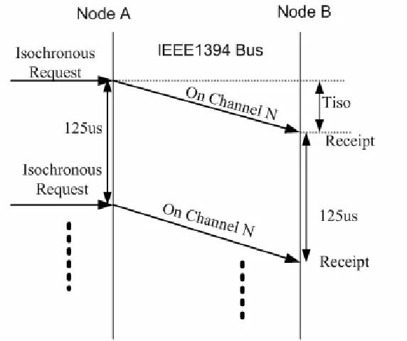
For data transfer on FireWire, two different types of packets are used: asynchronous packets for reliable, receipt-confirmed data, and isochronous packets for time-critical, unconfirmed data. A mix of isochronous and asynchronous transactions is performed across the serial bus by sharing the overall bus bandwidth. Notice that the bus bandwidth allocation is based on 125µs intervals, so called the FireWire transaction cycle, as shown in Figure 2-2.
Figure 2-2 FireWire Transaction Cycle
The isochronous transfer mode is particularly suitable for the transmission of time-critical data in real time, e.g. for video or audio. It guarantees a firm bandwidth and sends packets in a fixed clock pulse (every 125µs). The packets are not addressed to individual nodes but are separately marked by a channel number. Because late data are unusable for time-critical applications, no acknowledgment of receipt is sent and incorrect packets are not resent. Asynchronous packets are sent peer-to-peer from one node to one or all other nodes. In the packet header the address of the destination node or nodes is indicated, as is the memory address, to which the data in the packet refer. With receipt of an asynchronous packet, an acknowledgment of the receiver node is sent as proof that the packet arrived. The speed of data transmission and associated maximum packet size of asynchronous and isochronous packets are listed in Table 2-1.
Cable Speed
Maximum Size (Byte) of
Asynchronous Packet
Maximum Size (Byte) of
Isochronous Packet
100Mb/s 512 1024
200Mb/s 1024 2048
400Mb/s 2048 4096
Table 2-1 Transmission Speed and Packet Size on FireWire
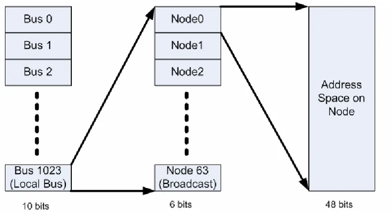
of 64 nodes per bus. This gives a 64-bit mapped address, to support 16-Exabytes in total. The illustration is given in Figure 2-3. See [Anderson, 1999] for more a detailed description.
Figure 2-3 Address Space on FireWire
2.3 FireWire Protocol Layers
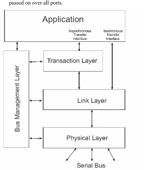
Four protocol layers are defined in FireWire, in order to separate its complexity in the several levels of abstraction and hence simplify the implementation of hardware and software. Each layer has associated set of services defined to fulfill its role, e.g. to support certain part of data transfer transactions and bus management, as shown in Figure 2-4.
2.3.1 Physical Layer
The Physical Layer is the hardware used to bridge between a local FireWire node and the whole network. This Layer has the following tasks:
z defines connectors and transmission medium
z performs bus initialization (configuration) after each Bus Reset
z manage the possession of the bus (bus arbitration)
z performs data synchronization
z performs coding and decoding of data messages
z determine signal level
On the Physical Layer, three different situations can result:
z The Physical Layer of a node receives a packet that is targeted to another node. In this case, the packet is passed further over all ports, except the one from which it was received.
case of an isochronous transmission).
z The sending packet is issued from the Link Layer of local node. In this case the packet is passed on over all ports.
Figure 2-4 Structure of the 4-layer Model
2.3.2 Link Layer
The Link Layer is located between the Physical Layer and the Transaction Layer. It performs tasks related to sending and receiving asynchronous and isochronous packets.
For a received packet, the Link Layer is responsible for checking received CRCs to detect any transmission failure; for packet to be sent, it is responsible for calculating and appending the CRC to the packet. The Link Layer examines the header information of the incoming packet and determines the type of transaction that is in progress. For asynchronous transaction, the data packet is then passed up to the transaction layer. For isochronous transaction, the transaction layer is not used and therefore the Link Layer is directly responsible for communicating isochronous data to application.
2.3.3 Transaction Layer
The Transaction Layer is only responsible for the asynchronous operations Read, Write, and Lock. By means of these operations the access of the memory area (Figure 2-3) is possible.
divides the transmission actions into individual sub-actions and handles these independently.
For these tasks as well as for the bus access management (bus arbitration) and the data synchronization, the Transaction Layer uses the following services of the Link Layer:
z Request Service (request to start a transfer)
z Indication Service (acknowledgment to the request)
z Response Service (response to the request)
z Confirmation Service (acknowledgment to the response)
2.3.4 Bus Management Layer
Each node has a Bus Management Layer which controls the bus functions in the different layers. Beyond that, the Management Layer makes a multitude of functions available concerned with the management of the power supply and the bus configuration. The actual functionality depends on the abilities of the nodes involved. However, the functions for automatic configuration must be present for all nodes.
The Bus Management is responsible for a set of tasks:
z assigning channel numbers and bandwidth allocation for isochronous transfers
z guaranteeing that, the nodes that get their power supply via the bus cable have sufficient power available
z adaptation of certain timing settings depending on the bus topology to increase the data flow-rate over the network
z supporting services, that allow other nodes to request information about topology and speed conditions
It is not necessary that all specified tasks are assigned to only one node. Rather these tasks are summarized in three global roles and during the configuration phase, efficiently divided among the attached nodes. Depending on the supported level of bus management functionality, three states based on presence/absence of the three corresponding roles are differentiated:
z "Non Managed"
A non-managed bus possesses only one "Cycle-Master" and fulfills the minimum management requirements of an IEEE 1394-Bus. In each FireWire transaction cycle, the "Cycle Master" initiates the start of the bus cycle by sending cycle start message.
z "Limited Managed Bus with Isochronous Resources Manager"
Such a bus contains an "Isochronous Resources Manager" (IRM) in addition to the "Cycle Master". The bandwidth allocation on the bus can get managed by the IRM.
z "Fully Managed Bus"
information about the bus topology ("Topological Map") and the transmission rates between any two nodes ("Speed Map"). In this way the maximum data transmission rate can be determined for each cable distance and the bus can be optimized.
2.4 Protocol
Overhead
and Transmission Timing
This section, one step deeper is taken to analyze the protocol overhead introduced by FireWire’s packet structure and to determine the transmission timing on FireWire.
2.4.1 Asynchronous Transaction
Three different asynchronous transactions are used:
z Read
z Write
z Lock
With the Read operation, data will be read from the memory area of a node. With the Write operation, data can be written into the memory area of a node. The Lock operation is a mechanism, which allows/disallows a "protected" operation[Anderson, 1999].
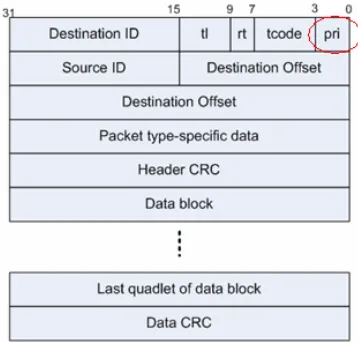
An asynchronous packet consists of header and data, see Figure 2-5 for write request packet format and Figure 2-6 for the response. See Table 2-2 for description of each component.
As can be seen from above, the protocol overhead in FireWire asynchronous write request is 24bytes, i.e. 24 extra bytes needs to be transferred along with the application data. Besides, the asynchronous write response is 16byte. Both request and response are followed by an acknowledgement, which is short packet of 4 bytes. Therefore, a simple formula for the protocol efficiency is:
(
)
100%
(
)
24 16
8
DataSize byte
E
asyn
=
DataSize byte
+ + +
×
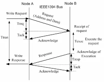
Figure 2-7 present an example of asynchronous write transaction between two nodes. If node A wants to write data into a certain memory area of node B, it sends a write request to node B. Node B acknowledges the receipt of this request. The acknowledgement indicates only the receipt of the request, not yet the execution.
Figure 2-5 Asynchronous Write Request Packet
Figure 2-6 Asynchronous Write Response Packet
Name
Description
Destination_ID The concatenation of the Bus and Node address of the intended node. All ones indicate a broadcast transmission.
TL Transaction Label specified by the requesting node. Only if the response packet contains a correct transaction label, it is possible
to find the corresponding request packet.
RT Retry Code that defines whether this is a retry transaction.
TCODE Transaction Code defines the type of transaction (Read request, Read response, Acknowledgement, etc)
PRI Priority used only in backplane environments
Source_ID Specifies Bus and Node that generated this packet
Destination_offset The address location within the destination node that is being accessed
Packet type Specific Data
Can indicate data length for block reads and writes, or contain actual data for a quadlet write request or quadlet read response.
Header_CRC CRC value for the header part
Optional Data Quadlet aligned data specific to the type of the packet
Optional Data CRC CRC for the Optional Data
Rcode Response Code, specifying the result of this transaction.
Figure 2-7 Asynchronous Transaction between Two Nodes
The timing of asynchronous transmission is shown in Figure 2-7.
(
24) 8
/
400
/
DataSize
bits byte
Treq
Mb s
+
×
=
16
8
/
0.32
400
/
bytes
bits byte
T
resp
s
Mb s
µ
×
=
=
4
8
/
0.08
400
/
bytes
bits byte
T
s
ack
Mb s
µ
×
=
=
4
8
/
0.08
400
/
bytes
bits byte
T
s
ack
Mb s
µ
×
=
=
So the latency during one write transaction is the sum of the time for transferring the request, executing the request and transferring the response. Due to the relatively small value of the time of transferring the response, it can be omitted. Assuming we write data of 4, 56, 2048 bytes payload, the latency will be:
0.88
4
1.92
56
41.76
2048
T
s
Texec
T
s
Texec
T
us
Texec
µ
µ
µ
=
+
=
+
=
+
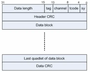
2.4.2 Isochronous Transaction
Figure 2-8 Isochronous Packet
Figure 2-9 gives an example of isochronous transaction between two nodes. Here node A is sending data on isochronous channel N to node B. No acknowledgment or response is generated from Node B. But the maximum sending rate is limited to 125µs, due to the cycled bandwidth allocation on FireWire.
Name
Description
Data Length Data length, can be any value between zero and FFFFh
Tag Isochronous Data format tag
Channel Isochronous Channel Number
Tcode The transaction code for isochronous data block is Ah
Sy Synchronous Code, application specific
Table 2-3 Isochronous Packet Components
As can be seen from above, the protocol overhead in FireWire isochronous packet is 12bytes, i.e. 12 extra bytes needs to be transferred along with the data load. To calculate the protocol efficiency on isochronous transaction, a formula can be deducted:
(
)
100%
(
) 12
DataSize bytes
Eiso
=
DataSize bytes
+
×
The latency for one way isochronous transmission is (assuming the bus speed is 400Mb/s):
(
12) 8
/
400
/
DataSize
bits byte
Tiso
=
+
Mb s
×
So for data payload of 4, 56, and 2048 bytes, the latency will be:
4
56
2048
0.32
1.36
41.2
T
s
T
s
T
s
µ
µ
µ
=
=
Figure 2-9 Example Isochronous Transaction
2.5 Linux FireWire Subsystem
2.5.1 Introduction
In this section, the overview of FireWire subsystem in Linux is presented, and the limitation to use it in real-time context is revealed through basic testing experiments.
2.5.2 System Overview
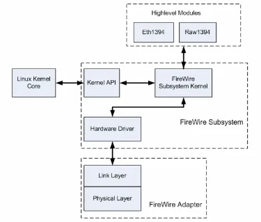
Figure 2-10 Linux FireWire Subsystem Overview
FireWire Subsystem Kernel
More internals of subsystem kernel is revealed in Figure, with explanation following.
Figure 2-11 FireWire Subsystem Kernel
z The Driver Interface block takes care of the management of FireWire adapters (there can be more than one adapter registered to the kernel). Meanwhile it also abstracts out the specifics of various adapter hardware drivers, providing other modules with a common set of services.
z The Transaction Layer Protocol block implements the transaction layer protocol of FireWire.
z The Asynchronous Operation block is responsible for both taking packet send request from applications and dispatching received packets to applications.
to (de)allocate isochronous channel and send packet, as well as for dispatching received packets to applications.
z The Bus Management module is responsible for monitoring the bus status and performing bus management functions as described in 2.3.4.
z The Application Interface module has several functionalities: taking care of the application management, like registering of new application, implementing communication/synchronization between application and kernel and so on. It provides applications with common API that abstracts away from lower level transactions.
FireWire Adapter
The FireWire adapters available in the market are based on one of the following chips:
z aic5800 Adaptec AIC-5800 PCI-IEEE1394
z pcilynx Texas Instruments PCILynx
z Open Host Controller Interface (OHCI1394)
In this project, only adapter of the third type is used, therefore only the corresponding ohci1394 driver is used. See [1394OHCI, 2000] for the specification of OHCI1394.
Highlevel Modules
Highlevel modules in FireWire subsystem are separate functional modules with standardized interfaces connecting to subsystem kernel. Through these interfaces, a certain highlevel module can register itself as being responsible for handling certain events on the bus, e.g. read/write/lock transactions to a certain area of local address space. In another word, the highlevel module can allocate for itself a certain piece of address space on the network.
Here, two highlevel modules are named: eth1394 and raw1394.
Eth1394
Eth1394 stands for Ethernet Emulation over FireWire, all called IPover1394. By using Eth1394, all the applications built on Ethernet network can be directly applied on FireWire, therefore making FireWire a medium alternative for those applications that has been completely developed on Ethernet. See [Johansson, 1999] for IPover1394 protocol specification.
Raw1394
Raw1394 stands for Raw Access over 1394, which is to provide Linux user-space program an interface to directly send and receive packet on FireWire.
2.5.3 Performance Benchmarking on Linux FireWire Subsystem
In [Zhang, 2004], series of experiments were carried out on FireWire, employing Linux user-space programs to measure the latency of transactions on FireWire. But in this project, the Linux kernel in use has been updated to 2.6, which could have new influence on real-time performance. Therefore, new experiments are carried out on Linux FireWire Subsystem system with a 2.6 kernel to study its suitability for use in real-time context.
Test Bench Setup
z PC104:
VIA Eden 600 MHz, 256 Mb Memory, 32 Mb flash disk. z FireWire Adapter:
PC/104+ board with VIA VT6370L Link & Physical layer chip, supporting 400 Mb/s transferring speed at maximum. (See [Zhang, 2004] for more related information) z Software in use: Linux kernel 2.6.12.
Experiment Cases
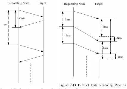
The performance is evaluated in 4 cases: asynchronous transaction without system load, asynchronous transaction with heavy system load, isochronous transaction without system load and isochronous transaction with heavy system load. The experiments on both asynchronous transaction and isochronous transaction are illustrated in Figure 2-18 and Figure. For each case, two nodes are involved in the experiment: one is requesting node that is actively sending the data; another is target node that is passively receiving the data, processing it, and (in asynchronous transaction) send the response back. The data sending rate on client node is 1 KHz. For each case, 100,000 data samples are collected for analyzing. During the experiment, the data load is always 56bytes.
Figure 2-12 Asynchronous Transaction Latency
Figure 2-13 Drift of Data Receiving Rate on Isochronous Transaction
Imposing System Load
The put the experiment in an extremely loaded system, extra processing load needs to be imposed explicitly. Three ways of imposing system load are used together in this experiment. z Creating a flood of interrupts from external world via network by using a third node to
z Creating a flood of interrupts from hardware disk I/O by reading the whole hard disk.
z Creating a flood of system calls via Linux command line. This will make a lot of kernel-user space switch.
Measurement Results
The result is presented by using cumulative percentage curves. At any point on the cumulative percentage curve, the cumulative percentage value (y-value) is the percentage of measurements that had a latency less than or equal to the latency value (x-value). The latency at which the cumulative percentage curve reaches 100 percent represents the worst-case latency measured. For real-time transaction latency, the ideal cumulative percentage curve is one that is steep with a minimal decrease in slope as the curve approaches 100 percent.
Therefore, the cumulative percentage at a certain latency value can be interpreted as the probability of the transaction being able to meet real-time constraints when its deadline is assumed to be equal to that latency value. Since the network in concern will be used in distributed real-time control application, the latency can more or less determines the operating frequency of the system. For example, if the cumulative percentage at latency 100µs is 97%, that mean if the system on the network runs at 10 KHz, only 97% of the distributed data (sensor input, actuator output, etc) can be sent or received on time. The cumulative percentage over ascending latency values are shown in Figure 2-14 and Figure 2-15. The former is for the situation when system is not loaded, while the latter is for the situation when system is heavily loaded. Figure 2-16 and Figure 2-17 present the cumulative percentage over ascending drift values of data receiving rate on isochronous transaction, respectively for the situation of system not being loaded and the situation of system being heavily loaded.
Asynchronous Transaction Latency on Linux FireWire Subsystem
0.00% 20.00% 40.00% 60.00% 80.00% 100.00% 120.00%
0 40 80
120 160 200 240 280 320 360 400 440 480 520 560 600 640 Latency(us)
Cumu
lativePossibility
linux unloaded
Asynchronous Transaction Latency on Linux FireWire Subsystem 0.00% 20.00% 40.00% 60.00% 80.00% 100.00% 120.00% 0
40 80 120 160 200 240 028 320 360 400 440 480 052 560 600 640 680 720 760 800 840 880 920 960
10 00 10 40 10 80 11 20 11 60 12 00 12 40 12 80 13 20 13 60 14 00 14 40 14 80 15 20 15 60 Latency(us) C umu lat ive Pos sib ili ty linux loaded
Figure 2-15 Asynchronous Transaction Latency on Linux FireWire Subsystem when system is loaded
Drift of Data Receiving Rate on Isochronous Transaction using Linux FireWire Subsystem 0.00% 20.00% 40.00% 60.00% 80.00% 100.00% 120.00%
0 20 40 60 80
100 120 140 160 180 200 220 240 260 280 Drift(us)
Cumulative Percentage
linux unloaded
Drift of Da ta Receivin g Rate on Isochronous Transactio n using Lin ux FireWi re Subsyste m
0.00% 20.00% 40.00% 60.00% 80.00% 1 00.00% 1 20.00%
0
50 100 150 200 250 300 350 400 450 500 550 600 650 700 750 800 850 900 950
1
000 1050 1100 1150 Drift(us)
Cumulative P
ercentage
linux loaded
Figure 2-17 Drift of Data Receiving Rate on Isochronous Transaction using Linux FireWire Subsystem when system is loaded
Thereby for hard real-time application, low range of cumulative percentage values does not make any sense (deadline can not be missed that often), so only top of the curve, i.e. at least above 97%, is worth having a closer look, as shown in Figure 2-18 and Figure 2-19.
Drift of Data Dumping Ratio on Isochronous Transaction using RT-FireWire vs Linux RT-FireWire Subsystem
97.00% 97.50% 98.00% 98.50% 99.00% 99.50% 100.00% 100.50% 0 50
100 150 200 250 300 350 400 450 500 550 600 650 700 750 800 850 900 950 1000 1050 1100 1150
Drift(us) Cu mul ati ve Pe rce nta ge
linux unloaded linux loaded
Figure 2-19 Drift of Data Receiving Rate on Isochronous Transaction using Linux FireWire Subsystem
Due to the wide spanning range, the chosen step on the latency value (x-value) is a bit big to make the curve fit in one figure. In Table 2-4 more precise values are presented on three thresholds, i.e. 97%, 99.999% and 100%
Cases 97% threshold 99.999%
threshold
100% (Worst Case)
Asynchronous unloaded 70µs 565µs 580µs
Asynchronous loaded 80µs 1055µs 1475µs
Isochronous unloaded 10µs 175µs 250µs
Isochronous loaded 615µs 1085µs 1090µs
Table 2-4 Threshold Representatives of Real-Time Performance on Linux FireWire Subsystem
Discussion and Conclusion
When the system is not loaded, the experiment results on both asynchronous and isochronous transactions have already shown a relatively big difference in latency values or receiving rate drift in the critical range of cumulative percentage (e.g. between 97% and the worst case (100%) performance). With added load, performance is clearly worsened. Moreover when the system is heavily loaded, the curve is much less steep then in the case system is not heavily loaded. As already discussed, this indicates increased non-determinism and results in poorer real-time properties.
For real-time application, it is the worst case (or almost worst case, like 99.999% threshold) that drives the choice for underlying system. And for normal real-time control application, e.g. motion control, the measured worst case performance can not satisfy the requirements.
3 Real-Time FireWire Subsystem
3.1
Introduction
In this chapter, the implementation of the RT-FireWire (Real-Time FireWire Subsystem) is presented, including the architecture, core components and protocol adaptation.
3.2 Fundamental of RT-FireWire
This section describes the fundamentals of RT-FireWire. In short, the newly designed FireWire subsystem is real-time because the whole software stack is moved to the real-time domain, i.e. RTAI [RTAI 2005]. To unveil more details, the story starts from the explanation about RTAI and its co-existence with Linux. After that, the settling of RT-FireWire in RTAI is described.
RTAI is based on Adeos, which is a resource virtualization layer available as a Linux kernel patch, a simple, yet efficient real-time system enabler, providing a mean to run a regular GNU/Linux environment and a RTOS (e.g. RTAI), side by side on the same hardware. Adeos enables multiple entities called domains to exist simultaneously on the same hardware. These domains do not necessarily see each other, but all of them see Adeos. All domains are likely to compete for processing external events (e.g. interrupts) or internal ones (e.g. traps, exceptions), according to the system-wide priority they have been given [FusionTeam, 2004]. See Figure 3-1 for the illustrated concept. Every domain can register to be notified about certain events. And events are handled in the pipeline way with higher priority domains getting to handle events before lower priority domains.
Figure 3-1 Conceptual Diagram of Domain Pipeline in Adeos
Because RTAI domain is ahead in the pipeline, it is the first to be notified of any incoming interrupts of interest, and because of its heading position, RTAI is totally in control of the interrupt propagation to other low-priority domains, mainly Linux. In other words, RTAI will not let any interrupts go to Linux, if it is busy dealing with some real-time task, e.g. handling a FireWire packet. That way, theoretically RTAI grasps the full control of CPU’s processing power, which is the most critical basis for any real-time subsystem built in it, e.g. RT-FireWire.
therefore all the real-time tasks will have a higher priority than Linux, so all of them can preempt Linux tasks. RT-FireWire employs more than one real-time task in RTAI for its internal processing.
3.3 Settling RT-FireWire in RTAI
This section describes the implementation of settling RT-FireWire in RTAI domain. First the system overview of RT-FireWire is given, based on which the design of task composition for RT-FireWire is presented. Based on the composition, the skeleton of RT-FireWire is built up. Second, the implementation of real-time memory management in RT-FireWire is presented. In the third part of this section, two other relatively minor features in RT-FireWire are introduced: real-time procedure call and packet capturing.
3.3.1 System Overview
Here we present the overview of RT-FireWire in Figure 3-2. Compared with Figure 2-10, the visible changes go to the driver for adapter, kernel implementation and interface to underlying OS, i.e. RTAI.
Figure 3-2 RT-FireWire Overview
Figure 3-3 RT-FireWire Kernel
3.3.2 Architecture and Task Composition
The architecture of RT-FireWire is strictly divided into several layers, each of which corresponds to one layer in the network protocol specification on FireWire. A top-view of the layered architecture is given in Figure 3-4.
Figure 3-4 Layers in RT-FireWire, corresponding to the layers in FireWire protocol
RT-FireWire is composed of several tasks, each of which is a schedulable task object in the RTAI scheduler. All the tasks in RT-FireWire can be seen as servers that handle asynchronous events from outside. The top-view of task composition within RT-FireWire’s layered architecture is shown in Figure 3-5. In next sections, task(s) on each layer will be described.
3.3.3 Hardware Operation Layer
Interrupt Handling
In the hardware operation layer, one task called “Interrupt Broker” is installed to handle the various bus events from external FireWire network. From Object-Oriented point of view, each event is represented by a class inherited from the super-class “ISR Event”, as illustrated in Figure 3-6.
Each event contains the pointer to the routine for handling the event (interrupt from hardware) in concern, and the argument to pass to that routine. So when a certain event is hooked to the broker, the routine addressed by the pointer is executed by the broker.
Short explanation about each event:
z Asynchronous event for request receiving occurs upon arrival of asynchronous request packet.
z Asynchronous event for response receiving occurs upon arrival of asynchronous response packet.
z Asynchronous event for request transmitting occurs after adapter has successfully transmitted a request packet and the acknowledgment has been received from targeting node.
z Asynchronous event for response transmitting occurs after adapter has successfully transmitted a response packet and the acknowledgment has been received from targeting node.
z Besides, there can be 64 events for each isochronous channel if adapter is tuned to listen to that channel.
Figure 3-6 Events in Hardware Operation Layer
Time Stamping in Driver
Figure 3-7 Time Stamping for Incoming and Outgoing Packets
3.3.4 Protocol Processing Layer
Prioritized Request
One limitation while using original FireWire transaction protocol in real-time context is the lack of priority in packets. Because the asynchronous transaction on FireWire consists of request sub-transaction and response sub-transaction, it will make the protocol fit more in real-time context if the request packet comes with a priority that determines how fast the request should be handled on the responding node. Moreover, it would fit more in real-time if the packet that arrived later but with a higher priority can preempt the ongoing processing of previous packet which has a lower priority. This preemptability of transactions, although only limited to the software stack (for now, it is not possible to have preemptive transaction on the Link-Layer of FireWire network), can improve the suitability of using whole FireWire subsystem in real-time context.
Figure 3-8 Prioritized Request
with 0 being defined as the highest. The highest priority is reserved for bus internal server, while the lowest one is reserved for non real-time applications. The rest 14 priorities are for real-time applications.
Prioritized Waiting Queue on Requesting Node
Before sending, the outgoing requests are queued according to the ascending order of their priorities. That way, the real-time requests, even if they are issued later, can still jump over the requests, which are queued before them but with a lower priority. In short, by using this mechanism, the real-time transaction is allowed to preempt the non real-time transaction on the requesting node. This preemption on requesting node is illustrated in Figure 3-9. The number in bracket is the priority.
Figure 3-9 Transaction Preemption on Requesting Node
Brokers for Prioritized Requests on Responding Node
On the responding node, based on the packet priorities, three transaction servers (Request Broker for Bus Internal Service, Request Broker for Real-Time Application and Request Broker for Non Real-Time Application) are employed to handle the requests accordingly, as illustrated in Figure 3-10.
Figure 3-10 Request Brokers in Protocol Processing Layer
Broker for bus internal service has the highest priority among the three. The broker for non real-time application goes to the Linux domain, since it deserves the lowest priority.
3.3.5 Application Layer
In the application layer of RT-FireWire, two tasks are installed for dispatching asynchronous response packets or isochronous packet to applications: asynchronous response broker and isochronous packet broker.
with the request packet; for isochronous transaction, the pointer to the “callback” stays in the settings for that certain channel. The “callback” allows the application to customize the way of synchronization between it and RT-FireWire. In case an immediate synchronization is needed, a semaphore can be used, as illustrated in Figure 3-11.
Figure 3-11 Brokers in Application Layer
3.4 Real-Time Memory Management
Another critical issue in general real-time system is resource allocation. The resource can be memory, hardware I/O, external storage, etc. But in most of the scenarios, memory is the main concern, therefore having a real-time memory allocation is as important as the architecture design. This section addresses the design and implementation of real-time memory management in RT-FireWire.
3.4.1 Common Packet Buffer Structure
To grant the system full extensibility, the static memory allocation in RT-FireWire uses the most generic memory object, so called real-time packet buffer (rtpkb). Rtpkb consists of a buffer management structure and a fixed-sized data buffer. It is used to store network packets on their way from the API routines through the stack to the hardware interface or vice versa. Rtpkb is allocated as one chunk of memory that contains both the management structure (rtpkb header) and the buffer memory itself, as shown in Figure 3-12.
Figure 3-12 Real-Time Packet Buffer
to allow RT-FireWire to freely exchange packet buffer with the applications on it and vice versa.
3.4.2 Packet Buffer Queue
Based on the rtpkb, another component is designed for memory management module, i.e. Packet Buffer Queue. A queue can contain an unlimited number of rtpkbs in an ordered way. An rtpkb can either be added to the head or the tail of a queue. When a rtpkb is removed from a queue, it is always taken from the head.
3.4.3 Packet Buffer Pool
During the initialization of whole system or a certain application, an estimated number of packet buffers must be pre-allocated and kept ready in so-called buffer pools. Most packet producers (e.g. interrupt broker in hardware operation layer, etc) have their own pools in order to be independent of the load situation of other parts of the system. Pools can be extended or shrinked during runtime. Before shutting down the whole system, every pool has to be released.
Pools are organized as normal rtpkb queues. When a rtpkb is allocated, it is actually dequeued from the pool's queue. When freeing an rtpkb, the rtpkb is enqueued to its owning pool. rtpkbs can be exchanged between pools. In this case, the passed rtpkb switches over from its owning pool to a given pool, but only if that pool can pass an empty rtpkb (as for compensation) from its own queue back. This is necessary to keep the memory allocation in each pool clearly independent. This way, the chance for non real-time processing to starve real-time processing for memory is clearly prevented, because each application or processing, either real-time or not, can only hold memory on its own expense, i.e. from its own pool. The buffer exchanging between pools is illustrated in Figure 3-13.
Figure 3-13 Buffer Exchanging between Pools
Figure 3-14 Layered Deployment of Memory Pools in RT-FireWire
3.5 Other Design Issues in RT-FireWire
3.5.1 Real-Time Procedure Call
In RT-FireWire, there is a need to trigger the real-time transaction from non real-time context, i.e. Linux domain. To this end, the Real-Time Procedure Call (RTPC) is designed and implemented. RTPC is an approach to let non real-time task, e.g. task in Linux, run a certain piece of code in real-time context. The rationale behind is illustrated in Figure 3-15.
Figure 3-15 Conceptual Diagram of Real-Time Procedure Call
During system initialization, the “Real-Time Procedure Call Broker” is created in the real-time domain as a real-time task. The request to that broker is sent by tasks in the non real-time domain, possibly user-space task in Linux. The request contains the pointer to the routine that should be run in real-time, the execution arguments and the buffer for storing execution results. The broker handles requests in FIFS (First In First Served) fashion. After finishing a request, it wakes up the corresponding non-real-time task to take back the results.
3.5.2 Real-Time Packet Capturing
Another feature in RT-FireWire is Packet Capturing service. The whole service consists of two parts: packet capturing module in the kernel side and analysis tool in the user side.
The kernel-side module captures both incoming and outgoing packets and put them to a so called “Captured Packet Queue”. The captured packets are passed to analysis tool, which could stay in user space. See Figure 3-16 for the illustration.
Figure 3-16 Working of Packet Capturing
Figure 3-17 Packet Capturing Procedure
3.6 Performance Benchmarking on RT-FireWire
Like what has been done on Linux FireWire Subsystem, a performance benchmarking is also carried out on RT-FireWire to see its suitability for use in real-time.
Test Bench Setup
To make the results directly comparable, the hardware employed in this experiment is exactly the same as in the experiment on Linux FireWire Subsystem.
2 PC104 stacks are employed in this experiment. Detailed information follows:
z PC104:
VIA Eden 600 MHz, 256 Mb Memory, 32 Mb flash disk.
z FireWire Adapter:
PC/104+ board with VIA VT6370L Link & Physical layer chip, supporting 400 Mb/s transferring speed at maximum. (See [Zhang, 2004] for more related information) The software (Operating System) is a bit different, since now it has been a real-time Operating System.
z Software in use: Linux kernel 2.6.12 plus RTAI/fusion 0.9.
Experiment Cases
The performance in 4 cases are evaluated: asynchronous transaction without system load, asynchronous transaction with heavy system load, isochronous transaction without system load and isochronous transaction with heavy system load. The experiments on both asynchronous transaction and isochronous transaction are illustrated in Figure 3-18 and Figure 3-19. For each case, two nodes are involved in the experiment: one is so-called requesting node that is actively sending the request; another is so-called target node that is receiving the requests, processing them, and (in asynchronous transaction) send responses back. The data sending rate on client node is 1 KHz. And the amount of collected samples for each case is 100,000. For each experiment, the data load is set to 56bytes.
Imposing System Load
z Creating a flood of interrupts from external world via network by using a third node to send a lot of random data to the nodes in experiment.
z Creating a flood of interrupts from hardware disk I/O by reading the whole hard disk.
z Creating a flood of system calls via Linux command line. This will make a lot of kernel-user space switch.
Figure 3-18 Asynchronous Transaction Latency
Figure 3-19 Drift of Data Receiving Rate on Isochronous Transaction
3.6.1 Measurement Results
The methodology to present the results of measurements on Linux FireWire Subsystem is reused here. The result is presented by using cumulative percentage curves. At any point on the cumulative percentage curve, the cumulative percentage value (y-value) is the percentage of measurements that had a latency less than or equal to the latency value (x-value). The latency at which the cumulative percentage curve reaches 100 percent represents the worst-case latency measured. For real-time transaction latency, the ideal cumulative percentage curve is one that is steep with a minimal decrease in slope as the curve approaches 100 percent.
Asynchronous Transaction Latency on Real-Time FireWire 0 0.2 0.4 0.6 0.8 1 1.2
50 55 60 65 70 75 80 85 90 95 010 105 110 115 120 125
Latency(us) Cu mu lat i ve Per ce nta ge
56bytes without system load 56bytes with sysem load
Figure 3-20 Asynchronous Transaction Latency using RT-FireWire
Drift of Data Receving Rate on Isochronous Transaction using RT-FireWire 0.00% 20.00% 40.00% 60.00% 80.00% 100.00% 120.00% 0 50 10 0 15 0 20 0 25 0 30 0 35 0 40 0 45 0 50 0 55 0 60 0 65 0 70 0 75 0 80 0 85 0 90 0 95 0 10 00 10 50 11 00 11 50
Drift(us)
Cumulative Percentage
linux unloaded linux loaded
Figure 3-21 Drift of Data Receiving Rate on Isochronous Transaction using RT-FireWire
Cases 97% threshold 99.999% threshold
100% (Worst Case)
Asynchronous unloaded 75µs 90µs 105µs
Asynchronous loaded 90µs 115µs 120µs
Isochronous unloaded 10µs 45µs 50µs
Isochronous loaded 45µs 90µs 95µs
Table 3-1 Threshold Representatives of Real-Time Performance on Linux FireWire Subsystem
The plot on Linux FireWire Subsystem (chapter2) is put together with the one on RT-FireWire in Figure 3-22 and Figure 3-23, which gives more insight about how the performance is improved by RT-FireWire. (Only top of the curves are presented here)
Asynchronous Transaction Latency using RT-FireWire vs Linux FireWire Subsystem
97.00% 97.50% 98.00% 98.50% 99.00% 99.50% 100.00% 100.50%
0 40 80
120 160 200 240 280 320 360 400 440 480 520 560
Latency(us)
Cum
ulative
Possib
ility
linux unloaded linux loaded RT unloaded RT loaded
Drift of Data Receving Rate on Isochronous Transaction using RT-FireWire
97.00% 97.50% 98.00% 98.50% 99.00% 99.50% 100.00% 100.50%
0 50
100 150 200 250 300 350 400 450 500 550 600 650 700 750 800 850 900 950 1000 1050 1100 1150
Drift(us)
Cumulative Percentage
linux unloaded linux loaded RT unloaded RT loaded
Figure 3-23 Comparison between RT-FireWire and Linux FireWire Subsystem (Isochronous Transaction
The data load is another issue that may influence the real-time behavior of RT-FireWire. Figure 3-24 and Figure 3-25 presents the latency or drift over different data load.
Asynchronous Transaction Latency on Real-Time FireWire
0 0.2 0.4 0.6 0.8 1 1.2
50 55 60 65 70 75 80 85 90 95 100 105 110 115 120 125 130
Latency(us)
Cumul
ative Perce
ntage
56bytes without system load 56bytes with sysem load
400bytes without system load 400bytes with system load
Drift of Data Receving Rate on Isochronous Transaction using RT-FireWire
0.00% 20.00% 40.00% 60.00% 80.00% 100.00% 120.00%
0 20 40 60 80
100 120
Drift(us)
Cumulative Percentage
56bytes unloaded 56bytes loaded 400bytes unloaded 400bytes loaded
Figure 3-25 Drift of Data Receiving Rate on Isochronous Transaction using RT-FireWire with different data load
3.6.2 Discussion and Conclusion
Compared with Linux FireWire Subsystem, both asynchronous latency and isochronous drift on RT-FireWire give quite steep curves, as shown in the figures above. That means RT-FireWire gives much more deterministic behavior, which is especially crucial when time critical communication is needed.
But there still exists an un-ignorable gap between the average performance on RT-FireWire and the worst case performance. In case of asynchronous transaction it is the gap between worst case latency and 97% threshold latency value; in case of isochronous transaction it is the worst case data receiving rate drift and 97% threshold drift value. These gaps can not be filled by RT-FireWire due to the limitation of current solution, i.e. RT-FireWire is only software-based solution trying to achieve hard real-time communication. From RT-FireWire point of view, the hardware underlying, even the internal implementation of the Operating System underlying can be kind of “black box”. No attempts are made in this project to open these “black box”.
4 Real-Time IP Network over RT-FireWire
4.1
Introduction
This chapter presents the implementation of stacking real-time IP network in the application layer of RT-FireWire. First, the emulation of Ethernet over FireWire is explained. Second, another Open Source project, RTnet is introduced. RTnet implements a real-time networking framework on Ethernet. Based on the Ethernet emulation, RTnet can be stacked on RT-FireWire. In last part of this chapter, the results of performance measurement on IP over FireWire is given, and compared with the performance of IP over Ethernet.
4.2 Ethernet Emulation over RT-FireWire
4.2.1 “IPover1394” Spec
Before this project, a spec called “IP over 1394” [Johansson, 1999] has been released over Internet, which standardizes the protocol of transferring IP packets on FireWire’s primary transactions, i.e. asynchronous and isochronous, so to make FireWire appear almost the same as Ethernet from the application point of view. In Linux FireWire Subsystem, a highlevel module, Eth1394 (Ethernet Emulation over FireWire), has been developed according to this specification. In this section, the basic rationale behind “IPover1394” is explained at first. After that, the modifications to “IPover1394” are presented and explained which is implemented in the re-implementation of Eth1394 in RT-FireWire.
4.2.2 Minimum Requirements to be IP-capable
Not all serial bus devices/nodes are capable of reception and transmission of IP packets. Several minimum requirements should be fulfilled for a node to be IP-capable:
Nodes have unique hardware address (unique in the network scope). This is important because transaction on the IP level is peer-to-peer. A peer-to-peer relation needs to be established between the IP address and the hardware address of a certain medium.
Nodes support multicasting. This is especially important because the multicasting ARP protocol needs to be carried out for mapping between IP address and the underlying hardware
address.
Besides the above two essential requirements, another desired one is that the underlying medium should support transmitting packets of relatively large data size. This is because IP header introduces some overhead (20 bytes of data). Therefore the medium should at least be able to transmit packets that contain more data than the IP header. Moreover, it is better to have large size packet under IP, since that relatively decreases the protocol overhead.
4.2.3 Addressing Mechanism
The original IPover1394 spec employs the 64-bit GUID (Global Unique ID) of each FireWire adapter chip as the hardware address. The GUID is the ID from manufacturer of each single FireWire adapter, similar to the MAC address of Ethernet adapter. The GUID can be read from the internal register of a certain adapter by using normal asynchronous transaction access on FireWire. That way, the GUID of any FireWire node (adapter) can be known to the whole network, and the peer-to-peer relation between GUID and Node ID can be established.
The strength of using GUID as the hardware address in IP over FireWire is that, the “hardware address” can be guaranteed to be unique even in the world scale, just like the MAC address of Ethernet. But in Ethernet, MAC address is directly used as link layer address for transaction, but in FireWire GUID is not used in transaction. Therefore, any packet that is stamped using GUID must go through an address resolution procedure before it can be put on the fly. Including the address resolution in IP protocol itself, i.e. the resolution between IP address and hardware address (in this case, it is GUID), the whole address resolution procedure includes two sub-resolution, which is not considered being efficient. The conceptual diagram of the address resolution process based on 64-bit GUID is given in Figure 4-1.
Figure 4-1 Addressing Mechanism in “IPover1394” Spec
As stated above, the addressing mechanism in “IPover1394” spec is not considered to be optimal and efficient, especially for real-time context, therefore some modification is needed.
Figure 4-2 Modified Addressing Mechanism in RT-FireWire
To give exactly the same look as normal Ethernet devices, the “MAC” address of Eth1394 is extended to 6-bytes by filling 0 after the 2 bytes FireWire node id, as shown in Figure 4-3. This way all the highlevel stuff that is already working on Ethernet can be directly moved to FireWire, due to the same interface between Ethernet and Eth1394. Figure 4-4 gives the console view of Eth1394 interface on Linux/RTAI.
Figure 4-3 MAC address of Eth1394
Figure 4-4 Console view of Eth1394 interface
4.2.4 Address Resolution Protocol
The address resolution protocol (ARP) is a protocol used by the IP, specifically IPv4, to map IP address to the hardware addresses used by a data link protocol. The protocol operates below the network layer as a part of the interface between the OSI network and OSI link layer.
presented, without referring back to the original one.
The ARP format on Eth1394 and Ethernet are given in Figure 4-5 and Figure 4-6 respectively.
Explanation about some fields:
z Hardware type indicates the underlying medium. E.g. 1 for Ethernet, 24 for FireWire.
z Protocol type indicates the protocol. In case of ARP, it is 0x0080.
z Hw_addr_len is the length of hardware address in bytes. In case of Eth1394, it is 6.
z Lg_addr_len is the length of logical address in bytes. In case of IP, it is 4.
z Operation code indicates the operation type of current packet, 1 for request 2 for response.
z Max_rec indicates the maximum packet size that can be accepted by the sender node.
z Sspd indicates the maximum speed that can be accepted by the sender node.
Figure 4-5 ARP packet format on Eth1394
Figure 4-6 ARP packet format on Ethernet
Because Eth1394 is required to give the exactly same look as normal Ethernet, the 1394ARP packet is converted to a standard ARP packet before it can be delivered to the IP layer, meanwhile, the FireWire layer records down the information that is needed by itself, i.e. max_rec and sspd, see Figure 4-7.
4.2.5 Implementation of Eth1394
This sub-section gives a summary of the implementation of Eth1394. It covers the unicast and broadcast transaction of Eth1394.
Unicast Transaction
The implementation of unicast transaction is based on FireWire’s asynchronous transaction. During the initialization of the interface, a certain piece of address area on the FireWire is allocated. Then a handler (Eth1394_write) is installed to handle all write transactions into that address area (For transactions between Eth1394 modules, only write transaction is used.).
Broadcast Transaction
The implementation of broadcast transaction is based on FireWire’s isochronous transaction. During the initialization of the interface, a certain isochronous channel is allocated. Then a handler (Eth1394_iso) is installed to handle all packets transmitted through that channel.
4.3 Stacking RTnet over RT-FireWire
4.3.1 Introduction about RTnet
RTnet provides a customizable and extensible framework for hard real-time communication over Ethernet. Conceptually similar to RT-FireWire, RTnet also employs static memory management, real-time interrupt handling, non real-time/real-time transaction differentiation to implement a basic real-time stack. The stack overview of RTnet is shown in Figure 4-8. In next section, the application programming interface based on RTnet is presented. For other features of RTnet, one can refer to [RTnet, 2005] and [Kiszka, Zhang et al, 2005]. The latter is attached to this report as appendix.
Figure 4-8 RTnet Stack Overview[Kiszka, Zhang et al 2005]
4.3.2 Application Programming Interface based on RTnet
One important reason to port Eth1394 to RTnet is that, the application programming interface on RTnet can thereby directly be used on FireWire.
I/O interfaces. This socket interface offers UDP and packet sockets for exchanging user data deterministically. Just as RTAI, RTnet permits both the classic kernel mode and more convenient user mode usage (Linux processes) of the interfaces. In this project, applications on RT-FireWire are deployed mainly by using the real-time socket interface via Eth1394 module.
4.3.3 Media Access Control
As important as a real-time-capable stack implementation is a deterministic communication