
Hiroshi Araki
1*, Shingo Kashima
1, Hirotomo Noda
1, Hiroo Kunimori
2, Kouta Chiba
3, Hitomi Mashiko
3,
Hiromasa Kato
3, Toshimichi Otsubo
4, Yoshiaki Matsumoto
5, Seiitsu Tsuruta
6, Kazuyoshi Asari
6, Hideo Hanada
6,
Susumu Yasuda
7, Shin Utsunomiya
1and Hideo Takino
8Abstract
A single aperture and hollow retroreflector [corner-cube mirror (CCM)] that in principle has no internal optical path difference is a key instrument for achieving lunar laser ranging one order or more accurate than the current level (~2 cm). We are developing CCM whose aperture is 20 cm with optimized dihedral angles. The 20-cm CCM yields two times peak height for returned laser pulse compared with Apollo 15’s retroreflector. Two investigations were conducted to confirm the feasibility of the 20-cm aperture CCM. The first is thermo-optical simulation and evalua-tion of the 20-cm CCM in the lunar thermal environment. Through this simulaevalua-tion, it has turned out for the first time that 20-cm aperture CCM made of single-crystal Si or “ultra-low expansion glass–ceramics” such as CCZ-EX® (OHARA Inc.) can be used for CCM with no thermal control, if the perfectly fixed point of CCM is limited to one. The second is annealing and shear loading experiments of single-crystal silicon (Si) samples. Through these experiments, high-tem-perature annealing from 100 to 1000 °C is confirmed to be effective for the enhancement of the adhesive strength between optically contacted surfaces with no optical damage in roughness and accuracy, indicating that this anneal-ing process would enhance the rigidity of CCM fabricated by the optically contacted plates.
Keywords: Lunar laser ranging, Corner-cube mirror, Optical contact, Surface deformation, Fixation, Strehl ratio
© 2016 The Author(s). This article is distributed under the terms of the Creative Commons Attribution 4.0 International License (http://creativecommons.org/licenses/by/4.0/), which permits unrestricted use, distribution, and reproduction in any medium, provided you give appropriate credit to the original author(s) and the source, provide a link to the Creative Commons license, and indicate if changes were made.
Background
LLR and retroreflector on the Moon
Since the first experiment of lunar laser ranging (LLR) in 1969 from McDonald Observatory to Apollo 11 (A11) retroreflector in Mare Tranquilities, LLR has offered unique and invaluable data for nearly half a century. These data have been used as a reference for calculat-ing and establishcalculat-ing numerical or semi-analytical lunar ephemeris. The range accuracy of LLR has been less than 2 cm for the last 20 years owing to the progress of laser transmit/receive system on the ground stations and the
atmospheric signal delay model. Research field related to LLR now covers not only lunar ephemeris but gravi-tational physics, Earth–Moon dynamics, and precision astrometry (Chapront and Francou 2006). Normal points that are statistically corrected range data are more than 20,000 (http://polac.obspm.fr/llrdatae.html), which include unique and important information for investi-gating the deep structure of the Moon (Yoder 1981; Wil-liams et al. 2001, 2013).
However, due to the extreme weakness of LLR signals compared with the satellite laser ranging (SLR), only five observatories have succeeded in LLR by now, that is, McDonald, Haleakala, Matera, Côte d’Azur, and Apache Point, and more than 75 % of LLR signals are from the largest retroreflector at the Apollo 15 site (A15) (http:// *Correspondence: [email protected]
1 National Astronomical Observatory of Japan (NAOJ), 2-21-1 Osawa,
Mitaka, Tokyo 181-8588, Japan
ilrs.gsfc.nasa.gov/science/scienceContributions/lunar. html). Therefore, especially for the investigation of the lunar rotational variations, increasing normal point data from retroreflectors as far as possible from the A15 site (Turyshev et al. 2013) is an important goal, in addition to the goal of increasing the range accuracy. Further, it is reported that the reflectivity of lunar reflectors shows degradation by a factor of 10 or more (Murphy et al. 2010), which may affect data accuracy and productivity. To resolve these problems, it is necessary to deploy a new retroreflector whose “reflection performance” (hereafter, we define it as the peak height of received laser pulse over the unit laser output energy with a specified time width) is greater than that of the A15 retroreflector on the lunar southern hemisphere, for example, from the middle to high latitude or lunar peripheral region. In the next sec-tion, we describe the 20-cm aperture and hollow-type corner cube as such a new retroreflector model.
Conceptual design of new retroreflector
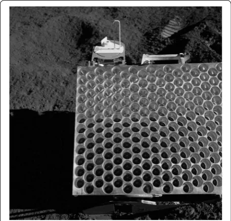
To yield more reflection performance than A15’s ret-roreflector composed of 300 corner-cube prisms with an aperture of 38 mm, more abundant unit corner-cube prisms must be arrayed. Of course, it is difficult to achieve this, because the size and weight of such an array type retroreflector will surpass the A15 model (Fig. 1). As for the reflection performance, the ray path differ-ence in the A15 retroreflector is already ±7 cm [±1 (m) sin 8.2°] due to the array configuration and the optical (lunar orbital) libration, which is the main factor that
limits range accuracy and peak value of returned pulse through the broadening of output laser pulse (Turyshev et al. 2013). “Single-element retroreflector” (SERR) com-posed of a single corner-cube reflector made of a prism or three mirrors, which has no optical path difference in principle, is considered a solution to overcome these problems. The performance of SERR is determined in principle only by the aperture area. The larger aperture can receive larger signals that allow more precise rang-ing. There is a detailed report on SERR for LLR (Otsubo et al. 2011), which concludes that SERR whose aperture is 20 cm yields two times reflection performance com-pared with the A15 retroreflector if a small offset angle [dihedral angle offset (DAO)] being 0.65 ± 0.1 arc second (corresponding to 0.44 ± 0.068 μm offset at the edge of 20-cm SERR) is added to one of three dihedral angles of the SERR. Therefore, we investigate 20-cm aperture SERR hereafter. The aperture diameter of the prism-type SERR is practically limited by the uniformity and thermal property of the prism material as described below; how-ever, the hollow-type SERR is free from such a limitation if the problems relating to deployment and/or environ-mental problems are solved.
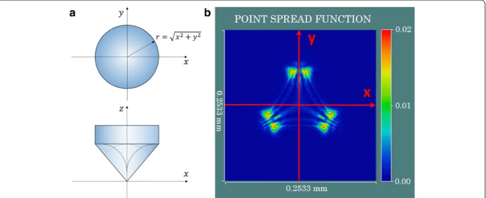
All existing lunar retroreflectors consisting of arrayed corner-cube prisms are more suitable for space use than hollow-type reflectors in terms of stiffness and stability. Recently, a 10-cm aperture corner-cube prism was devel-oped for LLR (Currie et al. 2011); however, it is consid-ered for the 20-cm aperture that inhomogeneity and/or temperature dependency of the refractive index of the prism may cause severe optical degradation in addition to weight and size problems. The optical performance of the 20-cm aperture corner-cube prism made of synthetic quartz is simulated using an evaluation model taking into account the inhomogeneity of prism’s refractive index (n) as follows: ∆n (r, z)/n = 3 × 10⁻⁶ (z/68)2 (r/127.5)2, where z (mm) and r (mm) are defined in the cylindrical coordinates (Fig. 2a) and ∆n is the variation of “n” of the highest grade synthetic quartz (personal communications with Shin-Etsu Chemical Co., Ltd.). Unfortunately, even on this condition, the 20-cm aperture corner-cube prism shows a severely distorted focal image whose Strehl ratio is 0.02, indicating a poor optical performance (Fig. 2b), where the Strehl ratio is defined as the ratio of focal image peak intensity of the point source between real and perfect optics. Therefore, it is difficult to use the corner-cube prism whose aperture diameter is 20 cm or more as SERR for LLR if we take further the effect of temperature dependence of “n” into account. Thus, we focus on the hollow-type SERR hereafter.
In summary, the following three characteristics required for a new generation LLR retroreflector are derived: (1) SERR, (2) 20 cm aperture with DAO, and
(3) hollow type. We call the retroreflector being (1) SERR and (3) hollow type as corner-cube mirror (CCM). The deployment of CCM whose aperture is 20 cm on the lunar near side and far from A15 would contribute greatly to the investigation of the lunar precise rotation.
Methods
Two investigations were conducted to confirm the fea-sibility of the 20-cm aperture CCM as follows, and their results and implications are described from the next section:
[I] Thermo-optical simulation and evaluation of 20-cm aperture CCM in the lunar thermal environment: First, two candidate materials for CCM are sought for higher thermal diffusivity, lower thermal expansion, and higher specific stiffness. Then, surface tempera-ture, deformation, and optical qualities of CCM are simulated using mathematical models of CCM made of the selected materials. Software is Thermal Desktop®, ANSYS®12, and CodeV10.6SR1 for temperature, defor-mation, and optical simulation, respectively.
[II] Annealing and shear loading experiments of the candidate material, single-crystal silicon (Si): The pur-pose of these experiments is to confirm whether the annealing may be introduced as post-processing of the optical contact for the CCM fabrication. The opti-cal contact technique is to adhere two surfaces stiffly without using adhesive by contacting and pressing two polished surfaces whose roughness is less than about 1 nm level (Ra). This is suitable for the CCM used in
space without any degassing and contamination from adhesive. Five small Si plates are heated individually to 100, 400, 600, 800, and 1000 °C. Then, the surface accuracy and roughness of these plates are measured and their measurements compared with the pre-annealing measurement data. The optically contacted Si samples were also heated from 100 °C to 1000 °C, and then shear loading was applied to these samples to confirm that the adhesive strength of the optically contacted surface may increase in accordance with temperature as described by Shimbo et al. (1986).
Results and discussion
Material of CCM
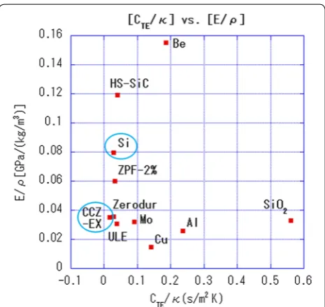
CCM on the Moon is exposed to a severe thermal envi-ronment with an extremely wide temperature range of about 100 to 400 K (Vasavada et al. 2012). The main concern for this situation is that shadow of CCM cast on itself in the daytime may cause temperature varia-tion and deformavaria-tion of the CCM surface, leading to the degradation of the optical performance. Thus, it is neces-sary for the CCM material to have a small coefficient of thermal expansion (CTE) and a large thermal diffusivity (κ) to reduce CCM degradation. |CTE/κ| and E/ρ (Young’s modulus E/density ρ) of candidate materials for CCM are plotted in Fig. 3. We selected CLEARCERAM™-Z EX (OHARA Inc.; hereafter CCZ-EX®) and single-crystal silicon (Si) as an example of ultra-low expansion glass ceramics and other type material, respectively, but not select HS-SiC even with low |CTE/κ| and very high E/ρ because its surface is difficult to polish to the level
where the optical contact technique can be used for the fabrication of CCM. In the next section, simulations are used to examine thermal deformation and optical perfor-mance of CCM made of these two materials when they are deployed on the lunar surface in daytime.
Optical performance of CCM on the Moon
We examine the optical performance of CCM made of Si or CCZ-EX® in the lunar thermal environment by the numerical simulation. First, the temperature on the CCM surface is calculated using mathematical model of the whole retroreflector system including CCM (“tempera-ture of CCM surface”). Second, deformation of the CCM surface is calculated based on derived temperature dis-tribution (“deformation of CCM surface”). And third, the optical performance is calculated on the CCM surface deformation (“optical degradation of CCM”).
Temperature of CCM surface
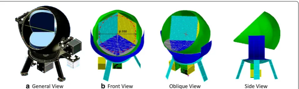
Thermal Desktop® software is employed for the calcula-tion of CCM temperature. The mathematical model of the whole reflector system is made of the CCM itself, hemi-spherical sunshade, supporting frame, tripod, and other parts (Fig. 4). The driver system for turning CCM toward the Earth, which is attached to the back of the tripod, is not taken into account as a heat source for the thermal
calculation, because it is not used during LLR opera-tion. CCM materials are Si or CCZ-EX® as described in chapter “Material of CCM.” The shape of the CCM aper-ture is hexagonal with 141.42 mm length on one side, and thus, the diameter of its inscribed circle is 200 mm. The numerical solid model of CCM for the Thermal Desktop® is gridded to 20 × 20 × 2 nodes to match the scheme of ANSYS®12 software for the subsequent calculation of CCM deformation, where the temperature profile inside the CCM plates (10 mm thickness) is taken into account for accurate calculation. Thermal properties and densities of Si and CCZ-EX® used for the calculation are given in Table 1. Thermal conductivity and specific heat of Si are at 80 °C based on Glassbrenner and Slack (1964), and those of CCZ-EX® are averaged measurements from −150 to
+100 °C by AGNE Gijutsu Center Inc. The mirror coat-ing that is the thermal boundary of CCM surface to space is supposed to be silver (Ag; absorption coefficient
α = 0.04, emissivity ε = 0.02) or aluminum (Al; absorp-tion coefficient α = 0.25, emissivity ε = 0.04). Other parts are supposed to be made of carbon fiber-reinforced plas-tics (CFRP; absorption coefficient α = 0.8, emissivity
ε = 0.89). Thickness of the hemispherical sunshade, sup-porting frame, and tripod is 5 mm. Radiative thermal cou-pling of CCM with lunar surface (albedo 0.07) and space, and conductive thermal coupling are taken into account between “CCM and sunshield,” “sunshield and support-ing frame,” and “tripod and lunar surface” as 0.04 W/K, 0.005 W/K × 2, and 0.045 W/K × 3, respectively.
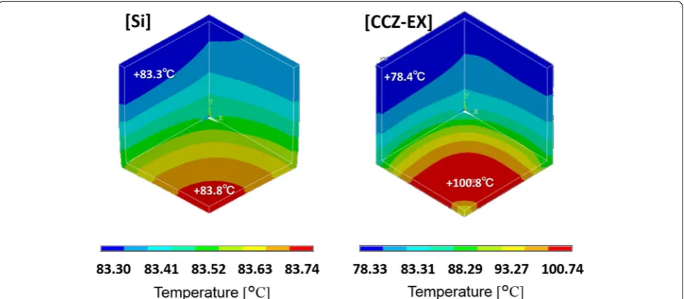
Surface temperature on the CCM that is set inside Tycho crater (11.2°W, 43.3°S) is calculated, where its optical axis is aligned in the direction of Earth, and self-shadow casting on CCM is taken into account. Heating by solar radiation and lunar reflective radiation is also taken into account assuming that solar radiation con-stant is 1421 W/m2, but radiative heating by the Earth is ignored. Lunar surface temperature profile ranging from about 85 to 365 K at Apollo 17 site (A17; [30° 44′58.3 E, 20° 09′ 50.5 N]) is used for the calculation (Keihm and Langseth 1973). Thus, we should take note that calcu-lated CCM temperature and eventually its deformation shown below are somewhat overestimated because the ground temperature at A17 is higher than at Tycho crater due to the lower latitude of A17 than that of Tycho cra-ter. Results of temperature calculation are summarized in Table 2, and temperature maps on CCM made of Si and CCZ-EX® coated by silver are shown in Fig. 5. Tempera-ture variance becomes much larger for aluminum coating than silver because absorption α of aluminum is larger than silver, indicating that aluminum coating causes larger deformation of CCM surface than silver coating. Therefore, we take silver as the coating material from the next section.
Fig. 3|CTE/κ| versus (E/ρ) map of several candidate materials for
Deformation of CCM surface
Deformation of the CCM under the temperature distri-bution obtained in the previous section is calculated by ANSYS® 12 with the 20 × 20 × 2 mesh numerical model used for the temperature calculation assuming that the surface is perfectly flat when the CCM temperature is 25 °C. Thermal expansion data (CTE) of Si and CCZ-EX® necessary for the calculation are shown in Fig. 6a, b, respectively.
Deformation of CCM surface under the temperature distribution obtained in the previous section is calcu-lated by ANSYS® 12 with 20 × 20 mesh and with the assumption that the surface is perfectly flat when CCM temperature is 25 °C. Thermal expansion data (CTE) of
single-crystal Si and CCZ-EX® necessary for the calcula-tion are shown in Fig. 8a, b, respectively.
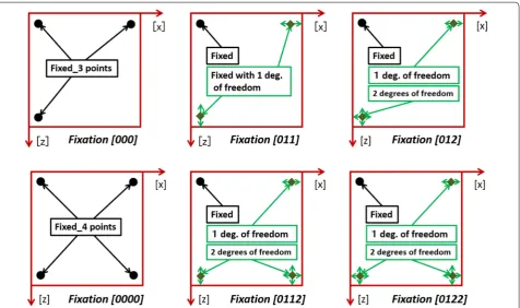
It is anticipated that calculation results may be highly dependent on the way CCM is mounted on the struc-ture (Fig. 4b). Hereafter, we suppose six fixing methods of CCM, that is, [000], [011], [012], [0000], [0112], and [0122], where the former three stand for “three-point fixing” and latter three “four-point fixing,” respectively (Fig. 7). The calculation is performed for two materials (Si and CCZ-EX®) and six fixing methods above, that is, for 12 cases in total, where fixed points are the backside of CCM. Density, Young’s modulus, and Poisson’s ratio of the two materials are given in Table 3, where anisotropy of the elastic properties of Si is taken into account (Wort-man and Evans 1965).
Four deformation maps calculated by ANSYS® 12 are shown in Fig. 8 for the case of Si_[000], CCZ-EX®_[000], Si_[011], and CCZ-EX®_[011], where, for example, Si_[000] means that CCM material is Si and the fixing method is [000]. Normal component of surface deforma-tion for the case of Si_[000] is 40 μm at most being more than two orders of magnitude larger value than 78 nm for Si_[011]. Similarly, for the case of CCZ-EX®_[000], the deformation is 1 μm at most being four times larger than 250 nm for CCZ-EX®_[011].
Maximum normal components of surface deformation for all 12 cases are summarized in Table 4. It is clearly shown that perfect multi-point fixation such as [000] or [0000] causes huge surface deformation.
Optical degradation of CCM surface
The optical performance of CCM is evaluated by the cal-culation of the point spread functions (PSF) and Strehl ratio by CodeV10.6SR1 software. Strehl ratio is consid-ered here to be the ratio of intensity peak of focal image by deformed CCM over the intensity peak value of per-fect image by the deformation free CCM. PSF maps are
Fig. 4 a General view of the whole reflector model. b Mathematical model of the whole reflector system used for the calculation of temperature on CCM surface by Thermal Desktop® software. See text for more explanation
Table 1 Thermal conductivity, specific heat, and density used for the temperature calculation of CCM made of Si and CCZ-EX®
Material Thermal conductivity
(W/m/K) Specific heat (J/kg/K) Density (kg/m3)
Si 125.34 760 2329
CCZ-EX® 1.10 693 2550
Table 2 Results of maximum/minimum surface tempera-ture and their differences on CCM made of Si or CCZ-EX®
coated by silver (Ag) or aluminum (Al)
CCM surface coated by aluminum shows much larger temperature difference than the surface by silver coating due to large absorption α
Material Coating Maximum
shown in Fig. 9 for the same cases as Fig. 8, revealing that CCM made of both candidate material (Si or CCZ-EX®) fixed perfectly to the structure on multi-points
cannot be used at all for LLR because the optical perfor-mance is severely degraded due to the huge deformation of CCM surface. However, when only one point is fixed perfectly and other fixed points have one or two degrees of freedom along the CCM surface, the optical degrada-tion is very small, indicating no problem for LLR use. Strehl ratios are summarized in Table 5, indicating again that perfect fixing on multi-points leads to severe opti-cal degradation of CCM. For the cases other than perfect
multi-point fixation, Strehl ratio is confirmed to be more than about 90 %, and thus there is no optical problem for LLR use.
Optical performance of CCM expected on the Moon
CCM made of Si or CCZ-EX®, deployed inside Tycho
crater in the daytime, is heated up to 83.3–83.8 °C or 78.3–100.7 °C, respectively (Fig. 5). The temperature difference within a CCM made of CCZ-EX® is 22.4 °C
being much larger than that of CCM made of Si (0.5 °C). However, the deformations of CCM made of Si and CCZ-EX® are comparable, unless the multi-point fixation is Fig. 5 Temperature distribution on the surface of CCM made of Si or CCZ-EX® with silver coating. Temperature variation is 0.5 degrees for CCM made of Si, whereas it is 22.4° for that made of CCZ-EX®
employed. Actually, for the fixation other than [000] or [0000], maximum normal deformation is 78 or 91 nm for CCM made of Si and 106 or 251 nm for CCM made of CCZ-EX®, respectively (Table 4). This is because |C
TE| of Si is much larger than that of CCZ-EX® contrary to
the temperature difference between these two materials. Strehl ratios also show good values from 89.7 to 99.3 % for the cases other than [000] or [0000]. Thus, CCM made of these two materials suffers no optical damage unless perfect multi-point fixation ([000] or [0000]) is employed (Table 5). Therefore, if the perfectly fixed point of CCM is
limited to one, CCM made of Si or CCZ-EX® can be used safely for LLR with no thermal control.
As for the perfect multi-point fixation ([000] or [0000]), normal deformation reaches 40–46 μm for CCM made of Si or 0.93–0.99 μm for that made of CCZ-EX®, respec-tively, where large thermal deformation occurs due to multi-point fixation of the CCM even when slight temper-ature difference to the reference (25 °C) is applied, which leads to poor Strehl ratios from 4.4 to 7.3 %. Therefore, it is difficult to use CCM being fixed on multi-points for LLR.
However, CCM made of CCZ-EX® shows smaller nor-mal deformation than Si even for the multi-point fixa-tion due to the very small |CTE|. For example, the normal deformation of CCM made by CCZ-EX® for [000] fixa-tion is 0.99 μm, which is only about four times larger than the case for [011] fixation (normal deformation is 0.25 μm and the Strehl ratio is 91 %) (Tables 4, 5). There-fore, it may be possible to employ the multi-point fixation method for CCM support if we can use material whose |CTE| is less than 1/4 of CCZ-EX® and thermal diffusivity is the same as CCZ-EX® in future.
In summary, two conclusions are derived on the per-formance of CCM as follows:
Fig. 7 Six fixation methods of CCM to the holder. The red square of each figure represents the backside of CCM base. CCM deformation is calculated for all these fixation methods and two materials (Si and CCZ-EX®), thus 12 cases in total. The names for fixation are attached under each figure. For example, [000] means that three points are fixed perfectly and [012] means that degree of freedom of motion is zero (perfectly fixed), one (motion along one direction other than [z] is allowed), and two (motion within the CCM surface is allowed)
Table 3 Density, Young’s modulus, and Poisson’s ratio of Si and CCZ-EX® used for the calculation of CCM deformation.
Originated from Wortman and Evans (1965)
Data for Si are cited from the Web resource (http://www.ioffe.ru/SVA/NSM/ Semicond/Si/mechanic.html#Basic)
Material Density (kg/m3) Young’s modulus (GPa) Poisson’s ratio
Si 2329 185 (111)
170 (110) 130 (100)
0.28 (100) 0.26 (111)
1. Thermal deformation and optical performance of CCM whose aperture is 20 cm are strongly depend-ent on the fixation method. CCM made of Si and CCZ-EX® can be used for LLR retroreflector with no thermal control on the Moon if the perfectly fixed point of CCM is limited to one.
2. However, it may be possible to introduce the multi-point fixation method for CCM support if in future we can use CCM material whose |CTE| and κ are less than 1/4 of CCZ-EX® and the same as CCZ-EX®, respectively.
Annealing and shear loading experiment of Si test pieces
We investigated whether the optical contact technique with a high-temperature annealing process can be applied to CCM fabrication by conducting experiments with Si test pieces, aiming to solve two problems: (I) how much CCM surface degrades optically by high-tempera-ture annealing and (II) how much improvement of stiff-ness between optically contacted interface is expected by the annealing process (Noda et al. 2015).
Experiments I and II are conducted corresponding to the above problems (I) and (II), respectively: [Experi-ment I] Mirror-polished Si plates (<1 nm in RMS surface roughness; 20 mm × 21 mm × 5 mm) were prepared. Before the annealing test, the surface accuracy and roughness were measured using a laser interferom-eter (ZYGO, GPI XP) and an atomic force microscope (AFM). The same measurements were conducted after the annealing process for comparison. One thing should be noted that the area measured with AFM is 1 micron by 1 micron for each sample, while the position accuracy of AFM is only about 1 mm. Therefore, it is not the case that the same region was measured before and after the annealing. [Experiment II] Five sets of test pieces made of optically contacted three Si plates with the same dimen-sion were prepared (Fig. 10) for the shear loading test so that the center piece could be pushed using a pressurizer (Autograph AG-1, SHIMADZU Corp.) to generate shear stress on both of the optically contacted interfaces.
Five small plates for [Experiment I] and five test pieces for [Experiment II] had been pre-heated to 100 °C during
Fig. 8 Deformation maps of CCM for the fixation [000], [011] and two materials (Si and CCZ-EX®). Normal component of surface deformation is very large when multi-points are fixed perfectly
Table 4 Maximum normal deformation of CCM surface for two materials (Si and CCZ-EX®) and six fixation methods
(Fig. 7)
Fix_3 and 4 stand for “three-point fixing” and “four-point fixing,” respectively
Material Fix_3 [000] [011] [012] Fix_4 [0000] [0112] [0122]
Si (μm) 40.17 0.0780 0.0905 46.22 0.7910 0.0909
the optical contact process. They are heated again and annealed for two hours up to 100, 400, 600, 800, and 1000 °C, in the electric furnace, respectively, and then naturally cooled down to the room temperature within half a day or a day. The shear loading test in [Experiment II] was carried out in a box, one side of which is made of transparent acrylic for observation and to prevent test pieces from scattering fragments when ruptured.
Results of [Experiment I] and [Experiment II] are given in Tables 6 and 7, respectively. From [Experiment I], the
degradation of surface accuracy is found to be less than 0.003 λHeNe (RMS; λHeNe = 633 nm) that is small enough to be ignored. The degradation of surface roughness is also slight enough to be ignored being less than 0.1 nm (Ra) that is equivalent to the optical scattering loss less than 6 × 10⁻⁵ TIS (total integrated scattering), where
TIS=(4π σ/532) 2
in which σ is surface roughness and λ532 is wavelength (532 nm). These results suggest that the surface accuracy and roughness of a mirror made of Si show no degradation even in high-temperature
Fig. 9 Point spread functions of CCM for the fixation [000], [011] and two materials (Si and CCZ-EX®). If perfectly fixed point of CCM is limited to one, optical performance shows little degradation with Strehl ratio more than 90 %
Table 5 Strehl ratios of CCM surface for two materials (CCZ-EX® or Si) and six fixation methods (Fig. 7)
Fix_3 and 4 stand for “three-point fixing” and “four-point fixing,” respectively
Material Fix_3 [000] [011] [012] Fix_4 [0000] [0112] [0122]
Si 0.044 0.993 0.908 0.061 0.992 0.947
environments up to 1000 °C. [Experiment II] shows that the rupture strength of a test piece generally increases with the maximum temperature exposed during the annealing process and that the adhesive strength of the test piece annealed at 1000 °C is several times larger than that annealed at 100 °C, where “rupture strength” of the piece at 1000 °C is not at ruptured timing but the maxi-mum value during the pushing operation because the test piece was not ruptured during the test (Table 7).
In summary, an additional annealing process up to 1000 °C on the optically contacted CCM element plates is confirmed to enhance the adhesive strength several times without any damage of the optical performance. This annealing process prior to the coating would be a great contribution for the fabrication of CCM.
Conclusion and future prospects
A 20-cm CCM whose reflection performance is twice that of the Apollo 15 reflector on the Moon will bring a breakthrough to LLR and lunar and planetary geodesy through significant improvements in range accuracy, data productivity, and the expansion of the ground station network. In this paper, we have confirmed for the first time that a 20-cm hollow-type SERR (20-cm CCM) can be used for LLR retroreflector in the lunar thermal envi-ronment. In addition, we found that the optical contact with high-temperature annealing is effective to enhance the rigidity of CCM.
We have investigated a 20-cm aperture CCM by the thermo-optical simulation. First, a 20-cm SERR made of a corner-cube prism is confirmed to be difficult to use as a lunar retroreflector due to the limit of the mate-rial uniformity and/or thermal variation of the refrac-tive index. Then, two important conclusions are derived from our simulation: The first is that a 20-cm aperture CCM made of “single-crystal silicon (Si)” or “ultra-low expansion glass–ceramics” such as CCZ-EX® (OHARA
Inc.) can be used as a lunar retroreflector with no ther-mal control if the perfectly fixed point of CCM is limited to one; the second is that it may be possible to introduce the multi-point fixation method for CCM support if in future we can use CCM material whose |CTE| and κ are less than 1/4 of CCZ-EX® and the same as CCZ-EX®,
respectively.
Next, we have conducted annealing experiments from 100 to 1000 °C and shear loading experiments of Si sam-ples and confirmed the efficiency of high-temperature annealing for the enhancement of the adhesive strength between optically contacted surfaces with no optical damage in roughness and accuracy. This annealing pro-cess would enhance the rigidity of CCM made of the optically contacted plates.
The remaining important issues on the CCM design are as follows: (1) to search for a tougher coating mate-rial than silver with similar thermal properties and reflectivity, (2) to investigate the radioactive affection on the reflectivity and/or deformation of the surface of the
Fig. 10 Test piece for the assessment of optical contact bond-ing force (left). The dimension of each component plate is 20 mm × 21 mm × 5 mm, and three plates are optically in contact with each other. The middle plate is vertically shifted so that forces can be applied to this plate to generate shear stress on both of the opti-cally contacted interfaces (right)
Table 6 Results of [Experiment I]
Surface accuracy and roughness measurements of Si plates. RMS stands for root mean square, and Ra stands for the arithmetic average of absolute topographic height
Temperature (°C) Surface accuracy ZYGO interferometer [RMS
Table 7 Results of [Experiment II]
or SiO2 (SiOx) coating over the silver one is expected to have more resistivity against the space radiative environ-ment and also has a function to protect the silver coat-ing from the corrosion on the ground, but the long-term resistivity is future issue to be confirmed. (3) is an impor-tant issue for the quantitative analysis of return signals of LLR. As for (4) and (5), 20-cm aperture CCM must have DAO being 0.65 ± 0.1 arc second, which requires figur-ing precision better than several tens of nanometer level. To find and establish how to add DAO on the CCM, we are now investigating the performance and applicabil-ity of ion beam figuring (IBF) to our purpose (Allen and Romig 1990; Schindler et al. 2001).
Abbreviations
AFM: atomic force microscope; CCM: corner-cube mirror; CCZ-EX®: CLEARCERAM™-Z EX; CFRP: carbon fiber-reinforced plastics; CTE: thermal
expansion coefficient; DAO: dihedral angle offset; HS-SiC: high-strength reaction-sintered SiC; IBF: ion beam figuring; ILRS: International Laser Ranging Service; LLR: lunar laser ranging; SERR: single-element retroreflector; TIS: total integrated scattering; ULE: ultra-low expansion glass; ZPF: zero expansion stiffness ceramics.
Authors’ contributions
HA selected candidate materials for CCM, performed optical evaluation of the CCM mathematical model and other optical analyses with SK, conducted the annealing and shear loading experiment of Si test pieces, analyzed data obtained by the experiments, and prepared the manuscript. SK performed optical evaluation of the CCM mathematical model and other optical analyses, conducted the annealing and shear loading experiment of Si test pieces, and contributed a design of CCM configuration. YM calculated surface tempera-ture of CCM model. KC, MH, and HK calculated surface deformation of CCM model. SU and HA measured the coefficient of thermal expansion of CCZ-EX®. SU, SY, ST, and KA contributed the annealing and shear loading experiment of Si test pieces. HN, HH, and HT joined and contributed to the discussion. All authors read and approved the final manuscript.
Author details
1 National Astronomical Observatory of Japan (NAOJ), 2-21-1 Osawa, Mitaka,
Tokyo 181-8588, Japan. 2 National Institute of Information and
Communica-tions Technology (NICT), 4-2-1 Nukui-Kitamachi, Koganei, Tokyo 184-8795, Japan. 3 Faculty of Engineering, Iwate University, 3-18-8 Ueda, Morioka, Iwate
020-8550, Japan. 4 Graduate School of Social Sciences, Hitotsubashi University,
2-1 Naka, Kunitachi, Tokyo 186-8601, Japan. 5 PLANET Inc., Light Bldg. 7F,
2-12-3 Ginza, Chuo-ku, Tokyo 104-0061, Japan. 6 National Astronomical
Observatory of Japan (NAOJ), 2-12 Hoshigaoka-cho, Ohshu, Iwate 023-0861, Japan. 7 Japan Aerospace Exploration Agency (JAXA), 2-1-1 Sengen, Tsukuba,
Ibaraki 305-8505, Japan. 8 Faculty of Engineering, Chiba Institute of
Technol-ogy, 2-17-1 Tsudanuma, Narashino, Chiba 275-0016, Japan.
Received: 7 January 2016 Accepted: 18 May 2016
References
Allen LN, Romig HW (1990) Demonstration of an ion-figuring process. In: Advanced optical manufacturing and testing, 22, SPIE 1333:22–33. doi:10.1117/12.22786
Chapront J, Francou G (2006) Lunar laser ranging: measurements, analysis, and contribution to the reference Systems. IERS Tech Note 34:97–116 Currie DG, Dell’Agnello S, Delle Monache GO (2011) A lunar laser ranging
retroreflector for the 21st Century. Acta Astronaut 68(7–8):667–680. doi:10.1016/j.actaastro.2010.09.001
Glassbrenner CJ, Slack GA (1964) Thermal conductivity of silicon and germanium from 3 K to the melting point. Phys Rev 134(4):1058–1069. doi:10.1103/PhysRev.134.A1058
Keihm SJ, Langseth MG Jr (1973) Surface brightness temperatures at the Apollo 17 heat flow site: thermal conductivity of the upper 15 cm of regolith. Geochim Cosmochim Acta Suppl 4(3):2503–2513
Murphy TW Jr, Adelberger EG, Battat JBR, Hoyle CD, McMillan RJ, Michelsen EL, Samad R, Stubbs CW, Swanson HE (2010) Long-term degrada-tion of optical devices on the moon. Icarus 208:31–35. doi:10.1016/j. icarus.2010.02.015
Noda H, Araki H, Kashima S, Utsunomiya S, Tsuruta S, Asari K, Yasuda S (2015) Thermal tolerance test for the development of a hollow ret-roreflector for future lunar laser ranging. Paper presented at the 46th Lunar and Planetary Science Conference, The Woodlands Texas, 16-20 March 2015
Otsubo T, Kunimori H, Noda H, Hanada H, Araki H, Katayama M (2011) Asym-metric dihedral angle offsets for large-size lunar laser ranging retroreflec-tors. Earth Planets Space 63: e13-e16. doi:10.5047/eps.2011.11.001 Schindler A, Haensel T, Flamm Di, Frank W, Boehm G, Frost F, Fechner R, Bigl
F, and Rauschenbach B (2001) Ion beam and plasma jet etching for optical component fabrication. In: Lithographic and Micromachining Techniques for Optical Component Fabrication, 217, SPIE 4440:217-227. doi:10.1117/12.448043
Shimbo M, Furukawa K, Fukuda K, Tanzawa K (1986) Silicon-to-silicon direct bonding method. J Appl Phys 60:2987–2989. doi:10.1063/1.337750 Si—Silicon; Mechanical properties, elastic constants, lattice vibrations. http://
www.ioffe.ru/SVA/NSM/Semicond/Si/mechanic.html#Basic. Accessed on 3 May 2016
Suyama S, Kameda T, Itoh Y (2003) Development of high-strength reaction-sin-tered silicon carbide. Diam Relat Mater 12(3–7):1201–1204. doi:10.1016/ S0925-9635(03)00066-9
Turyshev SG, Williams JG, Folkner WM, Gutt GM, Baran RT, Hein RC, Somaward-hana RP, Lipa JA, Wang S (2013) Corner-cube retro-reflector instrument for advanced lunar laser ranging. Exp Astron 36(1):105–135. doi:10.1007/ s10686-012-9324-z
White GK, Minges ML (1997) Thermophysical properties of some key solids: an update. Int J Thermophys 18(5):1269–1327. doi:10.1007/BF02575261 Williams JG, Boggs DH, Yoder CF, Ratcliff JT, Dickey JO (2001) Lunar rotational
dissipation in solid body and molten core. J Geophys Res 106:27933– 27968. doi:10.1029/2000JE001396
Williams JG, Boggs DH, Folkner WM (2013) DE430 lunar orbit, physical librations and surface coordinates. In: NAIF planetary data system navigation node, NASA. http://naif.jpl.nasa.gov/pub/naif/generic_ kernels/spk/planets/de430_moon_coord.pdf. Accessed on 3rd May, 2016
Wortman JJ, Evans RA (1965) Young’s modulus, Shear modulus, and Poisson’s ratio in silicon and germanium. J Appl Phys 36:153–156. doi:10.1063/1.1713863

![Fig. 9 Point spread functions of CCM for the fixation [000], [011] and two materials (Si and CCZ-EX®)](https://thumb-us.123doks.com/thumbv2/123dok_us/893772.1107613/9.595.57.542.88.445/fig-point-spread-functions-ccm-fixation-materials-ccz.webp)
![Table 7 Results of [Experiment II]](https://thumb-us.123doks.com/thumbv2/123dok_us/893772.1107613/10.595.58.292.86.249/table-results-of-experiment-ii.webp)
