R E S E A R C H
Open Access
Precursor inter-symbol interference removal
by block transmission-based time-reversed
equalization
Amir R Forouzan
1,2*, Marc Moonen
2,3, Michael Timmers
4, Mamoun Guenach
4and Jochen Maes
4Abstract
Single-carrier transmission is considered in the general finite impulse response inter-symbol interference (ISI) channel. In an ISI channel with a matched filter, the folded spectrum of the received pulse can be factored into a minimum phase causal part and a maximum phase anticausal part corresponding to the postcursor and precursor ISI, respectively. In this paper, zero-forcing ISI cancellation is considered. In a direct implementation, the precursor equalization is carried out based on truncating and delaying the ideal anticausal precursor equalizer impulse
response. In the proposed scheme, a block transmission is adopted, and the precursor equalization is carried out by a time reversal within each block and using a practical minimum phase filter. We show that the ISI can be removed perfectly using the proposed scheme. By means of a numerical example, it is shown that the proposed scheme achieves improved performance compared to the truncate- and delay-based equalizer in terms of transmission rate, delay, and implementation complexity.
Keywords: Equalization; Inter-symbol interference; Spectral factorization; Zero-forcing equalizer
1 Introduction
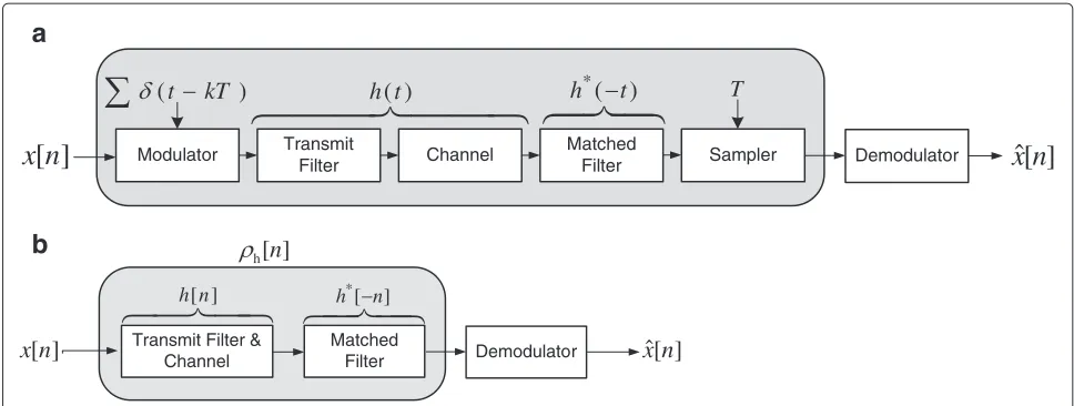
Consider the single-carrier transmission system and its discrete-time equivalent shown in Figure 1a,b, whereT is the symbol duration and h(t) denotes the received pulse (or the overall transmit filter and channel impulse response) with durationTh. Let
ρh[n]=
∞
−∞h(t)h
∗(t−nT)dt (1)
denote the sampled autocorrelation function of h(t) at time n, where ∗ denotes complex conjugate operation. The parameterEh ≡ ρh[0] is the received pulse energy, ρh[n] for n > 0 is called the postcursor inter-symbol interference (ISI), i.e., the ISI from past data symbols, andρh[n] for n < 0 is called the precursor ISI, i.e., the ISI from future data symbols [1]. The folded spectrum
*Correspondence: [email protected]
1Department of Electrical Engineering, Faculty of Engineering, University of Isfahan, Hazarjarib St., Isfahan 81746-73441, Iran
2Department of Electrical Engineering (ESAT-SISTA), KU Leuven, Kasteelpark Arenberg 10, Leuven 3001, Belgium
Full list of author information is available at the end of the article
of h(t),Sh(z), is defined as the z-transform of ρh[n]. Let
Sh(z)=γ2M(z)M∗
1/z∗ (2)
denote the spectral factorization ofSh(z), whereM(z)is monic (i.e.μ[0]=1) and minimum phase withμ[n] being its time domain representation. As a result, M∗(1/z∗) is monic and maximum phase [1]. The spectral factor-ization of Sh(z) can be obtained by Kolmogorov 1939 approach [2].
A zero-forcing equalizer consists of a postcursor equal-izer and a precursor equalequal-izer, a.k.a. forward equalequal-izer. The postcursor and precursor equalizers remove the postcursor and precursor ISI, respectively. The system function of the postcursor equalizer is given by [1]:
E(z)=M−1(z). (3)
SinceM(z)is minimum phase,E(z)can be implemented easily in practicea[1]. Similarly, the system function of the precursor equalizer is given by
D(z)=M∗1/z∗−1. (4)
Modulator Transmit
Figure 1A schematic of the single-carrier transmission system: (a) continuous-time model and (b) discrete-time model.
SinceM(z)is minimum phase,M∗(1/z∗)andD(z)are maximum phase. Therefore, forD(z)to be stable, it must be anticausal, meaning that it cannot be implemented in the general case. Only when D(z) is finite impulse response (FIR) that it can be implemented as a causal filter by introducing some delay [1]. It is easy to show that when the postcursor and precursor equalizers are implemented perfectly, the transfer function of the entire system is the constantγ2, and therefore, the ISI is removed perfectly. Unfortunately,D(z)is not FIR when the received pulse has a finite durationTh, because the inverse of a FIR system is infinite impulse response (IIR)b. A multipath channel is an example of a FIR channel, and together with an FIR transmit filter, it leads to an FIR received pulse and hence an IIR D(z). An example of a system with a FIR trans-mit filter is the filtered multi-tone (FMT) modulation [3]. Conventionally, an IIR anticausal filter is approximated by truncating and delaying in time leading to a causal FIR fil-ter [1]. In this paper, we call this scheme the truncate and delay (T&D) scheme.
In this paper, we propose an alternative scheme to address this problem, namely block transmission-based time-reversed equalization (BT-RTE). The basic idea is to adopt block transmission and implement the precursor equalizer by a time reversal within each block and using a practical minimum phase filter. The idea of using block transmission and reversing the received symbol stream in each block in equalization has been considered in a few articles before. In [4], a decision feedback equalizer (DFE) is operated on a time-reversed stream in order to achieve a better performance in maximum phase channels. In [5], bidirectional DFE has been proposed in which two DFE’s operate on the received block and the time-reversed received block. Then, the two outputs are compared, and if the decoded bits are different for the two streams
(i.e., conflicting decisions), the more likely bit is chosen comparing the corresponding Euclidean metrics. In [6], an improved receiver structure is proposed by trellis-based conflict resolution. Time reversal is also used in the con-text of antenna arrays [7], multiple-input multiple-output systems [8], and space-time block coding [9].
The techniques proposed in [4,5] and [6] do not con-sider matched filtering. Therefore, precursor ISI cancel-lation is not considered. Focusing on linear zero-forcing equalizers, in this paper we consider matched filtering and propose a simple linear equalizer to remove precursor ISIc. We show that the ISI can be removed perfectly using the proposed scheme. By means of a numerical exam-ple, we show that the proposed scheme achieves improved performance compared to the T&D-based equalizer in terms of transmission rate, delay, and implementation complexity.
2 Block transmission-based time-reversed equalization
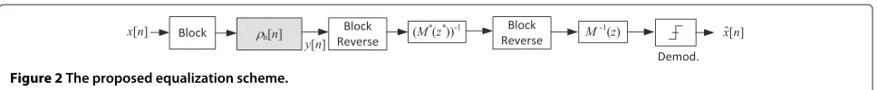
Figure 2The proposed equalization scheme.
It is easy to show that the proposed three-step pro-cedure is equivalent to a filter with the desired pre-cursor equalizer system function (M∗(1/z∗))−1. Let y[n] denote the signal at the output of the matched filter with z-transform Y(z). The z-transform for the reversed signaly[−n] isY(1/z). Thez-transform of the output of the filter with transfer function(M∗(z∗))−1is (M∗(z∗))−1Y(1/z). Finally, thez-transform of the signal when it is reversed back in time is(M∗(1/z∗))−1Y(z). For this to work properly, we need to avoid block inter-ference (IBI), which can be done by adding a guard interval with length equal to the total transmit filter and chan-nel lengthd, at the end of each blocke. In this paper, we assume that the transmission is idle during the guard time. Another approach is the use of a cyclic prefix during the guard time [10].
3 Numerical example and analysis
In this section, we study a practical example with a two-tap FIR channel. Let
h(t)=g(t)−cg(t−T) (5)
denote the channel impulse response, where g(t) is a real-valued pulse with unit energy and durationT, c is a complex-valued constant, and T is the symbol dura-tion. The discrete model of the channel is then h[n]= δ[n]−cδ[n−1]. The matched filter’s impulse response for this channel is h∗(−t) = g(−t) − c∗g(−t−T) or in the discrete domain h∗[−n] = δ[n]−c∗δ[n+1] with z-transformH∗(1/z∗) = 1 − c∗z, whereH(z) = 1−cz−1is the matched filter transfer function. In prac-tice, we have to delay the matched filter by 2T (or one sample in discrete domain) to obtain a causal filter, which following [1] we ignore here. Therefore, ρh[n]=
1+ |c|2δ[n]−c∗δ[n+1]−cδ[n−1] andSh(z) = 1+ |c|2−c∗z−cz−1.
The spectral factorization of Sh(z) depends on the amplitude ofc. Assuming|c|<1, we obtainM(z) =1− cz−1. Thus,E(z)=1−cz−1−1andD(z)=(1−c∗z)−1. For the postcursor and precursor equalizers to be sta-ble, the region of convergence (ROC) should include the unit circle [11]. Since |c| < 1, stability necessitates the ROC to be|z| > |c| for the postcursor equalizer E(z). Moreover, the impulse response of the postcursor equal-izer is calculated to bee[n]= cnu[n] (where u[n] is the unit step function), which is a causal filter and can be implemented using a feedback loop with open loop gain 1−M(z)[1]. ForD(z), the stability requirement leads to
the ROC |z| < |c|−1. Therefore, the impulse response is calculated to bed[n]= c∗−nu[−n], which is an anti-causal filter. Using similar reasoning, for|c|>1, we obtain M(z)=1−c∗z,E(z)=(1−c∗z)−1,D(z)=1−cz−1−1, e[n]= −c∗−n−1u[n−1], andd[n]= −cnu[−n−1]. Note thatd[n] is again anticausal.
3.1 T&D equalizer
Sinced[n] is an infinite length anticausal filter, it is not practically implementable and can only be approximated based on a T&D operation [1]. Let us first consider the |c|<1 case. If we truncated[n] atn= −L(i.e., setd[n]= 0 forn ≤ −L) and delay it by L−1 samples, we obtain the followingL-tap FIR approximation for the precursor equalizer:
ˆ
d[n]=c∗L−1−n(u[n]−u[n−L]). (6)
Thez-transform ofdˆ[n] is
ˆ
D(z)=c∗L−11−(c
∗z)−L
1−(c∗z)−1 =c
∗Lz(c∗z)−L−1
1−c∗z . (7)
Thus, the overall system transfer function is
Sh(z)Dˆ(z)E(z)=c∗Lz
(c∗z)−L−1=z−L+1−c∗Lz, (8)
and its impulse response ishs[n]=δ[n−L+1]−c∗Lδ[n+1]. Therefore, the output of the system to the inputx[n] is s[n]= x[n−L+1]−c∗Lx[n+1]. As it can be seen, the system is not causal which is because the matched filter is not causal. Note thatx[n−L+1] is the desirable signal (delayed byL−1 samples), and−c∗Lx[n+1] is the residual ISI due to the approximation in the precursor equalizer. IfP ≡ E|x[n]|2, then the desired signal and ISI power at the output of the postcursor equalizer arePandP|c|2L, respectively.
We assume that the channel noise is white and Gaussian with varianceσ2. The noise goes through the matched fil-ter and the equalizers with in total the following transfer function
Hn(z)=c∗Lz
(c∗z)−L−1
Therefore, if we denote the channel noise by φ[n], the noise contribution at the output of the postcursor equal-izer is
From this the noise power is calculated to be
E|ν[n]|2=σ21− |c| 2L
1− |c|2 . (11)
Thus the achievable signal-to-interference-and-noise ratio (SINR) for the T&D equalizer is
SINRT&D=
is the SNR of the channel when ISI is not present, i.e., when the previous symbol is zero. Finally, assuming com-plex symbols with Gaussian distribution, the number of bits that can be transmitted per channel use is obtained by the Shannon capacity formula
CT&D=log2(1+SINRT&D). (14) For the|c|>1 case, we truncated[n] atn= −L−1 and delay it byLsamples to obtain
ˆ
The overall system transfer function and impulse response areSh=z−L−c−Landhs=δ[n−L]−c−Lδ[n]. The system transfer function for the noise is
Hn(z)= −c−L
1−cLz−L
1−cz−1 , (17)
and the noise power is equal to
E|ν[n]|2=σ2|c|−21− |c|
−2L
1− |c|−2 . (18) Finally, the achievable SINR is
SINRT&D= of bits per channel use can be obtained by (14).
3.2 BT-RTE
Now, let us analyze the performance of the BT-RTE for this channel. Using the BT-RTE, the ISI is compensated perfectly and the overall transfer function is 1. The chan-nel noise goes through the matched filter and the pre- and postcursor equalizers. It is easy to show that the system transfer function for the channel noise for both |c| < 1 and|c|>1 cases isH−1(z)=1−cz−1−1; however, the noise power is different for the two cases as the pre- and postcursor equalizers are implemented differently as dis-cussed before. For the|c|<1 case, the noise power for the n-th symbol in the block is calculated by
E|ν[n]|2=σ21− |c| 2n
1− |c|2 . (20)
For the|c|>1 case, the noise power is calculated by
E|ν[n]|2=σ2|c|−2
whereKis the block length. The achievable SNR (or SINR) on then-th received symbol using the BT-RTE is
SNRBT-RTE,n=fn−1SNR◦, (22)
is the noise power boost factor on then-th symbol due to the equalization.
For the BT-RTE scheme, we need a guard interval of length one in each block for this channel to avoid IBI. Assuming symbol by symbol detection, the average num-ber of transmitted bits per channel use is calculated by
CBT-RTE=
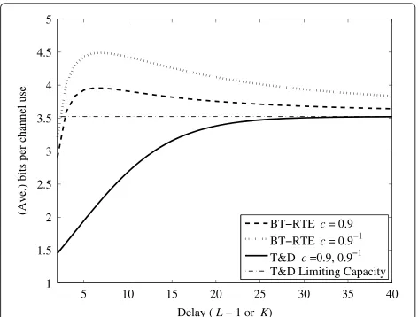
The (average) number of transmitted bits per channel use for the two schemes is plotted vs. the delay in Figure 3 for c = 0.9 and 0.9−1 and SNR◦ = 20 dB. Note that the delay for the T&D equalizer isL−1, and the maxi-mum delay of the symbols in a block isKfor the BT-RTE scheme. As it can be seen, the achievable rate for the BT-RTE scheme is significantly higher than for the T&D equalizer forc=0.9 and 0.9−1, i.e., when the channel zero is close to the unit circle. In fact, the T&D scheme is an approximation of the zero-forcing equalizer (ZFE), which is known to boost the channel noise in this case [12]. On the other hand, the BT-RTE is a perfect implementation of the ZFE; however, it does not boost the noise power outside the block using a guard time.
Moreover, it can be noticed that the BT-RTE scheme’s achievable rate is not always an increasing function of the block size (or delay)K. In fact, the peak point is located atK =7, which is about 27.48% higher than the limiting capacity of the T&D scheme, and a block length ofK=3 is enough to reach the limiting capacity. This is because the loss due to the guard interval decreases by increas-ing the block lengthK. However, the SNR also decreases by increasingn(1≤n<K)in (22). As a result, the aver-age rate is not necessarily an increasing function ofK. If we ignore the loss due to the guard time, the achievable bit rate is always a monotically decreasing function of the block length approaching the limiting capacity of the T&D scheme in limit.
Finally, note that the computational complexity of the BT-RTE scheme is independent of the block sizeK and depends on the channel impulse response length. How-ever, the computational complexity of the T&D scheme grows almost linearly with the filter lengthL.
4 Conclusion
Precursor ISI equalizers are not realizable in many situ-ations and can only be approximated by truncating and delaying the ideal (anticausal) filter impulse response. In this paper, we have proposed a block transmission scheme in which the precursor equalizer is implemented in reversed time. We have shown that this filter is min-imum phase and practically implementable. By means of a numerical example, we have shown that the proposed system can achieve limiting rates with smaller delays and lower computational complexity compared to a scheme
based on truncating and delaying when the zeros of the channel are close to the unit circle.
Endnotes
a We assume thatM(z)does not have a zero on the unit
circle.
b Indeed the inverse of rational IIR systems is also IIR
except for all-pole IIR systems.
c Nevertheless, a higher performance can be achieved
by the use of minimum mean squared equalizer (MMSE), decision feedback equalizer, or maximum likelihood (ML) decoding instead of linear zero-forcing equalization.
d In discrete time, the length of the guard interval is the
overall transmit filter and channel impulse response length minus one.
e For this to be valid, the blocks should be separated at
the output of the channel; otherwise, the matched filter length should also be added to the length of the guard interval.
Competing interests
The authors declare that they have no competing interests.
Authors’ information
ARF is with the Department of Electrical Engineering, Faculty of Engineering, University of Isfahan, Hazarjarib St., Isfahan, 81746-73441, Iran. He was with the Department of Electrical Engineering (ESAT-SISTA), KU Leuven, Kasteelpark Arenberg 10, Leuven, 3001, Belgium, working on this research project until February 2012.
Acknowledgements
This research work was carried out in part at the ESAT Laboratory of KU Leuven, in the frame of the following:
• Concerted Research Action GOA-MaNet
• The Belgian Programme on Interuniversity Attraction Poles initiated by the Belgian Federal Science Policy Office IUAP P7/23 BESTCOM (2012-2017)
• KU Leuven Research Council CoE PFV/10/002 ‘Optimization in Engineering’ (OPTEC)
• IWT Project ‘PHANTER: PHysical layer and Access Node TEchnology Revolutions: enabling the next generation broadband network.’
The scientific responsibility is assumed by its authors.
Author details
1Department of Electrical Engineering, Faculty of Engineering, University of
Isfahan, Hazarjarib St., Isfahan 81746-73441, Iran.2Department of Electrical
Engineering (ESAT-SISTA), KU Leuven, Kasteelpark Arenberg 10, Leuven 3001, Belgium.3IBBT Future Health Department, KU Leuven, Kasteelpark Arenberg
10, Leuven 3001, Belgium.4Bell Labs, Alcatel-Lucent, Copernicuslaan 50, Antwerp 2018, Belgium.
Received: 19 March 2013 Accepted: 20 October 2013 Published: 14 November 2013
References
1. JR Barry, EA Lee, DG Messerschmitt,Digital Communication, 3rd edn. (Kluwer, Boston, 2003)
2. A Papoulis,Signal Analysis, vol. 191 (McGraw-Hill, New York, 1978) 3. G Cherubini, E Eleftheriou, S Olcer, Filtered multitone modulation for very
high-speed digital subscriber lines. IEEE J. Sel. Areas Commun.20(5), 1016–1028 (2002)
5. JK Nelson, AC Singer, U Madhow, C McGahey, BAD: bidirectional arbitrated decision-feedback equalization. IEEE Trans. Commun.53(2), 214–218 (2005)
6. CW Wong, JM Shea, Y Lee, Hard-and soft-output trellis-based conflict resolution for bidirectional decision feedback equalization. IEEE Trans. Wireless Commun.8(7), 3780–3788 (2009)
7. P Kyritsi, P Stoica, G Papanicolaou, P Eggers, A Oprea, Time reversal and zero-forcing equalization for fixed wireless access channels, inConference Record of the Thirty-Ninth Asilomar Conference on Signals, Systems and Computers, 2005(Pacific Grove, 29 October to 1 November 2005), pp. 1297–1301
8. J Choi, A bi-directional zero-forcing BLAST receiver. IEEE Trans. Signal Process.52(9), 2670–2673 (2004)
9. F Petré, G Leus, L Deneire, M Engels, M Moonen, H De Man, Space-time block coding for single-carrier block transmission DS-CDMA downlink. IEEE J. Sel. Areas Commun.21(3), 350–361 (2003)
10. G Fettweis, M Krondorf, S Bittner, GFDM - Generalized frequency division multiplexing, inIEEE Semiannual Vehicular Technology Conference, VTC’09-Spring(Barcelona, 26–29 April 2009), pp. 1–4
11. AV Oppenheim, RW Schafer,Discrete-Time Signal Processing, 3rd edn. (Prentice-Hall, Upper Saddle River, 2010)
12. J Proakis, M Salehi,Digital Communications, 5th edn. (McGraw-Hill, New York, 2008)
doi:10.1186/1687-6180-2013-171
Cite this article as:Forouzanet al.:Precursor inter-symbol interference removal by block transmission-based time-reversed equalization.EURASIP Journal on Advances in Signal Processing20132013:171.
Submit your manuscript to a
journal and benefi t from:
7Convenient online submission
7Rigorous peer review
7Immediate publication on acceptance
7Open access: articles freely available online
7High visibility within the fi eld
7Retaining the copyright to your article