Scholarship at UWindsor
Scholarship at UWindsor
Electronic Theses and Dissertations Theses, Dissertations, and Major Papers
2013
A Novel Globally Optimized Instantaneous Torque Ripple
A Novel Globally Optimized Instantaneous Torque Ripple
Minimization Method in Switched Reluctance Motors with Matrix
Minimization Method in Switched Reluctance Motors with Matrix
Converter Drives
Converter Drives
Syeda Fatima S. Ghousia
University of Windsor
Follow this and additional works at: https://scholar.uwindsor.ca/etd
Recommended Citation Recommended Citation
Ghousia, Syeda Fatima S., "A Novel Globally Optimized Instantaneous Torque Ripple Minimization Method in Switched Reluctance Motors with Matrix Converter Drives" (2013). Electronic Theses and Dissertations. 4913.
https://scholar.uwindsor.ca/etd/4913
This online database contains the full-text of PhD dissertations and Masters’ theses of University of Windsor students from 1954 forward. These documents are made available for personal study and research purposes only, in accordance with the Canadian Copyright Act and the Creative Commons license—CC BY-NC-ND (Attribution, Non-Commercial, No Derivative Works). Under this license, works must always be attributed to the copyright holder (original author), cannot be used for any commercial purposes, and may not be altered. Any other use would require the permission of the copyright holder. Students may inquire about withdrawing their dissertation and/or thesis from this database. For additional inquiries, please contact the repository administrator via email
A Novel Globally Optimized Instantaneous Torque Ripple Minimization Method in Switched Reluctance Motors with Matrix Converter Drives
By
Syeda Fatima Ghousia
A Dissertation
Submitted to the Faculty of Graduate Studies
through the Department of Electrical and Computer Engineering
in Partial Fulfillment of the Requirements for the Degree of Doctor of Philosophy
at the University of Windsor
Windsor, Ontario, Canada
2013
by
Syeda Fatima Ghousia
APPROVED BY:
__________________________________________________ Sheldon S. Williamson, External Examiner
Department of Electrical and Computer Engineering, University of Concordia
__________________________________________________ Nadir Zamani,
Department of Mechanical Engineering, University of Windsor
__________________________________________________ Govinda Raju,
Department of Electrical and Computer Engineering, University of Windsor
__________________________________________________ Jonathan Wu,
Department of Electrical and Computer Engineering, University of Windsor
__________________________________________________ Xiang Chen,
Department of Electrical and Computer Engineering, University of Windsor
__________________________________________________ Narayan C. Kar, Advisor
Department of Electrical and Computer Engineering, University of Windsor
iii
0B
DECLARATIONOFORIGINALITY
I hereby certify that I am the sole author of this thesis and that no part of this
thesis has been published or submitted for publication.
I certify that, to the best of my knowledge, my thesis does not infringe upon
anyone’s copyright nor violate any proprietary rights and that any ideas, techniques,
quotations, or any other material from the work of other people included in my thesis,
published or otherwise, are fully acknowledged in accordance with the standard
referencing practices. Furthermore, to the extent that I have included copyrighted material
that surpasses the bounds of fair dealing within the meaning of the Canada Copyright
Act, I certify that I have obtained a written permission from the copyright owner(s) to
include such material(s) in my thesis and have included copies of such copyright
clearances to my appendix.
I declare that this is a true copy of my thesis, including any final revisions, as
approved by my thesis committee and the Graduate Studies office, and that this thesis has
iv
1B
ABSTRACT
The tangential component of electromagnetic force in switched reluctance motors
(SRM) produces the desired torque which fluctuates with rotor position due to the doubly
saliency in physical structure of SRM. The conventional methods are insufficient to
completely compensate for the intrinsic behavior due to double saliency.
This dissertation proposes a novel method of eliminating the torque ripple in the
instantaneous torque profile of SRM and a method to generate the precise reference phase
current waveforms for even open loop operational design through global optimization.
For the purpose of implementation of the proposed method, a non-sinusoidal DC matrix
converter is also proposed to generate such waveforms without using multiple source
voltages and to be able to use the drive in electric vehicle applications where a battery
system is available for DC voltage sources.
The experimentally-obtained characteristics are used for finding the optimal
solution for torque ripple reduction. FEA is used to investigate the accurate EM force and
its radial and tangential components using volume integration method. The proposed
global optimization method can give a precise solution for this non-linear problem.
Therefore a modified fast-filled method is proposed to balance out the crests and troughs
of the torque ripples throughout the operation of SRMs. A set of novel reference current
waveforms are generated for feed-forward torque control.
Comparative analyses with the torque and current profiles of conventional
methods are performed to prove the elimination of ripple up to less than 1% by using the
proposed method. Therefore, it is concluded that the advanced on and delayed
turn-off angles with gradual rise and fall significantly eliminate the ripple.
Inverter topology requirement for SRM is geometry-dependent. A multi-level
converter is more suitable to generate the required position-dependent phase current.
Matrix converters can be used for finer control on flexible current profiling. Therefore, a
non-sinusoidal DC matrix converter is proposed to generate the required phase current
waveforms from a single DC source and to accommodate the changes if required
accurately. Three reduced-switching states schemes were tested with matrix converter
v
2B
DEDICATION
This dissertation is dedicated to my incredibly wonderful husband, Zulfiqar Ali Qureshi (ZAQ), and my beautiful and precious daughters Duaa and Michelle. Thank you for your love, support, patience, and numerous sacrifices throughout my PhD program. This thesis and the pursuit of my goals would not have been possible without you. I give my deepest expression of love and appreciation for the encouragement that you gave and the sacrifices you made during this graduate program. Thank you for the support and company during late nights work.
Duaa and Michelle: Thank you for your patience, encouragement, for making me laugh, and for providing great joy, beauty, and truth to my life. Both of you has shown me that learning is a life-long process. I have learned so much from both of you. I love you more than I can say, and I am extremely fortunate and proud to be your mother. Thank you for being there for each other too and listening to your daddy with remarkable patience whenever mommy was busy in the nights.
vi
3B
ACKNOWLEDGEMENTS
I am thankful to Allah (God) for his uncountable blessings and merciful
guidance to finish this dissertation successfully. I am also thankful to my prophet
Muhammad (peace be upon him and his family) for being the role model for me and
teaching me the importance of seeking knowledge in a human life.
After that I am indebted to many people who have been an integral part of my
research and supportive throughout my PhD program. I am most grateful to Dr. Narayan
C. Kar for taking me under his wing as a Ph.D. student, his everlasting support and
enthusiasm, his advices, humor and positive attitude when things did not go as planned
(countless times!), handling with grace the delicate balance of guidance while allowing
me to be independent with my research, and finally on a personal level, for being my
academic big brother and supportive of my growing family, which includes my husband,
my daughters and myself and for being such a wonderful mentor and providing me with
support, guidance, and patience throughout this research.
I would like to express my gratitude to my other committee members Dr. Raju,
Dr. Zamani, Dr. Wu, and Dr. Chen, for their valuable advice and feedback. I would also
like to thank Andria Ballo, the Graduate Secretary, ECE department, for her resourceful
support and friendliness. I am thankful to all my colleagues in the department and
chargelabs specifically for their encouragements and supports.
And finally, I could not have done this without the love and support of my
family. I would also like to thank my parents for visiting me and staying with me in
Canada for the sake of completion of my dissertation. I can’t thank my mom enough. She
made me whaever I am. Thanks to my bundles of endless joy Duaa and Michelle. I also
hope that as your curiosity grows, so will your love of knowledge, research and
reasoning. At the end, I like to thank my husband, ZAQ who has been so incredibly
supportive during my studies. He also has this uncanny ability to stay calm, hopeful, and
patient in the midst of disaster, which has made the process of finishing a dissertation,
searching for jobs, and always available for taking care of two young children while
himself going through the same simultaneously i.e. busy with his own research and his
own dissertation. Thank you, ZAQ. You are the greatest gift of Allah to me. I can only
vii
TABLE OF CONTENTS
DECLARATION OF ORIGINALITY ... iii
ABSTRACT ... iv
DEDICATION ... v
ACKNOWLEDGEMENTS ... vi
LIST OF TABLES ... xi
LIST OF FIGURES ... xiv
LIST OF ABBREVIATIONS/ SYMBOLS ... xix
NOMENCLATURE ... xxi
Chapter 1 INTRODUCTION ... 1
1.1 Research Background ... 1
1.2 Research Objectives ... 4
1.3 Research Approach And Key Contributions ... 5
1.4 Thesis Organization ... 7
Chapter 2 OVERVIEW OF SWITCHED RELUCTANCE MOTORS ... 10
2.1 Introduction ... 10
2.2 Distinctive Features of SRM ... 10
2.3 Traditional SRM Design ... 12
2.4 Identifying SRM Mechanical Design ... 14
2.5 Identifying SRM Electrical Design ... 14
2.6 SRM Electromagnetic Characterization ... 15
2.7 Basic Principles of Operation ... 16
viii
2.9 Control Techniques for SRM ... 19
2.10 Feasibility Analysis for HEV Applications ... 19
2.11 Options in Research Directions for SRM Drives ... 20
Chapter 3 DEVELOPMENT OF FINITE ELEMENT ANALYSIS MODEL ... 22
3.1 Introduction ... 22
3.2 Finite Element Modelling Of the 8/6 SRM ... 24
3.3 Machine Geometrical Model ... 24
3.4 Machine Magnetic Properties ... 25
3.5 FEM Discretization ... 26
3.6 Finite Element Analysis Results ... 30
Chapter 4 INVESTIGATION OF EM FORCE DISTRIBUTION ... 42
4.1 Introduction ... 42
4.2 Computation of Electromagnetic Forces ... 44
4.3 The Virtual Wok Method ... 45
4.4 Maxwell’s Stress Method ... 46
4.5 Tuneable Volume Integration Method ... 46
4.6 Radial Flux Densities and Stresses ... 47
4.7 Tangential Flux Densities and Stresses ... 49
4.8 Dynamic Analysis of Torque and EM Force ... 56
4.9 Force Calculation Using Tuneable Volume Integration Method ... 56
Chapter 5 INTEGRATION OF MULTI-LEVEL AND MULTIPHASE EXCITATION ... 59
5.1 Introduction ... 59
ix
5.3 Control Variables for Torque Profiling in SRM ... 61
5.4 Regions of Interests in EM Characteristics ... 62
5.5 Comparison of DAC and MLE ... 65
5.6 Region-Wise Applicability ... 66
5.7 Analysis of Dwell Angle Parameters Control ... 66
5.8 Percentage of Overlapping ... 67
5.9 Duration of the Dwell Angle ... 68
5.10 Advanced Conduction Angle ... 68
5.11 Delayed Tail Angle... 69
5.12 An Optimized Combination of All Parameters ... 69
5.13 Position Dependent Multi-Level Current Excitation ... 70
Chapter 6 PROPOSED GLOBAL NLP OPTIMIZED TORQUE RIPPLE ELIMINATION METHOD ... 77
6.1 Introduction ... 77
6.2 Electromagnetic Torque Profile Measurements ... 80
6.3 Parametric Analysis of Torque and Phase Current Profiles ... 82
6.4 Quantitative Analysis of Torque and Current Profiles ... 86
Chapter 7 IMPLEMENTATION THROUGH A NON-SINUSOIDAL MATRIX CONVERTER ... 92
7.1 Introduction ... 92
7.2 Classical SRM Multilevel Converter Topologies ... 94
7.3 Proposed Non-Sinusoidal Matrix Converter ... 96
7.4 Mathematical Model and Design of MC ... 97
7.5 Analysis of Commutation Strategies for Allowed Switching States ... 99
x
Chapter 8 CONCLUSIONS ... 106
REFERENCES ... 108
Appendix A: Lab SRM Experimental Data ... 120
Appendix B: Experimental Data Matrix Construction ... 121
Appendix C: Comparative Analyses Of Proposed Method For Torque Minimization With Conventional Methods ... 139
Appendix D: Performance Evaluation of Matrix Converter ... 177
LIST OF PUBLICATIONS ... 181
xi
4B
LISTOFTABLES
Table 2.1 Comparative Feasibility Analysis of Various Motors for HEV
Applications. ... 21
Table 3.1 8/6 SRM Geometrical Dimensions. ... 29
Table 3.2 8/6 SRM Component Materials. ... 29
Table 3.3 Torque Profile Discrepansies Between the Experimental Values and
FEA Model. ... 33
Table 6.1 Comparative Torque Analysis of the Proposed Optimization Method. ... 91
Table 7.1 Comparative Torque Analyses of the Matrix Converter
Configurations. (At 45 A) ... 102
Table A.1 2D-Flux Characteristics of the In-house 1 hp SRM. ... 120 Table B.1 4D Primary Phase Matrix Constructed from the Experimental
Results for Global Optimization Method (0-16 A). ... 121
Table B.2 4D Primary Phase Matrix Constructed from the Experimental
Results for Global Optimization Method (17-33 A). ... 123
Table B.3 4D Primary Phase Matrix Constructed from the Experimental
Results for Global Optimization Method (34-50 A). ... 125
Table B.4 4D Secondary Phase (#1) Matrix Constructed from the Experimental
Results for Global Optimization Method (0-16 A). ... 127
Table B.5 4D Secondary Phase (#1) Matrix Constructed from the Experimental
Results for Global Optimization Method (17-33 A). ... 129
Table B.6 4D Secondary Phase (#1) Matrix Constructed from the Experimental
Results for Global Optimization Method (34-50 A). ... 131
Table B.7 4D Secondary Phase (#2) Matrix Constructed from the Experimental
xii Table B.8 4D Secondary Phase (#2) Matrix Constructed from the Experimental
Results for Global Optimization Method (17-33 A). ... 135
Table B.9 4D Secondary Phase(#2) Matrix Constructed from the Experimental Results for Global Optimization Method (34-50 A). ... 137
Table C.1 Instantaneous Torque Profiles by Traditional Method (0-16 A). ... 139
Table C.2 Instantaneous Torque Profiles by Traditional Method (17-33 A). ... 141
Table C.3 Instantaneous Torque Profiles by Traditional Method (34-50 A). ... 143
Table C.4 Instantaneous Phase Current Profiles by Traditional Method (45 A). ... 145
Table C.5 Instantaneous torque profiles by advanced critical angle method (0-16 A). ... 147
Table C.6 Instantaneous Torque Profiles by Advanced Critical Angle Method (17-33 A). ... 149
Table C.7 Instantaneous Torque Profiles by Advanced Critical Angle Method (34-50 A). ... 151
Table C.8 Instantaneous Phase Current Profiles by Advanced Critical Angle Method (45 A). ... 153
Table C.9 Instantaneous Torque Profiles by Additional Boost Method. (0-50 A with an increment of 5 A). ... 155
Table C.10 Instantaneous Torque Profiles by Additional Boost Method. (0-10 A). ... 157
Table C.11 Instantaneous Torque Profiles by Additional Boost method. (11-15 A) ... 159
Table C.12 Desired Torque (TD) Profiles by Proposed Global NLP Optimization Method (0-16 A). ... 161
xiii Table C.14 Desired Torque (TD) Profiles by Proposed Global NLP Optimization
Method (34-50 A). ... 165
Table C.15 Ripples in Instantaneous Torque Profiles (ΔT Profile) Determined for Fast Filling by Proposed Global NLP Optimization Method.(0-16
A). ... 167
Table C.16 Ripples in Instantaneous Torque Profile (ΔT profile) Determined for
Fast Filling by Proposed Global NLP Optimization Method.(17-33
A). ... 169
Table C.17 Ripples in Instantaneous Torque Profile (ΔT profile) Determined for Fast Filling by Proposed Global NLP Optimization Method.(34-50
A). ... 171
Table C.18 Instantaneous Excitation Phase Current Profiles by Proposed Global
Optimization Method (5 A, 10 A, 15 A, 20 A, 25 A). ... 173
Table C.19 Instantaneous Excitation Phase Current Profiles by Proposed Global
Optimization Method (30 A, 35 A, 40 A, 45 A, 50 A). ... 175
Table D.1 Comparison of Instantaneous Phase Current Profiles by Proposed
Method with the Results of the 3 Switching Schemes of Matrix
Converter Design. (at 45 A)... 177
Table D.2 Comparison of Instantaneous initial (Ti), ΔT and Final Torque (Tf) with Ripple (R) Profiles by Proposed Global Optimization Method
xiv
5B
LISTOFFIGURES
Figure 2.1 Snapshot of 1hp- 8/6 laboratory switched reluctance motor. ... 13
Figure 2.2 Interior of an 8/6 switched reluctance motor used in laboratory. ... 13
Figure 3.1 3D FEM solid geometrical model ignoring end-winding effects. ... 28
Figure 3.2 Cross-sectional geometry of the 8/6 SRM and respective dimensions. ... 28
Figure 3.3 Measured Magnetization curve used in the analysis. ... 29
Figure 3.4 Magnetic flux distribution at the two rotor positions for phase 1 excitation. (a) 0° rotor position. (b) 16° rotor position. ... 33
Figure 3.5 Initial and solution mesh for FEM analysis. (a) 2D-view of SRM at 0° rotor position. (b) initial 2D mesh. (c) solution mesh. ... 34
Figure. 3.6 Magnetic flux linkage in phase 1 as a function of the rotor position and excitation current obtained by the FEM and experiments. (a) 3A. (b) 6A. ... 35
Figure. 3.7 Magnetic flux linkage in phase 1 as a function of the rotor position and excitation current obtained by the FEM and experiments. (a) 9A. (b) 12A. ... 36
Figure. 3.8 Magnetic flux linkage in phase 1 as a function of the rotor position and excitation current obtained by the FEM and experiments. (a) 15A. (b) 18A. ... 37
Figure 3.9 Air-gap torque produced on phase 1 as a function of the rotor position and excitation current obtained by the FEM and experiments. (a) 3 A. (b) 6 A.. ... 38
xv Figure 3.11 Air-gap torque produced on phase 1 as a function of the rotor
position and excitation current obtained by the FEM and
experiments. (a) 15 A. (b) 18 A. ... 40
Figure 3.12 Average air-gap torque per phase vs. excitation current by the
experimental and FEM model. ... 41
Figure 4.1 Types of electromagnetic force in SRM. ... 43
Figure 4.2 Comparisons of virtual work method and Maxwell stress tensor
method. ... 45
Figure 4.3 Magnetic flux versus the excitation current for different rotor
positions. ... 48
Figure 4.4 Distribution of magnetic flux density at different rotor positions at 3
ms, 3.4 ms, 4 ms (aligned to semi-aligned positions). ... 50
Figure 4.5 Distribution of magnetic flux density at different rotor positions at
4.4 ms, 5 ms and 5.4 ms (semi-aligned to aligned positions). ... 51
Figure 4.6 Radial flux density patterns for three different rotor positions (0, 15,
30 degrees). ... 52
Figure 4.7 Radial components of flux densities vs. contour position (rotor
position from aligned to unaligned). ... 53
Figure 4.8 Radial components of electromagnetic stresses vs. contour position
(rotor position from aligned to unaligned). ... 53
Figure 4.9 Tangential Flux density patterns for three different rotor positions
(0°, 15°, 30°). ... 54
Figure 4.10 Tangential components of flux densities vs. contour position (rotor
position from aligned to unaligned). ... 55
Figure 4.11 Tangential components of electromagnetic stresses vs. contour
position (rotor position from aligned to unaligned). ... 55
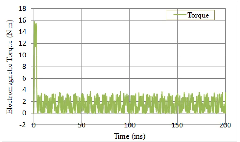
xvi Figure 4.13 Dynamic electromagnetic force and torque on rotor of the SRM with
single phase excitation. ... 57
Figure 4.14 Dynamic behavior of the SRM with single phase excitation in terms of no-load torque. ... 58
Figure 4.15 Electromagnetic force on rotor of the SRM with single phase excitation. ... 58
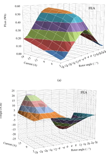
Figure 5.1 Electromagnetic characteristics of the SRM by FEA (a) flux profile. (b) torque profile. ... 63
Figure 5.2 Electromagnetic characteristics of the laboratory SRM (a) flux profile. (b) torque profile. ... 64
Figure 5.3 Block diagram of the feedback control system of the SRM drive. ... 70
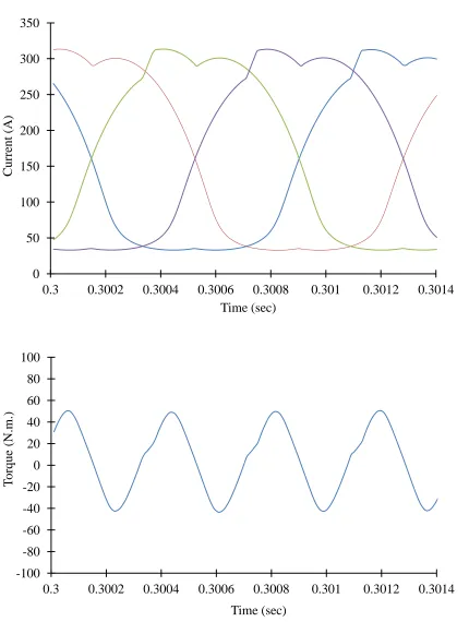
Figure 5.4 Impact of single phase excitation on current and torque profiles. ... 71
Figure 5.5 Simulated excitation current and torque profiles with one of the advanced angle method. (Also known as Multiphase Excitation with 50% overlap.) ... 72
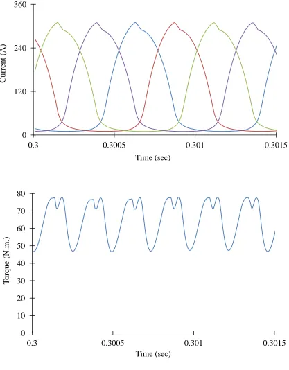
Figure 5.6 Simulated torque and current profiles with maximum advanced angle selection. ... 73
Figure 5.7 Variations in Torque and Current Profiles by delayed turn-off angle selection. ... 74
Figure 5.8 Simulated torque and current profiles by advanced turn-on and delayed turn-off angle selection. ... 75
Figure 6.1 Experimental setup of SRM for locked rotor test with In-house SRM. ... 83
Figure 6.2 3D FEA model of the In-house SRM used in the investigations. ... 83
Figure 6.3 Electromagnetic characteristics of the in-house SRM used. ... 84
xvii Figure 6.5 Instantaneous torque profile by the proposed method, traditional,
advanced angle and additional boost method with primary phase
current at 30 A. ... 88
Figure 6.6 Instantaneous torque profile by the proposed method, traditional,
advanced angle and additional boost method with primary phase
current at 15 A. ... 89
Figure 6.7. Traditional single-phase excitation current profiles at 45 A (I1: phase
1, I2: phase 2, I3: phase 3, and I4: phase 4)... 89
Figure 6.8 Advanced critical angle excitation current profiles at 45 A
(I1: phase 1, I2: phase 2, I3: phase 3, and I4: phase 4). ... 90
Figure 6.9 Additional boost multi-level excitation current profiles at 45 A
(I1: phase 1, I2: phase 2, I3: phase 3, and I4: phase 4). ... 90
Figure 6.10 Proposed optimized excitation current profiles at 45 A (I1: phase 1,
I2: phase 2, I3: phase 3, and I4: phase 4). ... 91
Figure 7.1 A classical ac-ac matrix converter circuit. ... 94
Figure 7.2 Possible configuration of a sparse matrix converter for SRM with dc
voltage. ... 98
Figure 7.3 Comparisons of instantaneous torque profiles by the implementation
of proposed method using Matrix Converter at 45 A with the
proposed method. ... 103
Figure 7.4 Comparison of torque profiles by the implementation through matrix
converter at 45 A with the proposed method and conventional
methods. ... 104
Figure 7.5 Excitation current profiles at 45 A using matrix converter with 9 DC
levels. (I1: phase 1, I2: phase 2, I3: phase 3, and I4: phase 4). ... 104
Figure 7.6 Excitation current profiles at 45 A using matrix converter with 7 dc
xviii Figure 7.7 Excitation current profiles at 45 A using matrix converter with 12 dc
xix
6B
LISTOFABBREVIATIONS/SYMBOLS
AC : Alternating Current
BDS : Bidirectional Switch
BLDC : Brushless DC motors
DAC : Dwell Angle Control
DC : Direct Current
DTC : Direct Torque Control
EMF : Electromagnetic Force
EMI : Electromagnetic Interference
EV : Electric Vehicles
FC : Frequency Converter
FEA : Finite Element Analysis
FEM : Finite Element Method
FPGA : Field Programmable Gate Arrays
HEV : Hybrid Electric Vehicle
HP : Horse Power
IGBT : Insulated Gate bipolar Transistor
IC : Integrated Circuits
IEC : International Electro-technical Commission
IM : Induction Machines
IPM : Interior Permanent magnet
ISO : International Standardization Organization
LF : Lorenz Force
MC : Matrix Converter
MLE : Multi-Level Excitation
MMF : Magneto Motive Force
MST : Maxwell’s Stress Tensor
NLP : Non-Linear Problems
PM : Permanent Magnet
xx RB : Reverse Blocking
RPM : Revolutions Per Minute
SF : Saliency Force
SM : Synchronous Machines
SRM : Switched Reluctance Motors
xxi
7B
NOMENCLATURE
t : Tangential stress
n : Normal or radial stresses
Bt : Tangential flux density Bn : Normal or radial flux density J : Current density
: Magnetic flux
: Rotor position
i : Instantaneous phase current pitch : Dwell angle
m : modulation index c : Critical rotor position j : Current phase
Ti,() : Instantaneous torque at ij() k : Torque constant ratio
kT,j : Torque constant ratio for phase j
k0 : Torque constant ratio between neighboring phases Rt() : Torque ripple at
on : Turn-on angle
: Motor speed
off : Turn-off angle
x
1
Chapter 1
8B
INTRODUCTION
1.1 Research Background
Recently, Switched reluctance motor (SRM) drives have received more and
more attention in the field of high performance drives because of their simple
construction, robust design, lower weight and size due to the absence of rotor windings,
variable speed operations, higher torque-to-inertia ratio, inexpensive, reliability,
ruggedness, fault tolerance, reduced number of power switches requirement, and
relatively low manufacturing costs leading to attractiveness for industrial and electrical
vehicle (EV) applications [1], [2]. An SRM can produce high torque at low speed.
Furthermore, these features make SR drives a viable alternative to other commonly used
motors like AC, BLDC, PM Synchronous or universal motors for numerous
applications[3], [4]. A well designed SRM drive system matches the performance of the
conventional ac motor drives and it has several advantages over them due to unipolar
rotor torque. However, it still needs broad industry acceptance due to his high torque
ripple, excessive machine vibrations, and undesirable acoustic noise [5].
Any electrical machine has to be thoroughly studied in the design stage for its
static and dynamic performance before the finalization of its design and/or control.
Therefore, the first phase of the research work consists of the complete analysis of the
electromagnetic characteristics of the machine in terms of its electromagnetic force, flux,
2 SRMs are basically characterized by a strongly non-linear behaviour due to its
typical operation in a magnetic saturation region; there is no analytical equation to
describe their behaviours [7]. The numerical determination can be based on
finite-element method (FEM) analysis, conveniently used to obtain machine magnetic vector
potential values in the presence of complex magnetic materials [8]. Therefore, significant
research in the development of more appropriate numerical algorithms for a FEM study
of SR machines has been done in the past years [9]. Many authors have proposed
analytical methods to predict the unsaturated magnetic characteristics of SRM as in for an
8/6 SRM and in only for the unaligned inductance [10]. However these methods are quite
laborious and cannot be used to predict the dynamic behaviour of the machine. Therefore
an accurate FEA is required to match the fingerprints of the machine under study.
Due to the absence of windings on the rotor, stored energy in the air gap of the
SRM is almost entirely converted into the mechanical form except for the iron losses in
the rotor [11]. This magneto-mechanical energy conversion is manifested in the
distribution of the radial and tangential force components around the circular air gap [12].
Tangential component of the force is acting on the rotor and stator poles resulting in
generation of the electromagnetic torque on the rotor and tangential vibration of the stator
poles. The radial component of the force, on the other hand, appears as a by-product and
mainly contributes to the radial vibration of the stator which is known to be the main
origin of acoustic noise in SRM drives [13], [14]. The ripple in the instantaneous torque
profile decreases the efficiency [15]. Therefore, the study of electromagnetic force
distribution in all directions is also important in order to keep the tangential component
3 The reduction of torque ripple is the main target in research for designing a
variable drive system with switched reluctance motors (SRM) for higher torque density
and better efficiency [5]. This ripple is mainly due to the transition of excitation current
between the adjacent phases. Precise control of turn-on and turn off angle is required to
smooth the torque [16]. Effects of selecting the turn-on and turn-off angles are studied in
detail with simulation results. It is observed that with the extended turn-on and turn off
angles, the precise selection of turn-on and turn off angle can alter the shape of the
excitation current in the stator coil and its point of overlapping with the adjacent coil.
Therefore the transition between different phases can be smoothed out. The impact of this
alteration on the excitation current and torque ripple as a function of different parameters
of dwell angle is also studied paper. It is found that a sinusoidal current shape can also be
obtained with the proper selection of these parameters.
Keeping the tangential component of the EM force constant throughout the
electrical and mechanical cycle requires constantly varying input current source as well
as the freedom of choosing the rotor position because the amount of torque does not
depend only on the input current but also on the rotor position [17]. A global optimization
method is proposed to balance out the crests and troughs of the torque ripples throughout
the operation. Open loop simulations with precise drive model in the form of its
fingerprints are studied. These fingerprints are actually the intrinsic electromagnetic
characteristics of the machine. It is suggested that the proposed reference current
waveforms will improve the performance by compensating for the intrinsic behavior of
the machine which is the non-linear relationships of torque with phase currents and rotor
4
1.2 Research Objectives
Direct torque Control (DTC) methods [18] which are usually employed in
feedback and control system of an electrical drive can only improve the average torque
value in case of SRM and cannot improve the instantaneous torque ripple produced due
to the double saliency structure. This is because when the feedback reaches the command
signal, rotor has already change its position and the input signal requirement changes for
the same EM force with respect to the geometrical structure of the machine [19].
Therefore, different approaches have been adopted by researchers to reduce the
ripple in the torque to improve the percentage of torque ripple in the instantaneous torque
and optimize the benefits of different methods employed for the torque the problem has
to be solved with the adoption of non-linear problem solving approach [20].
There are many approaches to achieve the objectives. Some of them are as follows:
Modification in the geometric structure of the machine such as increasing
the number of poles shapes of poles etc. [21]-[33].
Suggestions to alter the winding configuration such as short-pitch, concentrated coil etc. [34], [35]
Variations in the dwell angle parameters [36]-[38]
Multi-level phase excitation [39]
1. Unipolar switching [40], [41]
2. Bipolar switching [42]
However, among all these solutions, there is still no single solution which can
exactly address all operating conditions and which can compensate for the ripples in all
5 machine modelling and requires an exact model of the machine which is quite
impossible. Therefore, the research objective of this dissertation is to propose a global
non-linear solution which can be applied under all operating conditions.
1.3 Research Approach and Key Contributions
In this section the contributions of this dissertation are presented to fulfil the
objectives discussed in the previous section. Since the research approach is to use the
experimental data instead of a mathematical or analytical model, the first contribution is
the identification of regions of interests individually and the study of co-relation of
geometry with the electromagnetic characteristics (chapter 3).
The second contribution is the evaluation of the deficiencies and inaccuracies of
energy method which is usually employed for modelling and another method is evaluated
to determine the accurate force distribution. On the basis of this accurate force
distribution and its tanegntial component profile, the deffficiencies in each region and its
possible local solutions are evaluated (chapter 4).
The third contribution is the comparative performance evaluation of each local
solution when implemented individually and also simultaneously. Therefore,
optimization of these local solutions is evaluated as a global solution to this non-linear
problem, and the results are analyzed for the extent of their effectiveness and limitations
for the simultaneous implementation. The results are quite desirable. However there are
some adverse effects such as some other sources of ripple generation occurs which are
quite lower as compared to initial problem but it exists. Hence it lowers the benefits from
6 The forth contribution which is one of the two key contributions is the proposal
of applying a modified version of a genetic optimization algorithm known as fast-filled
method for fast filling colors in artificial intelligence which will give a fastest, accurate
and more efficient solution to this problem (chapter 6). It is accurate because it is a
model-free solution because it takes into account the experimental data instead of
approximate models. In such case, there is no chance of propagating the modelling error
into the solution. Since there is no model of the machine, no errors due to parameter
sensitivity or uncertainty is expected. This is because the method is using the actual
values of the machine characteristics and if any of the parameter is changed, for example,
if the winding resistence increases with the passage of time, the machine EM
characteristics will change automatically and only recaliberation will solve the problem.
(FEA model is simply the rebuilding of the machine virtually with exact EM
characteristics for cold test runs).
The fast fill algorithm is a generic algorithm for global optimization techniques.
Therefore, the term global for this solution is significant solution which can work on all
regions of electromagnetic characteristics curves of the machine equally. This will make
the solution geometric-dependent instead of drive operating conditions and speed
dependent. As a result, it also generates a set of exact and unique input phase current
profiles for switching. It also optimizes the results for the minimum variations in input
current.
The last and the other key contribution is the proposal of a design of a
non-sinusoidal matrix converter for the drive to implement these input phase currents. Matrix
7 through modulation and usually works for sinusoidal input and output. However, many
researchers have proposed it for non-sinusoidal output. With no energy storage element
or passive components, the number of active switches and considering the switching
losses and frequency determines the efficieny of the converter. Therefore, the efficiency
is analyzed by reducing the number of switches (using sparse MC) and switching states.
by reducing the number of DC level sensitivity.
The classical matrix converter topology is modified not only for the
non-sinusoidal output but also for the DC input source. A DC source instead of a 3-phase
sinusoidal input source is chosen for feasibility analysis of SRM drive for electric
vehicles whichs run on batteries to be able to achieve any desirable DC level. Since
matrix converters donot have any energy storage element and its power factor can be
fully controlled, it gives a motivation to eliminate the DC link energy storage elements in
electric vehicles by using the matrix converters.
1.4 Thesis Organization
This thesis consists of eight chapters and four appendices. The appendices
consist of matrix data in the form of tables generated to implement the global
optimization method. The raw experimental data set and the processed data set cannot be
plotted as a function and can not be presented accurately in the graph form for detailed
study or future work.
Chapter 2 provides an introduction to a typical market-available traditional
SRM including its distinctive features, motor design, its construction, and basic
operation. It also provides the identifying characteristics of the machine and its typical
8
Chapter 3 presents the details of the development finite element analysis (FEA)
model of the SRM to study the non-linear electromagnetic characteristics of the SRM in
terms of flux and torque with respect to the excitation current and rotor position.
Therefore, comparative analyses of the proposed torque ripple minimization technique
with other typical methods can be performed on this FE model. FEM simulations require
complete information about the geometrical parameters of SRM. It could be used as a
prior stage during the development of the electromechanical system.
Chapter 4 consists of a comprehensive study of the electromagnetic force and
its distribution in tangential and radial directions as well as their desired and adverse
effects on instantaneous torque profile. It also provides the regions of torque profile
where tangential force decreases significantly, therefore, keeping a constant torque
profile is not possible and thus causing ripple. Also the accurate EM force has been
calculated using tunable volume integration method.
Chapter 5 discusses the effects of the dwell angle control parameters in terms
of advanced angle, delayed tail angle and duration of the conduction angle. An
optimization procedure is also adopted for the best possible results in terms of torque
ripple minimization. The results are compared with the effects of these parameters
individually as well as in optimized situation not only in terms of the percentage of the
torque ripple reduction but also the amount of total average generated torque.
Chapter 6 describes the proposed global NLP optimization method for the
torque ripple minimization in detail. Since the torque at any instant is not only dependent
on the position of the rotor but also on the amount of current in the excitation coil.
9 current excitation can provide a better control on keeping the desired instantaneous
torque level constant. It also includes the comparative analysis of the results of global
NLP optimization method with conventional methods. A set of reference excitation
current waveforms are also generated for feed-forward and open-loop operations of SRM.
Chapter 7 proposes the use of the popular ac-ac matrix converter for this
proposed method requirement of variable reference current waveform. A sparse-matrix
converter is simulated to give an example of how a single power source can be used for
multiple levels of required current in different phases of the SRM at the same time as
required. The comparative analysis in terms of torque ripple reduction of the results
obtained by selection of a few of the allowable switching states of the sparse matrix
model is presented with the proposed excitation current waveforms in FEA machine
model.
Chapter 8 presents the conclusions of this research.
Appendix A contains the experimental data obtained from the Lab SRM
Appendix B contains database constructed for the proposed method.
Appendix C contains the instantaneous torque profile obtained by the most
efficient of the typical methods of torque ripple minimization i.e. advanced angle etc.
Appendix D contains the instantaneous torque and phase current profiles
obtained by the matrix converter design after the implementation of the global NLP
10
Chapter 2
9B
OVERVIEW
OF
SWITCHED
RELUCTANCE
MOTORS
2.1 Introduction
Since, switched reluctance motors (SRM) are gaining wider popularity among
variable-speed drives, some of the SRM design parameters, identifying characteristics
and FEA analyses are presented. SRM has currently been given a considerable attention
in the field of high performance drives. The research work has globally been done in both
industrial and university sectors. They offer the advantages of simple structure, low-cost
construction characterized by an absence of magnets and rotor winding, high level of
performance over a wide range of speeds fault tolerance, and mechanical robustness,
leading to attractiveness for industrial and electrical vehicle (EV) applications.
Furthermore, the availability and the moderate cost of the necessary electronic
components make SR drives a viable alternative to other commonly used motors like AC,
BLDC, PM Synchronous or universal motors for numerous applications. After the design
verification methods some of the modern control techniques of SRM are also discussed.
2.2 Distinctive Features of SRM
From the literature review, these are some unique features of the traditional
SRM configurations in comparison to other motors available.
Lowest construction complexity, many stamped metal elements especially helpful for the size and weight restrictions on HEV
11 High reliability (no brush wear), failsafe for Inverter (it eliminates the
possibility of a rail-to-rail short circuit) but acoustically noisy
High efficiency
Fault tolerant [43]
Motor EMI good but terrible EMI from Inverter
Driven by multi-phase Inverter controllers [44]-[49]
Sensor-less speed control possible [50]
Higher total system cost than for DC motors.
Inverter ‘shoot-through’ not possible so higher reliability for automotive
Torque ripple can be reduced by advanced control techniques [51]-[57]
Very Robust and high speed operation is possible
High start-up torque and high torque density.
Intrinsically high torque ripple (i.e. high torque pulsation at low speed)
may cause noise and vibration if mechanical tolerances are not held to
close limits.
However, it can be reduced by different operational and advanced control
techniques such as electronic switching control for its operation because torque in the
switched reluctance machine is produced by pulses of phase current synchronized with
rotor position. The timing and regulation of these current pulses are controlled by the
drive circuit and the torque control scheme. Several power stage topologies are being
implemented, according to the number of motor phases and the desired control algorithm.
A power stage with two independent power switches per motor phase is the most used
12 power stages of AC induction motors because it eliminates the possibility of a rail-to-rail
short circuit. SRM requires position feedback for motor phase commutation. In many
cases, this requirement is addressed by using position sensors, like encoders, Hall
sensors, etc. The result is that the implementation of mechanical sensors increases costs
and decreases system reliability.
Traditionally, developers of motion control products have attempted to lower
system costs by reducing the number of sensors. A variety of algorithms for sensor-less
control have been developed, most of which involve evaluation of the variation of
magnetic circuit parameters that are dependent on the rotor position.
2.3 Traditional SRM Design
SRM is a rotating electric machine where both stator and rotor have salient poles
(Figures 2.1 and 2.2). Traditional switching can be described as follows:
The motor is excited by a sequence of current pulses applied at each phase
of the stator which are consequently excited, forcing the motor to rotate.
The current pulses need to be applied to the respective phase at the exact rotor position relative to the excited phase.
The inductance profile of SRM is triangular shaped, with maximum inductance at fully aligned position and minimum inductance at unaligned.
The motor creates torque in the direction of increasing inductance. When the phase is energized in its minimum inductance position, the rotor moves
to the forthcoming position of maximal inductance.
13 Figure 2.1 Snapshot of 1 hp, 8/6 laboratory switched reluctance motor.
14
2.4 Identifying SRM Mechanical Design
The stator winding is comprised of a set of coils, each of which is wound on one
pole. SRMs differ in the number of phases wound on the stator. Each of them has a
certain number of suitable combinations of stator and rotor poles.
Machine Specifications i.e. required Power Output (hp), Speed N (rpm), peak
phase current (A), and ac supply voltage (V). Speed and power output will also fix the
torque to be developed.
Frame Size Selection i.e. IEC standards fix physical dimensions for all
electrical machines according to ISO regulations. Selection of Frame size
fixes all other physical design parameters automatically.
Pole Selection
Stator and Rotor Pole Angle Selection
Preliminary Design Process and Winding Design
Calculation of Average Torque and Minimum Inductance
2.5 Identifying SRM Electrical Design
Analyzing the dynamic behavior requires to determine the following factors
1. Governing Equations: To predict the dynamic performance (average and
peak torques and currents, speed, etc.) of an SRM, it is necessary to solve a
set of differential circuit equations for the appropriate switched conditions
including the mechanical equations.
2. Modeling of non-linear Inductance
15
2.6 SRM Electromagnetic Characterization
A basic traditional mathematical model of SRMs is usually based on the
electrical diagram of the motor, incorporating phase resistance and phase inductance. Any
voltage applied to a phase of the SRM can be described as a sum of voltage drops in the
phase resistance and induced voltages on the phase inductance. The required machine
Specifications i.e. required Power Output (hp), Speed N (rpm), peak phase current (A),
and ac supply voltage (V). Decision of Speed and power output also fix the torque. An
idealized non-linear theory describing the behavior of the motor is readily available, and
a mathematical model is created based on the theory. On one hand, it is assumed to
enable simulation of the SRM system and, on the other hand, development and
implementation of sophisticated algorithms for controlling the SRM is feasible. The
mathematical model of an SRM is then represented by a system of equations, describing
the conversion of electromechanical energy.
The SRM electromagnetic circuit is characterized by non-linear magnetization.
Figure 2.3 describes the dwell angle with respect to magnetic flux, ψ, the phase current, i,
and the motor position, θ. The influence of the phase current is most apparent in the
aligned position, where saturation effects can be observed. In the idealized triangular
inductance profile of a 3-phase of SRM, the individual phases A, B, and C are shifted by
120 electrical degrees relative to each other. The interval, when the respective phase is
powered, is called the dwell angle, θdwell. It is defined by the turn-on angle, θon, and the
16
2.7 Basic Principles of Operation
The motor itself is a low-cost, simply constructed machine. Variable especially high
speed operation is possible, making the motor suitable for high-speed applications, like
hybrid electric vehicles, vacuum cleaners, fans, white goods, etc. However, the
disadvantage of the SRM is the need for shaft position information for proper switching
of individual phases.
Figure 2.3 Dwell angle illustrations in a 3-phase SRM.
Also, the motor structure causes noise and torque ripple. The higher the number
of poles, the smoother the torque ripple, but motor construction and control electronics
become more expensive. In general, torque ripple can also be reduced by advanced
control techniques, such as phase current profiling. Its basic principles of operation are:
The motor is excited by a sequence of current pulses applied at each phase
Aligned Unaligned Aligned
Stator Phase A Rotor
Phase A energizing dwell Position/ time
off_phA
iph
LB
LC LA
17 The current pulses need to be applied to the respective phase at the exact
rotor position
The inductance profile of SRM is triangular shaped, with maximum
inductance when it is in an aligned position and minimum inductance
when unaligned.
When the current pulse is applied to the stator phase, the motor creates torque in the direction of increasing inductance and the rotor moves to the
forthcoming position of maximum inductance.
The profile of the phase current and the magnetization characteristics define the generated torque and thus the speed of the motor.
The influence of the phase current is most apparent in the aligned position, where saturation effects can be observed.
During a standard operation in the commutation phase, just one phase is
powered at a time. The control technique uses fixed turn-on and turn-off angles for
switching the phases. The speed of the motor is controlled by the voltage, applied to the
motor phase using the PWM technique.
2.8 Basic Switching Techniques for PWM Control
At low-speed operation, the pulse width modulation (PWM), applied on the
corresponding switches, modulates the voltage level. Two basic switching techniques
which can be applied are:
Soft Switching, where one transistor is left turned on during the entire commutation period and PWM is applied to the other transistor
18 There are a number of control techniques for SRM, which differ in the structure
of the control algorithm and in position evaluation. Two basic techniques for controlling
SRM can be distinguished, according to the motor variables that are being controlled.
Voltage control is where phase voltage is a controlled variable. In voltage
control techniques, the voltage applied to the motor phases is constant
during the complete sampling period of the speed-control loop. The
commutation of the phases is linked to the position of the rotor. The
voltage applied to the phase is directly controlled by a speed controller.
The speed controller processes the speed error (the difference between the
desired speed and the actual speed) and generates the desired phase
voltage. The phase voltage is defined by a PWM duty cycle
Current control is where phase current is a controlled variable. In current
control techniques, the voltage applied to the motor phases is modulated to
reach the desired current at the powered phase. For most applications, the
desired current is constant during the complete sampling period of the
speed control loop. The voltage applied to the phase is controlled by a
current controller with an external speed control loop. The speed controller
processes the speed error (the difference between the desired speed and the
actual speed) and generates the desired phase current. The current
controller evaluates the difference between actual and desired phase
current and calculates the appropriate PWM duty cycle. Thus, the phase
19
2.9 Control Techniques for SRM
Many techniques are available for SRM complex control methods. They can
mainly be categorized as position sensor techniques e.g. Encoder Technique, Hall
position sensor technique or sensor-less techniques e.g. sensor-less position estimation
using flux linkage estimation, DTC (direct torque control). DTC is becoming popular due
to the following reasons.
The basic principle of DTC is to directly select stator voltage vectors according
to the differences between the reference and actual values of torque and stator flux
linkage. The DTC uses the concept of voltage space vectors to maintain stator flux
linkage within a suitable range. Stator flux vector is known and rotor position can be
estimated, thus the torque angle can be rapidly maintained so that the electromagnetic
torque is always at its maximum point.
2.10 Feasibility Analysis for HEV Applications
Table 2.1 compares the feasibility of different electrical machines for electric
and hybrid electric vehicles. EV & HEV traction is best served by a drive with long
constant power speed range [58]. Other attributes of the motor drives for traction are:
Safe operation (no locked rotor accidents)
Reliable (soft failures) and fault tolerant.
Low cost
Efficient and compact.
20 Exhibiting a long constant power region makes SRM drives a good
candidate for this strategic application.
Hotel loads include air conditioning, compressor drive, active suspension,
pumps, utility motors.
These need motors that are low cost, reliable, and efficient.
They should be able to operate under harsh ambient conditions.
These machines need to be fault tolerant.
Some of these machines need to be low noise
DC brush PM machines have been extensively used in the past. It is anticipated
that new art of electronically driven drives such as SRM, BLDC be used for some of
these applications.
2.11 Options in Research Directions for SRM Drives
Modification in the physical design of the machine such as
increasing the number of poles, shapes of poles etc.
Suggestions to alter the winding configuration such as short-pitch, concentrated coil etc.
Variation in the switching angle and the turn-on and off timings to reduce the torque ripple, noise and vibration e.g. multiphase
excitation
1. Unipolar
2. Bipolar
21 Table 2.1 Comparative Analysis of Feasibility of Various Motors for HEV
Applications.
IM BLDC- SM BLDC-IPM SRM
Closed loop Simplicity
Open loop Simplicity
Wide Speed Range
Need for Position Sensor - - -
Acoustic Noise -
Torque Pulsation -
Motor Cost
Efficiency
Fault Tolerance
22
Chapter 3
10B
DEVELOPMENT
OF
FINITE
ELEMENT
ANALYSIS
MODEL
3.1 Introduction
SRMs are basically characterized by a strongly non-linear behaviour due to its
typical operation in a magnetic saturation region; there is no analytical equation to
describe their behaviours. Thus, the flux linkage and static torque characteristics are
indispensable fundamental data (also called ‘finger prints” of SRM) required in modeling
the machine behaviour for both simulation and control purposes. These finger prints can
be obtained numerically or experimentally [8].
SRMs portray a modern rotating electromechanical energy conversion device by
a doubly salient machine geometry and power electronics-based excitation. A power
electronic controller is used to shape the input electrical energy for optimal performance.
The electromagnetic torque is generated due to the tendency of the polarized rotor pole in
reaching a full alignment with the excited stator pole [42]. Due to the absence of
magnetic source i.e. permanent magnets or coils on the rotor, the stored energy in the air
gap of the SRM is almost entirely converted into the mechanical form (except for the iron
losses in the rotor). The numerical determination can be based on finite-element method
(FEM) analysis, conveniently used to obtain machine magnetic vector potential values in
the presence of complex magnetic materials. Therefore, significant research in the
development of more appropriate numerical algorithms for a FEM study of SR machines
23 For simulation purposes, SRMs are usually modeled on a per phase basis. The
flux linkage data utilized for the electrical equation are obtained with current flowing in
only one phase winding. The torque generated by each phase is computed as the
derivative of co-energy associated with that phase. However, in the case of
multiple-phase excitation, the total torque is then computed as the sum of the individual multiple-phase
torques [5].
SRM has traditionally been controlled using sequential single phase excitation.
Recently several SRM configurations and control methods employing multiphase
excitation have been developed claiming performance improvements in terms of torque
density, torque ripple, efficiency and acoustic noise. This claim is based on shorter flux
path reducing the eccentric forces between the stator and rotor poles. It also decreases the
core losses.
Dealing with an SRM that has an 8/6 structure for stator/ rotor poles, a
finite-element analysis using MagNet is first performed to obtain the magnetic characteristics of
the machine, considering the saturation and mutual inductance effects. From the results of
Magnet 2D-static solutions, the performance parameters of the machine (such as flux
linkage per phase, static torque per phase, average torque and phase inductance and
mutual inductances) are determined. These results have been verified with the
experimental results presented in [59]. The flux linkages and the static torque (the
fingerprints) of the machine in comparison with experimental values have been
demonstrated. This model is then be used to study the impact of multiphase excitation on
key characteristics of the machine and also the effects of hysteresis and eddy current
24
3.2 Finite Element Modelling of the 8/6 SRM
As mentioned, SRM modeling consists of the determination of its magnetic
characteristics: magnetic flux and electromagnetic torque using as parameters, the angular
rotor position, θ and phase current, i. The model described in this section uses the results obtained with a two-dimensional (2D) finite element analysis of the machine cross
section. It is well known that this technique can be used to compute the magnetic vector
potential on structures with a complex geometry and with nonlinear magnetic material
characteristics. This ability to deal with such problems has become essential to the
analysis of SRM due to its double salient structure and the intense saturation effects that
occur in the partially aligned stator–rotor poles.
A number of assumptions have been made to simplify the FEM modeling
problem. The computed quantities were assumed to remain constant when considering
different sections of the machine, thus allowing the problem to be solved with 2D
analysis. It has also been assumed that the materials of which the machine is made are
isotropic. Regarding the ferromagnetic material characteristics of the SRM, it becomes
necessary to specify its B–H curve, which includes magnetic saturation, to obtain a reliable FEM model. A linear model becomes inappropriate for a dynamic analysis of an
SRM (for SRM drives to be efficient, the machine material must be saturated) and is
therefore valid only for low phase current operations.
3.3 Machine Geometrical Model
The Infolytica Corp’s MagNet software has been used for electromagnetic
25 obtained from the computed values. The first step in building the model consists of
specifying the geometry of the machine section to the MagNet software.
Figure 3.1 shows the 3D FEM solid geometrical model while Fgure 3.2 shows
the 2D structure (cross-sectional area) of the SRM considering the symmetry along the
length of the machine. These Figures also show the areas representing the windings
around each pole and the area representing the air around the machine. Table 3.1 shows
the main dimensions of the machine. Several geometries have been set to be analyzed,
one for each rotor angular position θ. This is defined as the angle between a certain pole
stator (which is taken as reference) and one of the rotor poles. The angular positions
considered were between −28and +28 in 4◦ increment steps. This covers the underlap
to–overlap and overlap to underlap sequence between machine poles and takes into
account the precision of the position sensor to be used in the experimental tests. Thus, it
covers the rotor position from fully unaligned position to fully aligned position and again
to fully unaligned position. In other words, covering the flux profile versus rotor position
of maximum inductance to minimum inductance and then again to maximum inductance.
It is also necessary to specify the area where the magnetic field is confined. The
magnetic field was confined within the motor and also in a surrounding area of free air
space with its borderline set at a zero potential vector. There is an air box surrounding the
machine as seen in geometrical model. There is negligible flux leakage outside the stator,
so there is no need to leave a gap between the air box and stator.
3.4 Machine Magnetic Properties
After defining the geometry, it is necessary to attribute to each area the magnetic
26 a unitary relative magnetic permeability. It is important to note that the central circular
area shown in Figure 3.2 is not filled by air but corresponds to the machine shaft made of
aluminum and also with a unitary relative magnetic permeability. For the stator and rotor
areas, the experimentally obtained magnetization curve, which was found quite closer to
malleable iron castings material has been attributed [60]. Table 3.2 gives the material
type for each component. Figure 3.3 shows the experimentally obtained B-H curve for the rotor and stator material. To compute the magnetic flux in a phase, it is necessary to
define a path. As an example, Figure 3.4 shows the path for phase 1.
3.5 FEM Discretization
In 2D FEA, the elements are shaped like triangles defined by three vertices
(nodes). The potential in each element of the mesh is modeled as a polynomial in the
spatial coordinates. The accuracy of the solution depends upon the nature of the field and
the size of the mesh elements. In regions where the direction or magnitude of the field is
changing rapidly, high accuracy requires small elements or high polynomial orders (or a
combination of both). In general, higher order polynomials give greater accuracy, but
involve longer solution times.
The size of the elements for either the entire model or any of its components can
be changed. MagNet provides the control over the size of the mesh elements
automatically through an adaption process (h-adaption in case of 2D) which
automatically identifies and refines the areas of the mesh where one expects a higher
degree of changing the magnetic quantities. The mesh grid size around the air gap is
smaller than the other adjacent regions, which allows greater mesh refinement there.