Development of an advanced core bowing code ARKAS_celIule
Masatoshi Nakagawa ~), Takeshi Yokoo 2), Hirokazu Ohta 2) and Shinichro Matsuyama 3) 1) Advanced Engineering Group, AITEL2) Pyro-Process Fuel Cycle Project, CRIEPI 3) Isogo Engineering Center, Toshiba Corporation ABSTRACT
A new analytical method is introduced for determining the core distortion and mechanical behavior in fast breeder reactors (FBRs). In this method, a folded plate structure divided into many shell elements is used to describe each single hexagonal sub-assembly duct. In this paper, the numerical model of the ARKAS_cellule code is introduced, and a validation result of the code is presented by means of comparison with the experimental values obtained by NNC (in the UK) using an ex-reactor rig named CRUPER, in which a cluster of 91 short ducts is compacted by moving 30 rams, mounted surrounding the cluster, toward the center of the cluster step by step with seven intervals. All of the ram loads and the duct gaps are measured for each interval.
INTRODUCTION
It is known that clusters of sub-assemblies in an FBR core undergo gradual structural distortion due to the combined effects of thermal expansion and irradiation-induced swelling and creep. This core bowing may cause several significant problems, such as reactivity changes due to the core geometrical configuration varying from one state to another and a life-limitation of sub-assemblies to assure structural integrity against inter-sub-assembly loads and to satisfy the requirement that withdrawal forces during refueling operations are less than the withdrawal capacity of the refueling machine.
To overcome these problems, several codes [ 1] [2] have been developed in the world. However, almost all these codes treat each hexagonal sub-assembly (SA) by using a simple beam model, in which the bending mode is treated by a beam and the cross-sectional distortion mode caused by contact loads is described by six independent springs. The authors think this simple beam model is inadequate for representing the cross-sectional distortion of hexagonally shaped duct by contact loads. To overcome the fault, the CRAMP [3] code of UK employs an advanced beam model in which the cross-sectional distortion mode is described by six dependent springs whose stiffnesses are coupled.
The objective of this study is to develop a more detailed analytical code named ARKAS_cellule by treating each single sub-assembly by using many shell elements. From comparing the ram loads between measured values by CRUPER and calculated values by ARKAS_cellule, it is confirmed that the new code gives reasonable results.
ANALYTICAL MODEL
Review of ARKAS Code
One of us (Nakagawa) developed a three-dimensional core bowing analysis code named ARKAS; the first paper on this topic was presented at SMiRT-6 [4] in 1981 and a more detailed paper was published in Nuclear Technology [5] in 1986. The validity of the code was confirmed respecting IAEA benchmark problems [2] in the IWGFR Coordinated Research Programme (CRP) in 1984-1989 and it was confirmed that the predictions by ARKAS agreed very well with the average values obtained by 11 core mechanics codes from 9 countries participating in CRP and the experimental data defined for validation problems based on Japanese ex-reactor 2-D thermo-elastic experiments [6][7]. In Japan ex-reactor 3-D core bowing experiments including sub-assembly withdrawal test were performed under the sponsorship of JAPCO in 1993-1997. Comparisons between these measured and calculated values by ARKAS concerning inter-sub-assembly pad loads, sub-assembly displacements and withdrawal force change during refueling operations indicated that ARKAS might be adaptable to core bowing analysis for core design under normal operating and refueling conditions [8][9].
ARKAS is a 3D finite element code having two models to describe each hexagonal SA duct. As shown in Fig. 1, one is the simple beam model and the other the (simple) shell model. In the first phase, a simple shell model was developed in which hexagonal ducts consisting of six thin plates are axially subdivided into a user-specified number [4][5]. In consideration of computational cost, the simple beam model was added to the ARKAS code when the validation work was performed in CRP and this model was used in the subsequent code validations. At the validation with sub-assembly withdrawal test data the simple beam model was improved in order to predict required forces for withdrawing (or inserting) an SA from (into) the core arrays, considering axial movement of a fuel-exchanging machine. The improved code is named
1
SMiRT 16, Washington DC, August 2001 Paper # 2003
• Nodal Point
mm Joint Element
I
- Thin Plate Element
Duct ~. , Retained Nodes
for substructure method
, !
,If', ! I i V /
'I I I I
I ~ a
P (Spike Top
Fig. 1 Analysis Model in A R K A S Code
a
b ~
/ B e a m ~ Element
Retained Nodes
for substructure method
I
P (Spike Top Joint Elemen0
Spike Bottom Joint Element
ARKAS_chandelle.
The authors think the simple beam model is inadequate for representing the cross-sectional distortion of hexagonally shaped duct by contact loads. The distortion seemed to have important effects on core features, and these effects appeared to be particularly marked in the case of an anticipated transient without scram (ATWS) such as an unprotected loss of flow (ULOF) event. During a ULOF transient SA loading pads (Above Core Loading Pads: ACLPs) mounted at the axial level above the active core are expanded by thermal expansion due to rising temperature caused by increasing the reactor power-to-flow ratio (P/F). And eventually the above core restraint plane (ACRP) at the level of ACLPs is radially expanded if almost all the gaps between ACLPs are closed at the normal operating conditions (P/F=1). This axial plane expansion makes the active core expand radially and then eventually negative reactivity feedback is obtained during a ULOF transient. We
D u c t
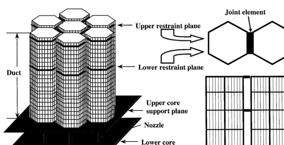
Fig.2
U p p e r r e s t r a i n t plane
L o w e r r e s t r a i n t plane
J o i n t e l e m e n t
U p p e r c o r e s u p p o r t plane Nozzle
L o w e r c o r e s u p p o r t plane
suggested that the magnitude of this negative reactivity feedback depended on the contact stiffness of the ACLP [ 10], which is thought to vary according to the number of contact faces [11]. This is why we think the simple beam model is inadequate for the analysis in the case of ATWS events.
To solve this problem, we have improved on the original shell model o f the original ARKAS code by developing ARKAS_cellule, a detailed shell model code which treats each sub-assembly by using many shell elements.
Model of ARKAS_celIule Code
Figure 2 shows the analysis model of the ARKAS_cellule code using a finite element method. To represent the non-linear stiffness arising from contact between neighboring surfaces, a fictitious element called a joint element is placed at each contact surface. This element also has the ability to represent frictional effects and to describe the state of partial, or angled, contact.
The core bowing analysis is a novel and difficult non-linear problem because it involves analyzing the non-linear iteration of hundreds of SAs separated by gaps which may open or close. To solve the non-linear equations, the ARKAS_cellule code adopts the Newton-Raphson method, in which a linear matrix equation representing the tangential stiffness characteristic of the nonlinear equations at each non-linear iteration step is solved repeatedly until convergence is obtained. Therefore, for obtaining a first running code, the key point is to find a method that reduces the computing time required for solving the linear matrix equation. In view of the fact that the nodal displacements of nodal points aside from the joint elements are unnecessary in reforming the linear matrix equation at each non-linear iteration step, a substructure method, which was introduced in making the original ARKAS code by one of us (Nakagawa), is also adopted for the ARKAS_cellule code. The new technique employing a substructure method is summarized below.
Let r = r n be an approximate solution for a global displacement vector; then an improved solution can be obtained by solving the following linear equation for Ar n :
KT(rn)Ar n :[f -e(rn)]
(1)where r n is the nth approximate solution for the global displacement vector (unknown value); K r (r) is the tangential matrix for global stiffness matrix on r ; f is the global load vector (known value), and P ( r ) is the global force vector required to deform the nodal points from their initial position to displacement r. The term "global" means the summation over all the finite elements in the model.
The tangential matrix K r (r) can be divided into two terms as
K r (r) = K c + K j (r) (2)
in which K c is the global stiffness (linear) matrix for all SAs and K j ( r ) is the global stiffness (non-linear) matrix for all joint elements. Substitution of Eq.(2) into Eq.(1) gives a linear equation to be solved.
[Kc + Kj(r)]~krn = [f -e(rn)]
(3)
The resulting displacement r "÷l (= r" + Ar") leads to a new set of linearized equations, which are solved again for Ar "÷~ . This procedure has to be repeated until the residual force vector, represented by the right-hand side of Eq.(3), converges on zero.
The nodal displacements of nodal points aside from the joint elements are unnecessary in reforming the linear matrix equation at each non-linear iteration step, because the non-linear terms in Eq.(3) ... such as Kj (r) ... can be obtained only from the displacements of the joint nodes that are common to joint elements. Therefore, in this new technique employing a substructure method, instead of directly solving Eq.(3), the following contracted equations consisting of the retained freedoms are solved:
-
(4)
t¢~T(r;)-: ~K(g) -[-~K; )[rn(e)
g=l
e=l
- ~ ~(g) _ I((g)[K(g)r~ ~l]~"(g) }+ ~ ~'(e)[pn(e) ]
--
I~ B~ " "L Bjr
"ffi Brj
"" J ~. j
g=l
e=l
? k ( F ; ) - - -- ~
{f)g)g=l
' --
"'Bjrl((g)[g(g)~lf/g)l-{~"(g)g=l
K B rjn(g)q- ~h(e)~;(e)]}e=l
(5)
(6)
Here, subscript j indicates values of retained freedoms and r those of reduced freedoms. The superscript g indicates values corresponding to SA(g). GB is the total number of SAs and Ej is the total number of joint elements. The matrix f,. (e) for k'(~> is obtained by eliminating the matrix coefficients corresponding to reduced freedoms from the stiffness matrix ..z
~,~j
joint element e. The vector h(~)[rn(~)]is the force required to deform joint element e from its initial position to rj displacement rs(") The matrices ~'(g) • - , . n ~ , g(g) ""R jr , to(g) and ~'(g) " ' B r r ' " ' n r j are the submatrices obtained by subdividing the stiffness matrix K~ g) for SA(g) into parts according to the "retained" and "reduced" freedoms. After the non-linear solution rj is obtained, the reduced freedoms can be calculated as
G
g=l
g=l
In solving the contracted matrix Eq.(4), the reduced size of the matrix makes it possible to reduce the calculation time to n e a r l y ( i / N ) 3 and the computer storage capacity to almost ( l / N ) 2 compared with directly calculating matrix Eq.(3). ( 1/N means the reduction ratio, namely the ratio of the number of unknowns in Eq.(4) to that in Eq.(3).)
E X P E R I M E N T A L DATA
In the UK, the AEA CHARDIS (Charge/Discharge) rig and NNC's CRUPER (Core Restraint Uni-Planar Experimental Rig) were the two main experimental facilities for investigating the behaviour of an array of interacting sub-assemblies. Since our object in this study is to use the CRUPER measured value as the validation data for the ARKAS_cellule code, the CRUPER experiments [12] are summarized below.
The purpose of the CRUPER experiments was to study the compaction sequence in arrays of hexagons. CRUPER was designed to simulate compaction of sub-assemblies at the above core restraint plane. In an operating reactor, this would
v w w v
occur after sub-assemblies subject to high bowing induced by radial thermal and flux gradients, i.e. those on the core/breeder boundary, move their tops radially outwards thereby reducing the gaps at the upper restraint plane and inducing their centers to move radially inwards.
To study compaction sequences in arrays of sub-assemblies, CRUPER represented a horizontal slice through a fast reactor core containing a restraint plane. The model represented 91 'sub-assemblies' (in five rings) of the UK commercial fast reactor (CDFR) core, which could be compacted by 30 peripheral rams (Figure 3). The CRUPER rig is shown in Figure 4. Each "subassembly" wrapper (duct) was just 600 mm long as shown in the left-hand portion of Figure 5. Flat-to-flat distance of the wrapper was 141.2 mm and the wall thickness was 3.2 mm. Load pads were attached at mid-height. These were shimmed to maintain small tolerances respecting the across-pads dimension. The gap between adjacent loads pads was nominally 1 mm when the rig was in a "relaxed" condition. All the 91 short wrappers were supported on a rigid base plate through a flexible mount comprising six rods fastened to a plate rigidly attached to each end of the wrapper and at their mid point fixed by a plate to a permanently mounted rigid central stalk (see the left-hand portion of Figure 5). The loads pads were "molycoated" giving a pad to pad friction coefficient of 0.15.
The first phase tests, applied as the validation data in this study, assessed the peripheral loads under a symmetrical compaction. In the tests, the 30 peripheral rams were moved in
Fig.4 General View of CRUPER
1 4 1 . 2
25.0 Young' s modulus = 2.0X 10⁵N/mm
2
Poisson's ratio=0.3
Rod Duct
Pad
S t a l k B a s e plate
3.2
600 ~ : -
shell e l e m e n t
e l e m e n t
Sliding interfaces having flexibility of 17ram/kN which was the measured value
Wrapper 9fCRUPER
W_r_apper Model of ARKAS cellule
Fig.5 Wrapper Configuration and Analysis Model
the radial direction toward the array center with seven intervals. For each interval of the seven compaction states, measurements were performed for the inter-wrapper gaps within the array and the loads and displacements for each ram. VALIDATION RESULTS
ARKAS_cellule Analysis
As shown in the left-hand portion of Figure 5, the CRUPER wrappers were supported by six flexing rods which gave an average combined flexibility of 17 mrn/kN, though individual wrappers showed variations up to + 50%. For ARKAS_cellule analysis, this value was translated into two suitable sliding stiffnesses at the top and bottom ends of the wrappers. Figure 5 shows the geometrical configuration of a wrapper of CRUPER and the calculation model of the ARKAS_cellule code. Young's modulus and Poisson's ratio for the ARKAS_cellule analysis are also shown in Fig.5.
Calculations were performed under the consideration of changing gap sizes between the peripheral wrappers and the array outer boundary faces to fit the measured displacements for each ram in each of the seven compactions.
Comparison of CRUPER and ARKAS_celIule Results
The comparative calculations of the contact pattern (i.e. residual gaps) and the loads on the outer wrapper (i.e. ram loads) were for a symmetrical compaction. Non-friction calculation is compared with experimental results below. The sensitivity to the pad friction coefficient is also briefly discussed.
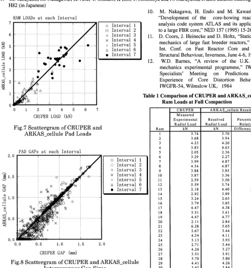
Ram loads during the compaction sequence are shown in Fig. 6 for the purpose of comparing the ARKAS_cellule analysis with the CRUPER results. The distributions of the measured and calculated ram loads are compared in the scattergram in Fig. 7. Ram loads show good agreement at low compaction states where the array is flexible. As multiface loading of the wrappers occurs and the stiffness of the array increases, ARKAS_cellule and CRUPER results diverge at a number of rams. Table 1 compares predicted ram loads with the measured ones, at Interval 7 (full compaction). The relative difference between the results is also tabulated. The mean relative difference is +8.2% with a standard deviation of 25.5%. Only odd ram position such as No.13 shows poor agreement, at other locations the maximum error is less than 40% at interval 7. Friction calculation using the friction coefficient of 0.15 shows that the mean relative difference is reduced to +3.2% with a standard deviation of 24.4%.
The distributions of the measured and calculated inter-wrapper gaps are compared in the scattergram in Fig. 8. All gaps are closed at Interval 7 (full compaction) for measured and calculated results. At Interval 3, the mismatch mean and standard deviation are -0.05 mm and 0.12 mm, respectively. Approximately 80% of the gaps are within the tolerance band of _+ 0.15
m m .
A comparison between the ARKAS_cellule analysis and the Phase 1 CRUPER experiments shows that the pattern of the build up of face loads and the reduction gap sizes during the compaction sequence can be simulated with good agreement.
SUMMARY AND C O N C L U S I O N
A new analytical method has been presented and the ARKAS_cellule code has been developed for determining the core distortion and mechanical behavior in fast breeder reactors (FBRs). A validation of the code is performed by means of a comparison with the experimental values obtained by an ex-reactor rig CRUPER. Through the validation presented here, it is clarified that the predictions made by ARKAS_cellule agree well with the measured loads and inter-wrapper gaps during the compaction sequence. Therefore, it is confirmed that the new model gives adequate results. The ARKAS_cellule code will be an effective tool for analyzing or evaluating the core mechanical behavior, and will be particularly useful for the analysis Of ATWS when distortions of pads have important effects.
A C K N O W L E D G E M E N T S
The authors are grateful to NNC and Mr. H. Ikeda of JAPCO, all of whom displayed great skill in using the NNC experimental results obtained by the CRUPER ex-reactor rig.
REFERENCES
1. IWGFR Specialists' Meeting on Predictions and Experience of Core Distortion Behaviour, IWGFR-54, Wilmslow UK, 1984
2. Verification and validation of LMFBR static core mechanics code Part I, IWGFR/75v. (1990), IAEA, Vienna. 3. RC Perrin, "CRAMP; Core restraint analysis and modeling programme," 5th, SMiRT, Berlin, 1979
O
•
I
:...::...~....;...:.
....
::::::
...
~...::...~: ....
....
....
:;::::
!"'?
....
i'"?"
!"'~'
I
I
Iilii ~-!''1'
!
n !
'
I
!
...
I
-
.
-
|
1===I
...
t
@,1
...
d
~=~
(N~t)peo~I
o
el,,,,(
o
_=
o
o
,m,,i
t=,
o
i.
~!
4. M. Nakagawa, "A three-dimensional finite element formulation for the static structural analysis of bowed reactor cores of LMFBR," SMiRT-6 E2/5 (1981)
5. M. Nakagawa, "ARKAS; A three-dimensional finite element program for core-wide mechanical analysis of liquid-metal fast reactor cores," Nucl. Technol., 75, 46 (1986).
6. M.Nakagawa,"Verification of core mechanical performance code ARKAS with IAEA benchmark problems," J.Nucl.Sci.Technol., 28[ 11], 973 (1991)
7 .
0
M. Nakagawa, "Verification of core mechanical performance code ARKAS with IAEA benchmark problems, (II)," J. Nucl. Sci. Technol., 3015], 389 (1993)
S. Tottori, I. Kawanaka, M. Nakagawa, K. Arie, K .Itho, T. Ohya, T. Motomiya and H. Adachi, "A study on fast reactor core mechanics by an ex-reactor test and comparisons with calculations," ICONE-4 (1996)
M. Tabayashi, M. Nakagawa., K. Arie, Y. Ohkubo, K Itho, T. Motomiya and N. Maruyama, JAERI autumn meeting 1997 H82 (in Japanese)
RAM LOADs at each Interval
7
. . .
5 . . . . . . .
.~ 4 : ... i .... i ; ! ... o • ::
~,~ 3 ~ . .... ! ... i ~: ...
~
2 ~ . . . i . . . :: .. . . ! . . . i .. . .1
o
::
i,
0 1 2 3 4 5 6 7
CRUPER LOAD (kN)
2 . 0
~ 1 . 5
v
<¢ ~D ~ 1 . 0
, ' - - - 4 , - " - 4
o
I
(13 ~ 0 . 5 <
0 . 0 ~
0 . 0
F i g . 7 S c a t t e r g r a m of C R U P E R a n d
A R K A S _ c e l l u l e P a d L o a d s
o I n t e r v a l 1
[] I n t e r v a l 2
o I n t e r v a l 3
x I n t e r v a l 4
+ I n t e r v a l 5
A I n t e r v a l 6
• I n t e r v a l 7
PAD GAPs a t e a c h I n t e r v a l
'
. . . ! . . . v ! . . . '
i x ::
i
% , ~ ~
...+.J . . . i . . .
- ~ - - - + ! -
× :
-- + i
0 . 5 1 . 0 1 . 5 2 . 0
o I n t e r v a l 1
[] I n t e r v a l 2
o I n t e r v a l 3
x I n t e r v a l 4
+ I n t e r v a l 5
A I n t e r v a l 6
• I n t e r v a l 7
CRUPER GAP (mm)
10. M. Nakagawa, H. End• and M. Kawashima,
"Development of the core-bowing reactivity
analysis code system ATLAS and its application to a large FBR core," NED 157 (1995) 15-26 11. D. Coors, J. Heinecke and D. Holtz, "Static core
mechanics of large fast breeder reactors," Proc. Int. Conf. on Fast Reactor Core and Fuel Structural Behaviour, Inverness, June 4-6, 1990
12. W.D. Barnes, "A review of the U.K. core
mechanics experimental programme," IWGFR
Specialists' Meeting on Predictions and
Experience of Core Distortion Behaviour,
IWGFR-54, Wilmslow UK, 1984
Fig.8 Scattergram of CRUPER and ARKAS_cellule
Inter'wrapper Gap Sizes
Table 1 Comparison of CRUPER and A R I ~ S _ c e l l u l e Ram Loads at Full Compaction
C R U P E R Measured Experimental
Radial Load
Ram kN
1 3 74
2 3 68
3 4 2 3
4 3 8 3
5 2 05
6 3 29
7 3 99
8 4 34
9 3 8 8
10 3 87
11 2 5 9
12 5 59
13 2 18
14 2.92
15 3.24
16 3.79
17 4.47
18 3.51
19 4.47
20 2.11
21 6.28
22 2.67
23 4.24
24 3.13
25 2.71
26 4 . 2 6 1
27 3.51 i
28 ~ 3.70
29 4.41
30 , 3.62
Mean Relative Difference(°~) Sample Standard Deviatuion(%)
A R K A S _ c e l l u l e Results
R e s o l v e d Percentage
Radial Load Relative
kN Difference(%)
3.70 -1.0
3.94 7.0
4.20 -0.6
4.63 21.0
2.36 15.2
2.27 -30.9
4.87 22.0
4.87 12.2
3.95 1.9
3.36 -13.1
3.50 35.2
3.74 -33.1
4.40 102.0
3.99 36.6
2.63 -18.8
3.85 1.6
4.38 -2.0
3.41 -2.9
4.77 6.6
2.84 34.5
5.05 -19.6
3.44 29.0
4.11 -3.0
3.93 25.6
3.44 26.9
3.27 -23.2
3.91 11.4
3.80 2.7
4.26 -3.3
3.84 6.0