University of Windsor University of Windsor
Scholarship at UWindsor
Scholarship at UWindsor
Electronic Theses and Dissertations Theses, Dissertations, and Major Papers
10-5-2017
Parametric Study of Film Formation and Curing Process for Film
Parametric Study of Film Formation and Curing Process for Film
Insert Molding
Insert Molding
Agostino Guerra
University of Windsor
Follow this and additional works at: https://scholar.uwindsor.ca/etd
Recommended Citation Recommended Citation
Guerra, Agostino, "Parametric Study of Film Formation and Curing Process for Film Insert Molding" (2017). Electronic Theses and Dissertations. 7265.
https://scholar.uwindsor.ca/etd/7265
This online database contains the full-text of PhD dissertations and Masters’ theses of University of Windsor students from 1954 forward. These documents are made available for personal study and research purposes only, in accordance with the Canadian Copyright Act and the Creative Commons license—CC BY-NC-ND (Attribution, Non-Commercial, No Derivative Works). Under this license, works must always be attributed to the copyright holder (original author), cannot be used for any commercial purposes, and may not be altered. Any other use would require the permission of the copyright holder. Students may inquire about withdrawing their dissertation and/or thesis from this database. For additional inquiries, please contact the repository administrator via email
Parametric Study of Film Formation and Curing Process for Film Insert Molding
By
Agostino Guerra
A Thesis
Submitted to the Faculty of Graduate Studies
through the Department of Mechanical, Automotive and Materials Engineering in Partial Fulfillment of the Requirements for
the Degree of Master of Applied Science
at the University of Windsor
Windsor, Ontario, Canada
2017
Parametric Study of Film Formation and Curing Process for Film Insert Molding
by
Agostino Guerra
APPROVED BY:
______________________________________________ R. Riahi
Department of Mechanical, Automotive and Materials Engineering
______________________________________________ J. Defoe
Department of Mechanical, Automotive and Materials Engineering
______________________________________________ J. Johrendt, Co-Advisor
Department of Mechanical, Automotive and Materials Engineering
______________________________________________ P. Henshaw, Advisor
Department of Civil and Environmental Engineering
iii
DECLARATION OF ORIGINALITY
I hereby certify that I am the sole author of this thesis and that no part of this thesis has been published or submitted for publication.
I certify that, to the best of my knowledge, my thesis does not infringe upon anyone’s copyright nor violate any proprietary rights and that any ideas, techniques, quotations, or any other material from the work of other people included in my thesis, published or otherwise, are fully acknowledged in accordance with the standard referencing practices. Furthermore, to the extent that I have included copyrighted material that surpasses the bounds of fair dealing within the meaning of the Canada Copyright Act, I certify that I have obtained a written permission from the copyright owner(s) to include such material(s) in my thesis and have included copies of such copyright clearances to my appendix.
iv ABSTRACT
The purpose of this work is to address a manufacturing problem related to the
technology of Film Insert Molding (FIM) for the production of vehicle interior
parts. The problem occurs in the first stages of the process during the production of
the film, prior to injection molding. The film was distorted in some cases. When
the distortion of the film was high, the film was not sticking to the mold properly,
showing a tendency to pop out. This led to pinching of the film in the mold which
caused two main failures: flashing of the resin and ripping of the film. A particular
emphasis was put toward the process stages of forming and UV curing, that were
identified through a root causes analysis, to induce major distortion of the shape of
the film. With the use of a laser scanner and analysis software: Geomagic control
X, it was possible to compare the shape of manufactured parts to the original CAD
model containing the nominal shape of the film. The analysis was based on two
full-factorial plans, one for forming of the film and one for UV curing it. Using
analysis of the variance (ANOVA) of the deviations, it was possible to detect the
influence of the factors on particular points of the surface of the film. It was found
that parameters related to forming: dwell time and temperature, had a significant
influence on the deviation of the film, the first accounting for about 50% of the
change in deviation. Once the forming parameters were set to achieve the lowest
deviation, parameters related to UV curing: UV oven conveyor speed and ink size,
v
DEDICATION
To my parents,
vi
ACKNOWLEDGEMENTS
This thesis marks an important milestone in my life, as it represents the end of a
five years journey I undertook in Torino, Italy. I am very grateful to my institution,
Politecnico di Torino, and Professor Giovanni Belingardi to have selected me for
the exchange program in Canada, where I worked on this thesis. The exchange
program has been an incredible opportunity for my personal and professional
growth. I am also grateful to FCA (Fiat Chrysler Automobiles) and in particular to
my Italian supervisor, Edoardo Rabino, as well as my Canadian supervisor,
Mohammed Malik. I would also like to acknowledge my advisors Nello Li Pira
and Rasheeda Danyaal to have contributed in the completion of the work. Nello’s
help has been amazing as he had to coordinate my work from Italy.
Thank you also to Marie Mills, whose attention to detail and ability to answer my
questions at a moment’s notice that has greatly sped up my work. She found
solutions to all the concerns I have had and was extremely helpful.
A big thank you goes to MacDermid, to Jeffrey McClintock and Michael Blake,
for their incredible support, that I found extremely useful in moments where I was
lost. The completion of this thesis was possible because of them, as they provided
valuable experiences in a professional environment.
I cannot forget to mention Mitchell Plastics, in particular Craig Newport, David
vii
many occasions with my questions, but they were always glad to help. I have
learned so many things working alongside with them.
An extremely warm thank you to Paul Henshaw, my academic advisor at the
University of Windsor, who has worked constantly with me throughout the entire
year. His involvement and his attention to details have allowed me to produce high
quality work and have led me through the steps of publication. Thank you to
Monica Ferraris, my academic advisor in Italy at Politecnico, who has contributed
to the completion of the thesis.
I want to thank my committee members at the University of Windsor, Jennifer
Johrendt, Jeff Defoe and Reza Riahi, whom have carefully reviewed my thesis and
have provided insightful recommendations.
Once again, thank you to Jennifer Johrendt, together with Mike Houston, as
academic supervisors of the program. You have helped choosing my academic
advisor for this thesis as well as the little concerns I have had throughout this year.
Un grandissimo ringraziamento va ai miei genitori, i quali mi hanno sempre
supportato in ogni istante dei ventitre anni della mia esistenza su questo pianeta.
Sono loro le persone a cui devo di piu, che hanno sempre voluto il meglio per me,
che mi hanno sempre incoraggiato a fare bene, a cercare di ottenere il meglio da
ogni situazione, hanno fatto sacrifici immensi per me, per permettermi di essere
qui oggi e non mi hanno mai fatto pesare una scelta che ho fatto, supportandola
con ogni loro forza. GRAZIE.
Back to the English speakers, I want to thank you, my roommates in Canada:
viii
friends, for all the moments shared together. I could not have wished for a better
group of people to live with. We have been assembled to work together perfectly,
with each of us contributing in their own way to the “family”. Our efficiency and
our way to manage the time, friends, study has been outstanding.
Thank you to Michael Mele, without your help, we would not have had this great
of an experience. You were wonderful to arrange everything for our house, and
such a great DJ!
I need to thank you some people from all over the globe I have met here in
Canada, which have become friends for life, in particular: Abby, Alan, Alessio,
Clara, Costanza, Chris, Donia, Hannah, Justus, Karoline, Karla, Katlina, Laura,
Marie, Mathias, Mehdi, Regina and Siddique. All of you guys have indirectly
contributed to my work, allowing me to have moments of leisure between
moments of study.
Thank you to all the members of the Exchange FC team(s), for Soccer and Bubble
Soccer, two great seasons with you guys!
Thank you to the Bull, and all of my friends who have ridden it, great memories.
Thank you to you, from which I still hear sometimes, although time and distance
do not help.
Thank you to all my Italian and Spanish friends, in particular Andrea, Giangy,
always present in my life, Federico and Silvio, classmates, Alberto and Ruben
from Madrid, Mauro, Peppone and Daniele as my Italian roommates, Carletto and
Maria, as my Bama family, Alessandra M., Kikka, Matteo, all of you guys for
ix
TABLE OF CONTENTS
DECLARATION OF ORIGINALITY ... iii
ABSTRACT ... iv
DEDICATION ...v
ACKNOWLEDGEMENTS ... vi
LIST OF TABLES ... xii
LIST OF FIGURES ... xiv
LIST OF ABBREVIATIONS ... xviii
CHAPTER 1 INTRODUCTION ...1
1.1 Vehicle Interiors Decoration – Display Size Trends. ...1
1.2 Objectives ...4
1.3 Scope ...4
CHAPTER 2 BACKGROUND ...6
2.1 Description of different types of bezels ...6
2.2 Optical requirements ...8
2.3 Physical requirements ...10
2.4 Design properties...12
2.5 Manufacturing of bezels ...13
2.5.1 In-Mold Labelling...15
2.6 Film Description ...24
2.7 Problem statement ...25
2.7.1 How to rank issues in the PFMEA and proper countermeasures ...28
2.8 Solution to the problem ...31
x
2.9 Approach to the study ...33
CHAPTER 3 METHODOLOGY ...34
3.1 Description of the approach used ...34
3.2 Measurement and analysis equipment...35
3.2.2 Analysis software ...38
3.3 Analysis ...38
3.3.1 Scan Data ...38
3.3.2 Export and import of data ...40
3.3.3 Align and overlap the scanned data to CAD ...40
3.3.4 3D comparison and color map ...41
3.4 Influential parameters ...42
3.5 Procedure ...44
CHAPTER 4 RESULTS AND DISCUSSION ...51
4.1 Results for forming...51
4.1.2 Result analysis for forming, influence of temperature and dwell time ...60
4.1.3 Result analysis for forming, Analysis of the means ...67
4.2 Results for UV curing ...71
4.2.2 Result analysis for UV curing, Influence of UV oven speed ...79
4.2.3 Result analysis for UV curing, Analysis of the means ...82
CHAPTER 5 CONCLUSIONS AND RECOMMENDATIONS ...86
5.1 Conclusions ...86
5.2 Implementation...87
5.3 Recommendations ...88
REFERENCES ...90
xi
Appendix A: PFMEA charts ...94
Appendix B: One-dimensional model for the determination of the dwell time ...96
Appendix C: Analysis of residuals for forming ...98
Appendix D: Boxplot and confidence interval bars of deviation for forming ...101
Appendix E: Analysis of residuals for UV curing ...104
Appendix F: Boxplot and confidence interval bars of deviation for UV curing ...107
xii
LIST OF TABLES
Table 1: Classification of gloss based on specular gloss units [8] ... 8
Table 2: Most common mechanical test standards. ... 10
Table 3: Common chemical test standards for coating resistance to fluids. ... 11
Table 4: Most common aging test standards. ... 12
Table 5: Forming results obtained pre-heating a film at different temperatures. ... 19
Table 6: Line of the PFMEA developed for the problem of pinching ... 30
Table 7: List of process parameters for forming and UV curing. ... 43
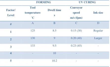
Table 8: Factor and relative levels used for DOE. ... 48
Table 9: Test matrix for forming ... 49
Table 10: Test matrix for UV curing ... 50
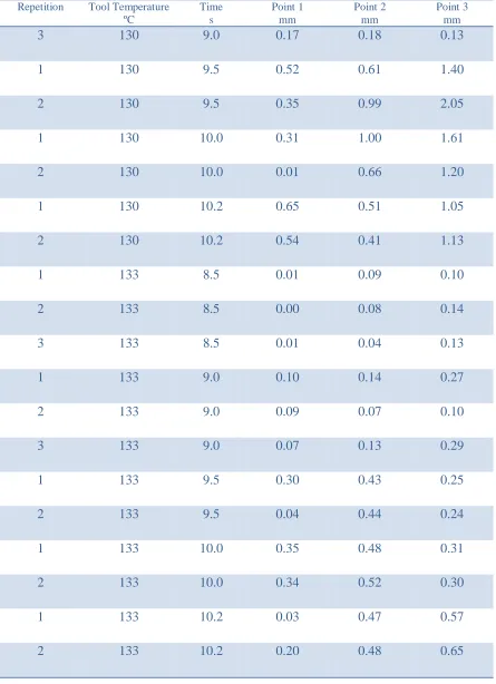
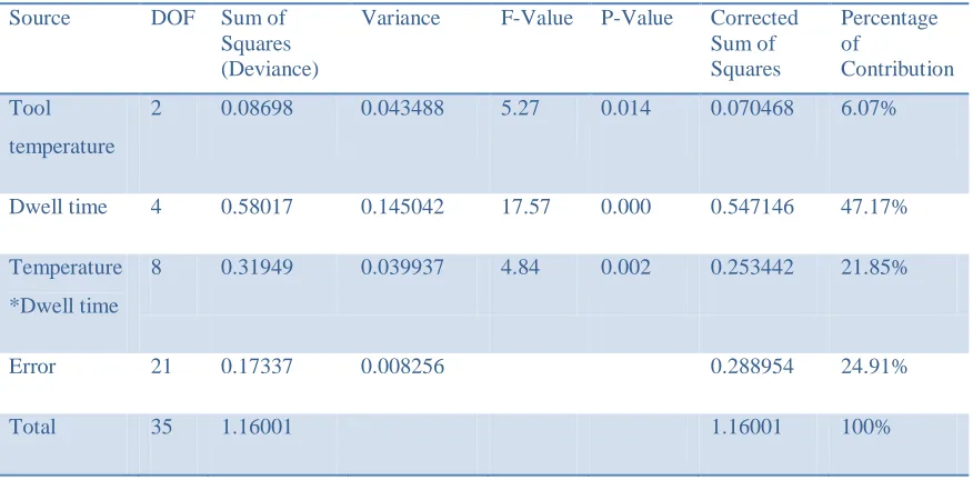
Table 11: Test results for forming for Point 1, Point 2 and Point 3 on the surface.53 Table 12: ANOVA table for forming (Point 1). ... 55
Table 13: ANOVA table for forming (Point 2). ... 57
Table 14: ANOVA table for forming (Point 3). ... 58
Table 15: Representation of the means for forming calculated for each test for each point. ... 67
Table 16: Test results for UV curing for Point 1, Point 2 and Point 3 on the surface. ... 72
Table 17: ANOVA table for UV curing (Point 1). ... 73
Table 18: ANOVA table for UV curing (Point 2). ... 75
xiii
Table 20: Mean deviations for UV curing for each test for each point. ... 82
Table 21: Updated PFMEA for pinching ... 88
xiv
LIST OF FIGURES
Figure 1: The forecasted increase of display number by size range [2] . ... 1
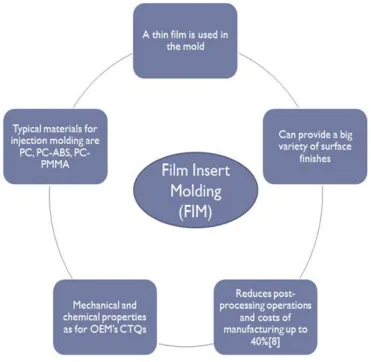
Figure 2: The main characteristics of FIM. ... 3
Figure 3: Modular bezel surrounding the display [5]. (Chrysler Pacifica) ... 6
Figure 4: Integrated bezel covering the entire surface of the display [6]. (Alfa Romeo Giulia) ... 7
Figure 5: Representation of total transmittance through a medium as the sum of diffused transmittance (haze) and parallel transmittance [9]. ... 9
Figure 6: Difference between a matte film and an anti-glare film [10]. ... 10
Figure 7: Chrysler Portal, EV of FCA @ CES 2017 Las Vegas [20]. ... 13
Figure 8: Process stages for FIM. ... 16
Figure 9: Representation of film composition. ... 25
Figure 10: Representation of flash of the resin. Some injected resin flowed out from the edges when it was still hot... 27
Figure 11: Representation of a ripped edge of the film, showing an improper contour. ... 28
Figure 12: Ishikawa diagram representing root causes identification for the pinching issue... 32
Figure 13: Map representing the steps taken in the thesis ... 35
xv
Figure 15: HMI of the laser scanner, showing list of possible settings for scanning
... 37
Figure 16: Map representing the procedure to follow to perform the analysis ... 38
Figure 17: Color map as outcome of the Software Geomagic Control X [41] ... 42
Figure 18: Relation between the Temperature of the film and the pre-heating (dwell) time for a specific location. ... 46
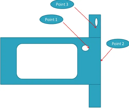
Figure 19: Sketch of the B surface of the part studied. Point 1, Point 2 and Point 3 are shown on the surface. ... 52
Figure 20: Percentages of contribution of factors and interaction in forming for the three points analyzed: a) Point 1, b) Point 2, and c) Point 3. ... 59
Figure 21: Mean of deviation of Point 1 for a) temperature change, and b) dwell time change. ... 61
Figure 22: Mean of deviation of Point 2 for a) temperature change, and b) dwell time change. ... 62
Figure 23: Mean of deviation of Point 3 for a) temperature change, and b) dwell time change. ... 64
Figure 24: Interaction map for the deviation of Point 1 (forming). ... 65
Figure 25: Interaction map for the deviation of Point 2 (forming). ... 65
Figure 26: Interaction map for the deviation of Point 3 (forming). ... 66
Figure 27: Graph of the deviation vs dwell time at a Temperature of 125˚C. ... 69
Figure 28: Graph of the deviation vs dwell time at a Temperature of 130˚C. ... 69
Figure 29: Graph of the deviation vs dwell time at a Temperature of 133˚C. ... 70
xvi
Figure 31: Mean of deviation of Point 1 for a) UV conveyor speed change, and b)
ink size change. ... 80
Figure 32: Interaction map for the deviation of Point 1 (UV curing). ... 81
Figure 33: Variation of the deviation of Point 1 vs Ink size for different Conveyor speed values. ... 83
Figure 34: Variation of the deviation of point 1 for different conveyor speed values with regular ink size used. ... 84
Figure 35: Variation of the deviation of point 1 for different conveyor speed values with larger ink size used. ... 84
Figure A-1: Ranking chart - Severity... 94
Figure A-2: Ranking chart - Detection ... 95
Figure A-3: Ranking chart – Occurrence ... 95
Figure B-1: Schematic of the pre-forming process ... 96
Figure C-1: Histogram of residuals for Point 1 (forming). ... 98
Figure C-2: Graph of the distribution of residuals vs observation order for Point 1 (forming). ... 98
Figure C-3: Histogram of residuals for Point 2 (forming). ... 99
Figure C-4: Graph of the distribution of residuals vs observation order for Point 2 (forming). ... 99
Figure C-5: Histogram of residuals for Point 3 (forming). ... 100
Figure C-6: Graph of the distribution of residuals vs observation order for Point 3 (forming). ... 100
xvii
Figure D-2: Boxplot of deviation of Point 2 vs Temperature ... 101
Figure D-3: Boxplot of deviation of Point 3 vs Temperature ... 102
Figure D-4: Confidence Interval bars for deviation of Point 1 vs Temperature ... 102
Figure D-5: Confidence Interval bars for deviation of Point 2 vs Temperature ... 103
Figure D-6: Confidence Interval bars for deviation of Point 3 vs Temperature ... 103
Figure E-1: Histogram of residuals for Point 1 (UV curing). ... 104
Figure E-2: Graph of the distribution of residuals vs observation order for Point 1 (UV curing). ... 104
Figure E-3: Histogram of residuals for Point 2 (UV curing). ... 105
Figure E-4: Graph of the distribution of residuals vs observation order for Point 2 (UV curing). ... 105
Figure E-5: Histogram of residuals for Point 3 (UV curing). ... 106
Figure E-6: Graph of the distribution of residuals vs observation order for Point 3 (UV curing). ... 106
Figure F-1: Boxplot of deviation of Point 1 vs UV conveyor speed. ... 107
Figure F-2: Confidence interval bars for the deviation of Point 1 versus UV
xviii
LIST OF ABBREVIATIONS
ABS – Acrylonitrile butadiene styrene
ANOVA – Analysis of Variance
CAGR – Compound annual growth rate
CSD – center stack display
CTQ – Critical to quality
DOE – Design of Experiments
DOF – Degrees of freedom
EV – Electric Vehicle
FCA – Fiat Chrysler Automobiles
FIM – Film Insert Molding
GU – Gloss Unit
HIC – High Impact Characteristic
HMI – Human machine interface
HPF – High Pressure Forming
HVAC – Heating, ventilation and air conditioning
IMD – In-mold Decoration
IML – In-mold Labelling
xix PC - Polycarbonate
PFMEA – Process Failure Modes Effect Analysis
PMMA – polymethyl methacrylate
1 CHAPTER 1
INTRODUCTION
1.1Vehicle Interiors Decoration – Display Size Trends.
Until the 1970s all displays for cars were just gauges lit by bulbs. Often, displays were minimized in dimensions because they had to leave enough room for other car parts such as HVAC air ducts, cables or mechanical elements [1]. Through the years, packaging has acquired more and more importance. Some parts of the vehicle have been minimized in shape, while there has been a fast improvement in the display technology that has led this component to have a predominant role in the center stack area of the panel. Nowadays, the HMI (Human Machine Interface) has acquired more and more importance as in today’s vehicles the interaction of drivers and passengers with electronic appliances has become extremely common. As shown in Figure 1, the size of the center stack display (CSD) is constantly increasing through the years. The graph shows a decreasing trend of the small size displays, and an increasing trend, highlighted with the yellow arrow, of medium size displays. The total number of displays is also expected to increase in the following years with a Compound Annual Growth rate (CAGR) of 6.7%1 [2] .
Figure 1: The forecasted increase of display number by size range [2] .
2
The three most important challenges for a display are three:
Captivating design;
Functionality for packaging;
Feasibility for manufacturing.
Displays are usually surrounded with bezels, which aim to provide decoration to the part. Automotive interior trim bezels are a source of differentiation for different car models. Their design has been investigated recently because they have become very popular.
Different aesthetic looks can be given to the part, using different technologies and manufacturing methods. There is a wide variety of techniques employed for the decoration of plastic parts for automotive interiors. Among them, film insert molding stands out. Film insert molding has become highly popular in recent years. Its purpose is to create a sense of value in customer perception for aesthetic surfaces. An exciting object from the visual point of view would increase the perceived quality and the brand reputation [3]. This technology replaces conventional methods of painting and coating injection molded parts, eliminating the necessity of post-processing operations and lowering the time and the costs of manufacturing. Film Insert Molding is able to provide different surface finishes on the part using a film. Behind the choice of a film there might be requirements from a mechanical, chemical and aesthetic point of view. A thin film is able to provide the plastic part with the required properties such as an increased durability or scratch resistance. Cost savings up to 40% over coated surfaces can be obtained [4]. This technique has shown great results for automobiles, electronic goods, medical devices and domestic appliances.
3
more stretching of the film and allows it to reach more convoluted shapes of the part. Figure 2 represents the main features of FIM technology.
Figure 2: The main characteristics of FIM.
4
pre-heating of the film (for a certain dwell time) and then the forming itself that takes place in a sealed forming tool, where high pressure is achieved. Also, the film has to be cured, because it has to achieve some mechanical and chemical properties as specified by different OEMs. OEMs requirements play a fundamental role, because the ultimate goal of the part is to pass these requirements to be sold to car manufacturers. If the film does not have a proper shape at the moment in which it has to be put in the mold, it means that some of the stages prior to injection molding were not well accomplished. This may result in the problem of pinching. The film may be pinched between the two mold cavities in the moment in which the mold closes for injection molding. If the film is pinched, injection molding cannot take place properly, causing defects such as flashing of the molten resin from the mold, and ripping of the film itself. This defect requires attention, as it may cause customer dissatisfaction, especially if the decoration of the part is not done properly.
1.2 Objectives
The main objective of this thesis is to minimize the occurrence of an high-rated problem of the IML process: pinching. The work aims at reducing the Risk Priority Number (RPN) of the failure mode in the Process Failure Mode Effect Analysis (PFMEA) through improvement of the process parameters for the manufacturing of the film to reduce occurrence.
1.3Scope
5
process are properly set in the shortest time possible. The process parameters have to be set properly in this phase in order to be ready to produce high quality parts in the actual production process. This is also a critical phase for the occurrence and detection of defects, that have to be properly identified and addressed in the shortest time possible. In this thesis, the main variables of the process will be identified, focusing on the ones that mainly influence the shape and the distortion of the part, as to prevent the occurrence of the pinching defects. The main focus will be toward the processes of forming and UV curing. A parametric study was performed, varying the parameters among certain values:
There will be two major outcomes of the thesis:
1. the parameters that mainly influence the process and the deviation of the part, and their percentages of contribution.
2. the set of parameter values that minimize the deviation, so as to assist the plastic manufacturer in the determination of parameters values for the actual production process.
6 CHAPTER 2
BACKGROUND
2.1Description of different types of bezels
As a first important step, it is fundamental to distinguish between two different types of bezels:
Modular Integrated
The first one works as a frame for the display. Its shape surrounds the display in order to provide a decorative function. In this case the lens of the display is not part of the bezel but it constitutes a different part. It is possible to notice a little step between the surface of the lens and the surface of the bezel as a tactile sensation as shown in Figure 3 On the other hand, an integrated display is a display that has been integrated with the rest of the dashboard. The plastic bezel constitutes the frame that surrounds the display and it also includes a lens, underneath which the display is applied. With this solution, there is a seamless feeling to the surface, as there is no distinction between the vehicle’s interior trim and the display. An example of integrated bezel is shown in Figure 4.
7
Figure 4: Integrated bezel covering the entire surface of the display [6]. (Alfa Romeo Giulia)
At this point it is also fundamental to distinguish between the functions of these different types of display. The bezel has to be:
Decorative Functional
Decoration provides to the part a certain aesthetic value, which increases perceived value and brand reputation [7]. Decoration is usually achieved by both types of displays. It is fundamental as far as vehicle interiors are concerned. Tolerances in the production process have to be as tight as possible, because graphics have to be positioned in the right position as they were designed. With an integrated display, since the lens of the display becomes part of the bezel, it has to provide another characteristic: functionality. This means that the bezel has to meet some requirements as specified by OEMs in order to meet customers’ requirements.
8
2.2Optical requirements
Visibility is one of the first requirements: The lens has to have optical characteristics best suited to conditions inside the vehicle. The lens has to provide a certain transmittance so that the radiant energy coming out from the display reaches the users’ eyes. Transmittance basically defines the passage of electromagnetic radiation though a medium. It is the ratio of transmitted radiant power to incident radiant power. It has to be as high as possible and commonly reaches 90%.
On the other hand, reflectance should be lowered as much as possible. It is an unwanted effect that sunlight, or light coming from other sources, is reflected directly in the drivers’ eyes. Reflectance is usually very low. Its value should be kept below 10%. In some cases, it can be lowered below 5% with an Anti-Glare lens.
A lens can present a matte or a glossy surface. Gloss is a measure of specular reflection. It is measured by quantifying the amount of light reflected by a surface. It is measured in gloss units (GU). Table 1 aims at quantifying the specular gloss for an angle of 60˚. A matte surface helps in reducing the reflection. In order to have an Anti-Glare lens, the Gloss Unit has to be kept low.
Table 1: Classification of gloss based on specular gloss units [8]
Gloss range with 60˚ Gloss meter Value
Low Gloss <10 GU
Semi Gloss 10 to 70 GU
High Gloss >70 GU
9
transmission medium. A part of this light will be diffused, another part transmitted without change in direction, defined as parallel transmittance.
A low value of haze is usually required in order to have good visibility of the display. The parallel transmittance is a measure of the display clarity. Contrary to haze, its value has to be as high as possible.
Figure 5: Representation of total transmittance through a medium as the sum of diffused transmittance (haze) and parallel transmittance [9].
10
Figure 6: Difference between a matte film and an anti-glare film [10].
2.3Physical requirements
The lens has to provide sufficient characteristics from the mechanical point of view as well as from the chemical point of view. The durability of the part has to be guaranteed. Some of the most important tests that the lens has to withstand are shown in Table 2:
Table 2: Most common mechanical test standards.
Test name Purpose
Adhesion
Fiat 50457 [11]
It is a test method to assess the resistance of coatings to separation from substrates. It measures the property of adhesion of the coating to the substrate.
Resistance to wear
Fiat 50488/02 [12]
It is used to determine the fretting resistance of decorative coatings.
Five Finger Test
LP-463DD-18-01
[13]
It is used to determine the scratch and the mar resistance of coatings using a linearly-oriented, one pass, multi-fingered scratching device.
11
Table 3: Common chemical test standards for coating resistance to fluids.
Test name Global commercial fluids
Armor All
LP-463PB-31-01 B [14]
“Armor All” products [spot test]
Windex glass cleaner
LP-463PB-31-01 B [14]
“Windex glass cleaner” products [spot test]
Suntan Lotion SPF 50
LP-463PB-31-01 D [14]
“Suntan Lotion SPF 50” products [Suntan Lotion test]
Royal Pine solid air
freshner
LP-463PB-31-01 K [14]
“Royal Pine solid air” products [Air freshener resistance test]
Acid .1 N H2S04
LP-463PB-31-01 H [14]
“H2S04” products [Acid or Alkali spot test]
Alkali .1 NaOH
LP-463PB-31-01 H [14]
“NaOH” products [Acid or Alkali spot test]
Resistance to Ethyl
alcohol
FIAT 9.55842/01 [15]
“Ethyl alcohol” products
12
Table 4: Most common aging test standards.
Test Purpose
Natural weathering
ASTM G24 – ASTM
D3359 B [16]
Evaluate the resistance of nonmetallic materials to solar radiation filtered through glass in passively ventilated and non-vented enclosures.
Accelerated aging
SAE J2412 [17]
Specify the operating procedures for a controlled irradiance, xenon arc apparatus for the accelerated exposure of various automotive trim components Humidity
FIAT 50184/B [18]
Simulate effects of the same nature as those encountered during service on vehicle under various environmental conditions. In particular: Humidity
Thermocycle
FIAT 50184 [18]
Simulate effects of the same nature as those encountered during service on vehicle under various environmental conditions. In particular: Temperature
Heat Age
LP-463LB-13-01 [19]
Provide an accelerated method of testing the resistance of materials to heat aging
2.4Design properties
13
Figure 7: Chrysler Portal, EV of FCA @ CES 2017 Las Vegas [20].
Some limitations for manufacturing of FIM parts have to be respected. There are some limitations on the shape of the part, because current tooling does not allow the part to be bigger than certain dimensions. Also the depth of forming is one of the major concerns. In the design phase the radii of the part should not be smaller than a value that depends on the characteristics of the film, in particular, its thickness.
2.5Manufacturing of bezels
Bezels are usually made of plastic, and their decoration is commonly accomplished by the process of injection molding followed by painting [21]. Various surface finishes can be achieved with the processes of painting and coating. Painting allows the required decoration; coatings are applied on the part to increase its mechanical and chemical properties, providing strength and cohesion.
14
different coatings would provide different appearances to the surfaces. Joining the two parts together can be challenging and cost demanding. Furthermore, painting defects such as orange peel, sag and paint spits could give a poor surface appearance. A solution could be to injection mold only one piece and treat parts of it differently for the different surface finishes required. Disadvantages of the second approach include the requirement of a long supply chain and labor-intensive steps [22]. Sun [23] has pointed out the possibility of manufacturing the part through a multi-shot operation, co-molding two different materials in the same part. This can help to ease post-treatments, requiring less labor-intesive steps, because the different materials would react differently with the coatings that will be applied. The application of the process depends on the material availability and feasibility with different coatings. The idea of injection molding two different materials to make the same plastic part has also been supported by Scarabelli et al. [24] who found a very versatile method to reduce post treatment processes and associated costs in order to have various colors on a plastic surface.
15
Kitamura et al. [27] developed a way to decorate plastic parts with a particular injection molding process followed by a decoration molding to achieve the desired surface finish. The method is called In-Mold Coat Molding, where a decorative film is injected on top of a plastic part. Common problems described in the patent, such as the necessity to have the mold at two different temperatures during the first injection molding and the successive decorative molding, have been solved by employing individual cavity molds for the parts of the process. Using two mold cavities in this way the issue of heating up the mold cavity to a higher temperature is overcome.
2.5.1 In-Mold Labelling
The process of In-Mold Labelling (IML) consists of different phases. The process is slightly longer than IMD, because the film has to go through several steps before it is actually put in place in the mold. One of these operations is film forming which allows the achievement of more convoluted shapes and geometries compared to IMD. The film used for IML is usually thicker than the one used for IMD. The required number of operations for IML, before the actual injection molding, can vary from 3 to 4, depending on the requirements of the film. The process in total has five different operations [28]:
Screen printing
Forming
UV curing
Trimming
Injection Molding
16
Figure 8: Process stages for FIM.
Each of these operations provides the film with an added value and allows the possibility of customizing the part, depending on the priorities of the customer. Usually film suppliers are different from mold suppliers, so cooperation between all members of the supply chain is needed to obtain the best performance.
The process of Film Insert Molding starts when hard-coated clear polymeric sheets are screen printed.
2.5.1.1 Screen Printing
17
this phase of the process. A light sensitive layer is poured onto the screen fabric, exposed with the print image. On the screen some ink-permeable and ink-impermeable areas are created so that the ink only sticks to the section where it is needed. The printing ink needs to have some important characteristics such as flexibility and adherence to the film surface. The ink on the film has also to be resistant in the sense that it has to stick to the part since it will go through all the following stages of the process, when it will undergo thermal stress and high shear forces.
2.5.1.2 Forming
Forming is a very delicate part of the process through which the polymeric sheet acquires a 3D shape. Forming has to guarantee that the film has the desired shape within tight tolerances. An excellent formed film would result in an optimal shape that matches with the tools used for subsequent operations. Poor forming instead would cause a non-optimal shape of the film that will not match with the mold, resulting in scrap. The number of scraps in the film insert molding process is then related to the forming process. The forming process changes depending on the requirements of the film. The temperature is a key factor and can be set to the process used. There are two main techniques utilized to form the film. The most common one is thermoforming that involves heating the film to a very high temperature, above the polymer’s glass transition temperature. The film comes either in a roll or in sheet form, depending on the type of forming machine. It is heated above its glass transition temperature through the use of radiant heaters [29]. Thermoforming is suitable when higher stretching of the film is required [30]. It means that forming precision is higher for thermoforming than for high pressure forming, especially when the part has a very convoluted 3D shape. Thermoforming is not recommended when the decorations on the part have to be in a specific area with a tight tolerance, which is often the case for cars’ interior trim. Thermoforming is often not appropriate for matte and textured films because it makes matte films glossy and damages textures.
18
Ceramic heaters are both above and below the polymeric sheet, but they are kept at a certain distance. The temperature of each one of these heaters can be set according to the needs: if a part or one side of the film needs to be stretched more because a more convoluted shape is required, then that specific part of the sheet can be heated more and has to reach a higher temperature. Preheating assumes a fundamental role in the process of forming because it not only has to heat up the sheet, but it also has to provide the right amount of heat to specific parts of the film. Once the sheet is warmed up to a temperature higher than the glass transition temperature of the polymer, it softens. In order to have an idea of the temperature involved in the process, a polycarbonate (PC) sheet is usually heated to about 190˚C (the glass transition temperature of polycarbonate is about 147˚C [31] ) in order to be formed properly. If the temperature is too low, cracking can occur, if the temperature is too high, the film may be damaged [32].
19
Table 5: Forming results obtained pre-heating a film at different temperatures.
Surface
temperature of
the film
Forming results [32]
150˚C
Film distorted, base surface not flat, inaccurate removal from mold, cracking detectable in the material (stretch marks). Film material not sufficiently flexibilized
176 ˚C
Reduction in stresses, swelling of the base surface, improved removal from mold, significant reduction in cracking. Tendency towards improvement
192 ˚C Virtually stress free dial, very good flatness, accurate removal from the mold, structure undamaged. Good value found.
210 ˚C
Virtually stress free dial, very good flatness after separation, slight blistering, matt-black film content looks “flinty” (glossing). Forming process too hot
20
windows are kept in the designed positions with a better accuracy. This happens if the temperature of the film after pre-heating is kept low. In cars’ interiors tolerances are a fundamental parameter. The machine most commonly used to perform this type of forming is made by Niebling GmbH (Penzberg, Germany), which allows the fabrication of large components for vehicle interiors with high accuracy.
The forming process cannot cause excessive stretching of the film, so that decorations are kept in the programmed positions. Tolerances in the order of 0.3 mm are ensured and cycle times vary between 10-15 s [30].
The main advantages of using HPF are listed below:
Low stretching
Tight tolerances
Retention of surface finish (glossy, textured or matte)
Suitable for large and thick parts (up to 12 mm thick)
Good capability to form chemically and mechanically resistant films.
2.5.1.3 UV curing
21
determines the duration of UV rays the sheet receives. An higher speed gives a lower dose, a lower speed, intuitively cures the part more. Film specifications very often require that the film is not heated above a certain temperature in the oven in order to avoid warpage of the part. Of course, the longer the film is physically in the oven, the higher the temperature it reaches. The UV oven is a very sensitive part of the process because it may induce warpage and a distortion of the part, resulting in scraps.
2.5.1.4 Trimming
The formed sheet of polymeric material is then at a stage in which the unnecessary parts have to be trimmed out. So the sheet is put in a trimming die and cut. Unnecessary parts of the sheet are thrown away and the decorated, formed and cured fil is extracted from the die. The dimensions of the formed sheet have to match the dimensions of the die in order to perform cutting properly. Moreover, it is fundamental to ensure that the tool works properly and it is sharp enough. Replacement of the trimming tool after a certain number of pieces is necessary in order to keep the trimming tool working properly. The cutting area has to be kept free of debris in order to avoid inducing any possible distortion in the foil.
2.5.1.5 Injection Molding
The film is usually placed in the injection molding machine by an automatic end-of-arm tool. Again, the film has to be kept free of distortion until the moment in which it is put in the mold. At this stage it is fundamental that no dirt and no dust are present on the film and on the surface of the mold so as to avoid contamination. The A surface of the film (the front part) will be squeezed against one side of the mold, so any debris would result in a defect.
22
parameters and make sure the process proceeds smoothly. The cycle is usually made up of the following stages [4]:
1. The film is inserted in the machine by an end of arm tool;
2. The mold is closed;
3. Molten polymeric material is injected in the cavity by the injection unit;
4. Holding pressure is applied if needed;
5. Cooling time is provided to the part;
6. The injection unit moves back, it gets filled again with new material and gets ready for the following cycle;
7. The mold opens;
8. The component is ejected and the cycle starts over.
The time varies a lot depending on the part to be produced. Factors influencing the cycle time are the part geometry (thickness), the material and the tool [4].
23
and melt temperature, considering a film made of polycarbonate, the retardation-induced temperature is observed to increase as the thickness of the film increases [33]. This phenomenon is of high interest for the problem of warping. Warping may occur if a non-uniform heat distribution takes place between the mold and the plastic part. Warping of film-insert molded parts increases as the thickness of the film increases and decreases with the increase of the substrate thickness [34].
Another important aspect related to the injection molding stage is that it is fundamental that the film is held in the mold in a stable position. Sometimes the geometry of the part is sufficient so that the film is able to hold itself in a stable position throughout the molding process without tilting. In some other cases some techniques to keep the film in the right position can be utilized. The most common and known techniques used are air pins, vacuum and electrostatic charges. Air pins are pins coming out from one side of the mold cavity, aimed at holding the film in place. They are basically applied on the B side of the film, pushing the A side towards the mold cavity. Air pins should be located properly in the mold so that a good result is achievable. Vacuum is another commonly used technique. It mainly consists of holes in the mold cavity from which a negative pressure is generated. Vacuum holes suck the A surface of the film toward the mold cavity. The vacuum has to be applied carefully, especially if the film is thin or soft. An excessive vacuum pressure could cause the film to be sucked in the holes, resulting in deformation of the A surface. A trade off between holding the film properly and avoiding the generation of surface defects has to be found. Electrostatic charges are also used as a common method to hold the film in place. A static charge is applied on the film and so it will be attracted by the metal surface of the mold. It is important in this case to consider the material of the film. It has to be able to accept and maintain a static charge for the entire time in which the film is kept in the injection molding tool [35].
24
2.6Film Description
Goto et al. [36] worked to provide a good film for FIM. The purpose was to avoid cracks generated in a deep drawn part or at a small curvature radius part, while maintaining a good moldability and hardness. The film was made of three or four layers. The first was a hard coat. The hard coat layer thickness is between 2 and 20 μm in order to let the part have a good level of hardness. If the thickness of the layer increases the hardness of the film increases as well, especially when the film is UV cured. A too thick hard coat layer would instead be the cause of a bad moldability of the film, because it cannot be stretched enough. The second part is the film itself. This is usually made of the materials above-mentioned. The thickness of the film changes according to the part that has to be manufactured. It usually ranges between 10 and 300 µm but it can also be thicker. A thinner film is usually used when a large stretching of the film is not required (and often the film is not even pre-formed before injection molding). If the film had a thickness lower than 10 µm, it would not be able to resist injection molding and would break easily. The third part is a binder layer. It is not always required as its function is to make the ink layer stick to the film layer. If the ink itself allows for a better adhesion with the film, the binder layer is not needed. The fourth part is Ink layer. Its thickness is usually lower than 20 µm. The ink layer is generally applied on the first stage of the production process through the process of Screen Printing. Ink gives aesthetical properties and it is the first customizable operation that differentiates the products.
25
The film has to be tested and to pass specific requirements for its function. OEMs usually provide a list of specifications that the film has to pass, as shown in Table 2. Once approved, the film can start to be used in production. The necessity of approval for the film has lead the film manufactures to make their products as versatile as possible, so that it does not have to be tested numerous times.
2.7Problem statement
It is often a common problem in the pre-production phase that the shape of the film is improper, after the curing stage of the process. An improper shape of the film, showing distortion or improper dimensions, causes problems for the subsequent stages of the process. The cured film is supposed to be put in the trim die mold and then eventually in the injection molding tool. Some sections of the part may fit in the mold, where the surface is flat, whereas some others, especially where a certain curvature has to be guaranteed, have a tendency to pop out. If the shape of the film is not the expected one, problems related to pinching may occur. Pinching takes place when the film is put in the mold. Here it pops out from its original, designated position and moves towards the edges
Hard coat 2-20µm (preferably 4-10µm)
F
IL
M
Film 10-300µm (preferably 25-250µm)
Ink layer <20 µm
Resin 3-4 mm
S
U
BS
T
RA
T
E
26
of the mold cavity. When the two mold cavities close, prior to injection molding, the film may remain trapped between the edges of the mold cavities. Pinching of the film in the mold has basically two potential failure modes: flashing and ripping.
The first type of failure is flashing of resin. It takes place because if the film is trapped between the two mold cavities, the mold is not properly sealed. When the resin is injected, it is at a very high temperature and so it has low viscosity. The molten resin is free to move in the mold cavity, but would be free to move also outside the mold tool if it finds an opening. The pinched foil at the edge of the cavity provides such an opening. When the resin temperature cools down, it solidifies, remaining stuck to the side of the part (Figure 10). Having a piece of plastic coming out from the part is not desired mainly for three main reasons:
There is a waste of resin
If some resin escaped from the boundaries of the part, it means that there is less
resin within the boundaries. The final part might present some further defects related to this, such as holes or deformation.
The resin flashed has to be removed, adding a further step to the process. The
27
Figure 10: Representation of flash of the resin. Some injected resin flowed out from the edges when it was still hot.
28
Figure 11: Representation of a ripped edge of the film, showing an improper contour.
The film used for this analysis is Xtraform High Gloss provided by MacDermid Autotype (Ferndale, Michigan). It is a Polycarbonate film with thickness 380µm. The film is regarded as thick compared to other films used for IML process. The reason is that it can stretch more which allows it to reach more convoluted shapes. The film is made of an XtraForm Coating of 6 µm thickness constituting the first layer, the hard coat; the second layer is a PC layer 380 µm thick. The third layer is applied onto the part through the process of Screen Printing. Black ink is applied.
2.7.1 How to rank issues in the PFMEA and proper countermeasures
29
which are Severity, Occurrence and Detection. The product of these three indicators is defined as RPN, Risk Priority Number. The RPN is the main indicator to which one has to refer to when dealing with top rated issues. An RPN of 200 is generally considered a high value and it means that the priority to solve the issue is high. Other cases of high priority concern the case of a low RPN but single category values of 9 or 10. The issue analyzed in this thesis falls in the first category, where an RPN of 200 or higher is found. The RPN is often seen as an arbitrary value that comes out as a result of arbitrary numbers assigned to each category. Appendix A shows the chart that was used to attribute the grades to the categories of Severity, Detection and Occurrence [37].
Severity is generally ranked when a potential failure mode results in a final customer or manufacturing assembly defect. If both occur at the same time, the higher between the two values has to be used. A high value of 10 means that the failure mode affects the safe vehicle operation and the failure could occur without warning. In this work, a moderate value of 5 was chosen, as the item is operable but at a reduced level of performance and would see the customer dissatisfied. It means that 100% of the product may have to be reworked to fix the issue [37].
Occurrence is strictly related to the probability of failure. The failure mode has to be related to the frequency with which it occurs. The main categories for Occurrence are persistent failures, frequent failures, moderate, low and remote failures. For the issue in this thesis a value of 5 has been chosen, falling in occasional failures. A value of 5 implies that the there is more than 1 and less than 5 failures per thousand items [37].
30
Table 6: Line of the PFMEA developed for the problem of pinching
31
2.8 Solution to the problem
Countermeasures are proposed in order to lower the new RPN. The countermeasures proposed are:
Use of laser scanning to improve “Detection”.
Improvement of forming and UV curing process parameters to improve “Occurrence”.
The last part of Table 6 has been left blank because it will be filled in only once the results from the analysis re implemented and then it will be possible to quantify the effects. At that point, new values for Severity, Detection and Occurrence will be put in the table and the RPN will be re-evaluated.
2.8.1 Root causes identification
32
Figure 12: Ishikawa diagram representing root causes identification for the pinching issue.
Some causes have been already discarded because previous studies, specific for this part have been carried out and have shown that pinching is not related to them. Specifically the relaxation of the material after high pressure forming has been taken into consideration by the tool supplier when the tools where designed. Differences in the size of forming, trimming and injection molding tool have been accounted for by the tool supplier for the specific film used, so this has been discarded as the possible cause of pinching.
33
𝑇ℎ𝑖𝑐𝑘𝑛𝑒𝑠𝑠 𝑜𝑓 𝑓𝑜𝑟𝑚𝑒𝑑 𝑓𝑖𝑙𝑚
𝑂𝑟𝑖𝑔𝑖𝑛𝑎𝑙 𝑓𝑖𝑙𝑚 𝑡ℎ𝑖𝑐𝑘𝑛𝑒𝑠𝑠 𝑥 100 = % 𝑜𝑓 𝑜𝑟𝑖𝑔𝑖𝑛𝑎𝑙 𝑡ℎ𝑖𝑐𝑘𝑛𝑒𝑠𝑠 (1)
Film specifications claim that the film may be drawn until it reaches up to 50% of its original thickness (50% draw ratio).
Different cross sections, in different areas of the part have been considered. Where the film has a more flat shape, the draw ratio was found to be around 90%, whereas in the curved area, the draw ratio turned out to be above 65%, showing that thinning of the film is likely not an issue in the process, because it remains above the minimum draw ratio.
Debris are considered not to be an issue for the shape of the part, because the type of defect is not related to contamination.
2.9 Approach to the study
34 CHAPTER 3
METHODOLOGY
3.1 Description of the approach used
35
Figure 13: Map representing the steps taken in the thesis
3.2 Measurement and analysis equipment
3.2.1 Laser scanning
36
Figure 14: Next Engine Desktop 3D scanner [39]
37
Figure 15: HMI of the laser scanner, showing list of possible settings for scanning
The HMI of the scanner is very intuitive and not complex. From Figure 15 it is possible to see how to set the parameters that influence the scanning.
38
3.2.2 Analysis software
The analysis software that was used to build the mesh was “Geomagic control X” (Morrisville, North Carolina). The program enables the user to reconstruct the mesh starting from the points cloud. It is possible to import into the program the points cloud of the scanned part in its .xyz extension and a CAD file with a .stp extension. The program also allows the user to compare the shape of the scanned part with the CAD file, showing a measure of the deviation. The most valuable outputs of the program were:
A color map showing the average deviation of sections of the scanned part from
the original CAD model
The deviation of every single point detected on the surface from the CAD model A histogram with the distribution of points around the nominal value
3.3 Analysis
The work-flow for arriving at deviation values was as shown in Figure 16:
Figure 16: Map representing the procedure to follow to perform the analysis
3.3.1 Scan Data
39
use of an adjustable support. In this case, roughly three quarters of the part fit in the view of the scanner, because the field of view was 25.4 x 33 cm.
The film to be analyzed consists of a flat part and a curved one. The left-hand side of the part is assumed to be of the proper dimensions, since pinching and tearing did not occur in that section of the part, and thinning of the film is not an issue, because it does not stretch. On the contrary, the section of the part that generates more interest is the right-hand side, in which a curvature and some holes - with the purpose of holding the part in place in the mold - are present. This leads to analyzing the right-hand side of the part as it is the section of major interest. Details of the part are given in Section 4.1
The part is a thin film of thickness 380 μm with a black and glossy surface. A 360˚ scanning of the part was not possible to be performed because the part would need to be hanged and rotated while the scanner acquired the shape. The nature of the part –its material and geometry- would cause it to swing and the final representation viewed by the scanner would be distorted. To scan the part, it was fundamental that the film remained steady during the whole scanning process. Any form of distortion of the part had to be avoided. In order to minimize this factor, the part was put with its B surface (back of the film) faced upwards.
40
The thickness of the part is not going to be acquired by the scanner. Only one
surface is scanned (B surface), so the result will show just the curvature and the other two dimensions.
The thickness of the sprayed layer is only 5 μm assumed to be evenly distributed
on the surface, so no differences will be shown.
The accuracy of the scanner is 100 μm, much more coarse than the thickness of
the sprayed layer.
For these reasons, the use of the spray is not considered to be a problem for the analysis.
3.3.2 Export and import of data
The process of exporting the scanned data from the scanner program was straight forward. The cloud of points was exported as an .xyz file in order to be an input to the analysis software.
The process of importing the files in Geomagic control X was also very simple and straight forward. First, the scanned file was imported, then the CAD file. The scanned file is usually stored as unit-less data. It was important to define the unit of measure: millimeters or inches. For easy import, the CAD file has to have a .stp (Standard for Exchange of Product) extension.
3.3.3 Align and overlap the scanned data to CAD
41
Once the first alignment was performed, this could be improved with the command ‘Best fit Alignment’. Again, the program itself worked on improving the alignment between the two files in order to obtain more accurate results, keeping as a reference the ‘Transform Alignment’ that the user had manually done. The command ‘Best alignment’ was needed in order to minimize variability in aligning the shapes, to minimize the effect of human errors.
3.3.4 3D comparison and color map
Once the alignment has been performed correctly, it was then possible to compare the two parts though a 3D comparison. The kind of analysis that could be performed was an analysis of the shape of the two parts, based on the B surface.
The sampling ratio was set to 100% so that all the points scanned were actually compared to the CAD model. The value of the sampling ratio could be decreased in case the density of points of the scan was too high and the analysis needed to be speeded up. In the section ‘Method’ the ‘Shape’ option was selected because the surface of the part was the one of main interest.
42
Figure 17: Color map as outcome of the Software Geomagic Control X [41]
It was possible to define a green interval which is the acceptable deviation. As long as the scanned file is within this deviation, its shape is within tolerance. Of course, the purpose of this study was to minimize the blue and the red areas, which respectively correspond to under tolerance and over tolerance. An excessive deviation would result in an incorrect shape of the part and so it would not fit in the mold properly. Figure 17 shows the color map, showing the average deviation of each specific area. It was possible to analyze the deviation of every single point in the figure.
3.4 Influential parameters
43
Table 7: List of process parameters for forming and UV curing.
Parameter [Unit of
measure] Current value
Estimated
optimal value Status
Upper right
heater ˚C 300 300 FIXED
Upper left
heater ˚C 370 370 FIXED
Lower right
blue ˚C 300 300 FIXED
Lower left
yellow ˚C 340 340 FIXED
Air heater ˚C 300 300 FIXED
Form tool
temperature ˚C 130 125-133 FIXED
High pressure
bar 75 75 FIXED
High pressure
max bar 80 80 FIXED
Preheating
(dwell) time s 10 8.5-10.2 VARIABLE
High pressure
time s 7 7-10 VARIABLE
Outlet time s 10 8-10 VARIABLE
44
Table 7 (continued)
Parameter [Unit of
measure] Current value
Estimated
optimal value Status
Fast closing
forming station s 10 N/A VARIABLE
Tool closing
speed % 100% 100% VARIABLE
Tool opening
speed % 10% 10% VARIABLE
Slow speed
opening tool # 6 6 FIXED
Ink size N/A Regular To be determined VARIABLE
UV oven
conveyor speed fpm 40 30-45 VARIABLE
The parameters labeled as ‘FIXED’ in the table may be fixed for two reasons: either the tool supplier suggested to set the value at that specific magnitude, or the parameter was considered to be set to a reasonably good value. Parameters labeled as ‘VARIABLE’ are instead those for which an optimization was still possible and some research is going forward. The column showing the “Estimated Optimal Value” shows what, based on observation and based on some constraints, was believed to be the current best value. The influence of the parameters on the production process, which is depicted in Table 7, was based on observation. From Table 7 it is evident that there are many parameters involved in the analysis and so the investigation was narrowed down to the ones regarded as the most influential (see Section 3.5) after the set of trials was performed.
3.5 Procedure
45
were not made, because an instrument able to accurately detect the shape of the film was not available at the factory.
This thesis has the purposes: a) to verify that the most influent parameters in forming and UV curing, as far as the shape of the applique is concerned, are the ones described in the table, and b) to lower the distortion of the film by varying those parameters. The analysis was performed by developing two full-factorial plans, varying four main parameters, two per plan. The parameters that were varied are the four regarded as the most influential ones based on observation. The first two of the four parameters belong to the forming process, the following ones to the UV curing stage:
Forming tool temperature Preheating (dwell) time UV oven conveyor speed Ink size
The forming tool has to be kept at a sufficiently high temperature so that the polymeric sheet, once preheated does not cool down too early and remains at a sufficiently high temperature during high pressure forming. This temperature has been observed, over the trial and error session, to have the highest influence on the shape of the film. The optimum value is considered to be between 125˚C and 133˚C. This range has been accurately chosen considering the results achievable. If the tool temperature goes below 125˚C, it was noticed that the film did not always form properly; the radius of curvature was too small and it was not possible to accomplish the following stages of the process because the film did not fit completely in the subsequent tools (trimming and injection molding). The higher limit was set for other reasons. In particular, the forming tool struggles to reach a higher temperature, and also the appearance of some other defects was noticed on the surface of the film, such as blistering.
46
Section 2.5.1.2 Forming). The temperature of the sheet will influence the viscosity of the material and so its formability. The dwell time cannot be increased too high, otherwise it would cause the sheet to liquefy.
An infrared camera was used in order to check the surface temperature of the film after the pre-heating time. A section of the part, the one with a more convoluted shape, was heated more by setting its heaters at a higher temperature. The other section, the flat one, was instead heated less. It was noted that an average difference in temperature of about 20˚C was present between the two sections of the same part. Preheating time was changed among a fairly wide range of values, to understand the temperature at which the sheet was after pre-heating. Points were manually selected to compare tempearures as shown in Figure 18. With a dwell time of 8.5 s, it turned out that the temperature on the convoluted side was about 174˚C, whereas on the flat side it was about 162˚C. Increasing the dwell time, the temperature increased as well: a dwell time of 9.5 s brought the curved part to a temperature of 195˚C, with the flat part being at 176˚C. Figure 18 shows the trend of temperature for a specific point on the surface of the part with the variation of dwell time.
![Figure 3: Modular bezel surrounding the display [5]. (Chrysler Pacifica)](https://thumb-us.123doks.com/thumbv2/123dok_us/1372170.1169939/26.612.108.527.477.694/figure-modular-bezel-surrounding-display-chrysler-pacifica.webp)
![Figure 4: Integrated bezel covering the entire surface of the display [6]. (Alfa Romeo Giulia)](https://thumb-us.123doks.com/thumbv2/123dok_us/1372170.1169939/27.612.108.527.72.285/figure-integrated-covering-entire-surface-display-romeo-giulia.webp)