Dynamic Response of a Bottom-Supported LMFBR Vessel to Seismic Loads
Including Fluid-Structure Interaction
J. Qian, Z. Y. Weng, L. Lu and X. L. Lu
Institute of Structural Engineering and Disaster Reduction, Tongji University, Shanghai 200092, P. R. China
ABSTRACT
This work presents seismic analysis of a scaled test model for the bottom-supported LMFBR vessel to seismic excitation. The bottom-supported FBR structure is different from the well-studied top-supported type in that the main vessel is supported at its lower waist by a support cylinder. It is believed that the bottom-supported FBR has a shorter load path length from the basemat to the core thus it may reduce the amplification of basemat motion to a minimal level and therefore inherently results in lower core responses. Because of the existence of a box-type internal support structure, sloshing may take place only in fluid above the up-deck. Numerical results demonstrating the response displacements and stresses are also given in this paper for a comprehensive knowledge of the dynamic behavior as well as the seismic safety for the structure under investigation.
I N T R O D U C T I O N
It has long been recognized that the hydrodynamic reaction due to seismic loads may have a marked effect on the vibration analysis of the LMFBR structures. Comprehensive studies on the top-supported FBR vessel either by numerical simulation or by scaled model test are available for FBR with relatively simple core support system. It has also been noticed that the most important vibration modes for a pool-type LMFBR vessel should be the translational vibration of the main vessel coupled with the core system.
So far, most studies are focused on FBR vessel of pool-type with support at the top [1-7]. In this paper the dynamic behavior of a scaled test model for the bottom-supported LMFBR vessel, shown in Fig. 1, is discussed. For the top-supported FBR vessel, the main vessel is hanged at the top closure and most equipments are mounted on the up-deck thus have relatively loose connection with the main vessel. While for the bottom-supported type, the main vessel is supported at its lower waist by a support cylinder [8]. All the internal components and equipments, which assemble almost half of the total mass of the entire reactor system, have to be mounted on a box-type internal support structure. The box-type support structure joints the main vessel at the supporting ring. It is obvious that the bottom-supported FBR may have a stronger structural coupling effect than the top-supported one. However, it is believed that the bottom-supported FBR has a shorter load path length from the basemat to the core thus it may reduce the amplification of basemat motion to a minimal level and therefore inherently results in low core responses [8-10]. More over, fluid contained in the main vessel is separated into several chambers and a large amount of fluid beneath the up-deck of the box-type internal support structure is heavily restricted from free flowing when subjected to seismic load [ 11 ].
A scaled model test for the above-mentioned experimental FBR was carried out at the Tongji University recently and numerical simulation was conducted premeditatedly for the purpose of prediction and better understanding of its behavior under seismic excitation. A computational model using finite elements is established and numerical results are obtained by using a general purposed FEM code ANSYS. Upon the pretest numerical analysis, several instructive remarks were suggested to the design of the scaled model test. It is also found that numerical predictions are compared well with those measured in a shaking table test.
G E N E R A L D E S C R I P T I O N OF THE TEST M O D E L
The scaled test model is shown in Fig. 1. It is composed of a main vessel, a rotating plug, a box-type internal support structure, shielding components and the contained sodium coolant as well. Pumps and IHX's are the most important internal equipments in the main vessel and thus are also modeled approximately by cylinders with equivalent mass and stiffness. The main vessel is a combined shell structure including an elliptical end-closure, a cylindrical body and a cone-type top. It is supported at its lower waist by a cylindrical skirt. The rotating plug seats on the cone-type top through a supporting cylinder. It is designed relatively rigid in stiffness. The internal support structure is designed in a box-type. Pumps and IHX's are a l l mounted on its up-deck. Actually, shielding components are a group of densely distributed steel bars of heavy mass. They are replace by a thick-wall cylinder in the scaled test model of equivalent mass.
J
SMiRT 16, Washington DC, August 2001 Paper # 1052
DYNAMIC RESPONSES TO SEISMIC E X C I T A T I O N
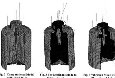
In computation, shell elements are used for the discretization of the main vessel and the support structure. The internal support structure is replaced by an thick plate of equivalent bending stiffness. 3D block elements are adopted for the rotating plug and the shielding components. Other internal equipments, such as pumps, IHX's and pipe lines, are all modeled as beams. The fluid is assumed to be viscoseless and incompressible and thus its influence to the structure results in an additional mass matrix. The computation model with FEM meshes is shown in Fig.2.
Modal analysis shows that the dominant vibration mode of the system is a beam-like shear deformation of the main vessel in combination with in-phase core motion, as shown in Fig. 3. The mode of the main vessel shear deformation with out-phase core motion has a much higher natural frequency than the dominant one, as shown in Fig. 4. Pumps, HIX's and pipe lines have even lower natural frequencies, as shown in Fig. 5. However they are contribute less to responses of the whole system under seismic excitation. Vibration frequencies for modes of importance to seismic response are listed in Table 1.
Table 1. Frequency for Modes of Importance to Seismic Excitation (Hz)
1 2 3 4 5 6 7
With Fluid 37.584 37.672 41.744 49.564 54.679 58.148 Without Fluid 40.067 40.206 41.750 49.806 55.761 58.268
Character Y in-phase X in-phase Torsional X Plug Y Plug Z
65.059 67.407 71.696 73.311 X out-phase Y out-phase
Concerning fluid-structure coupling effect, a detailed fluid-structure interaction analysis [8] shown that it may have a significant influence on circumferential vibration modes and may cause more than 40% decrease in modal frequencies. While for the dominant mode, modal frequency will only be slightly decreased and same to the other modes of importance to seismic excitation. It is also found that the additional fluid mass for the dominant mode is about 70% of the total coolant [8]. In this study, a factor of 0.7 is simply chosen in computing additional fluid mass for all modes concerned. This may cause certain inaccuracy, however, as mentioned before, the fluid-structure coupling has only a minor effect on modal frequencies, for which they are important to seismic response. The illustration might be that the major part of the fluid beneath the up-deck of the box-type internal support structure is enclosed in chambers. Its interaction with panels of the support structure will be transferred to the main vessel only through the supporting ring thus greatly reduced the coupling effect.
Dynamic response of the FBR vessel to seismic loads is calculated by using response spectrum analysis method. First 32 modes are adopted thought some of them may have a nearly zero participation factor. The input floor response spectrum is shown in Fig. 6 and the structural damping ration is taken to be 0.02. Response displacements and corresponding accelerations are given in Table 2. It is found that the maximum stress will be at the fixed end of the supporting skirt and be of the value of [~z[ = 27.014 MPa. It is compared well with that measured in the test, which is 30.0 MPa.
Table 2. Response Displacement and Acceleration Position CoreTop Core Bottom Pump Top IHX Top Plug Top Main Vessel Top
Strengthen Ring
Displacement (mm) 0.4615 0.3952 6.1041 3.9596
Acceleration (g) 2.4781 2.1469 8.6447 6.0002 7.1983 1.2968
0.8493 4.6723
0.3827 2.0426
SLOSHING ANALYSIS AND TRI-SINUSOIDAL WAVE RESPONSE
Main Vessel
Ring Region
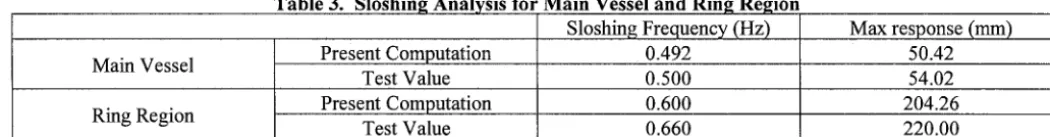
Table 3. Sloshing Analysis for Main Vessel and Ring Region Sloshing Frequency (Hz)
Present Computation 0.492
Test Value 0.500
Present Computation 0.600
Test Value 0.660
Max response (mm) 50.42 54.02 204.26 220.00
CONCLUSIONS
The computational model proposed is appropriate for the seismic analysis. Both numerical simulation and shaking table test confirms that the fluid-structure coupling has a relatively minor effect to vibration frequencies. Numerical study shows that localized vibration modes, particularly for pumps and IHX's may have vibration frequencies even lower than that of the main vessel. The sloshing frequency is calculated for fluid in the ring region with or without multi-immersed objects. Both the computed sloshing frequencies and response wave height to tri-sinusoidal wave excitation are confirmed in the test.
REFERENCES
1.
Fujita, K., Ito, T., Matsuo, T., Shimomura, T. and Morishita, M., Aseismic study on the reactor vessel of a fast breeder reactor, Nuclear Engineering and Design, Vol. 83, 1984, pp. 47-61.2. Ma, D. C., Chang, Y. W. and Seidensticker, R. W., An overview of seismic-induced hydrodynamic phenomena in LMR reactor tanks, Trans. Of the 1 l th International Conference on Structural Mechanics in Reactor Technology, Vol. E, pp.425-436, Tokyo, Japan, 1991.
3. Ma, D. C., Seismic analysis of a large LMFBR with fluid-structure interaction, Trans. Of the 8th International Conference on Structural Mechanics in Reactor Technology, Vol. E, pp. 309-314, Brussel, Belgium, 1985.
4. Sakurai, A. and Kurihara, C., Fluid-coupled vibration analysis of reduced models for pool type LMFBR, Trans. Of the 8th International Conference on Structural Mechanics in Reactor Technology, Vol. E, pp.333, Brussel, Belgium, 1985. 5. Fujita, K. Ito, T., Tashimo, M., Sakurai, A. and Kurihara, C., Study on the seismic response of reactor vessel of pool-type
LMFBR including fluid-structure interaction, Trans. Of the 9th International Conference on Structural Mechanics in Reactor Technology, Vol. E, pp.485-492, Lausanne, Switzerland, 1987.
6. Ma, D. C. and Gvildys, J., Seismic analysis of a 400-MW pool-type reactor, Trans. Of the 9th International Conference on Structural Mechanics in Reactor Technology, Vol. E, pp.493-498, Lausanne, Switzerland, 1987.
7. Wang, Y. and Gvildys, J., Response of a pool-type LMR to seismic load, Trans. Of the 10th International Conference on Structural Mechanics in Reactor Technology, Vol. E, pp. 109-114, Anaheim, USA, 1989.
8. Qian, J., Weng, Z. Y. and Lu, X. L., Seismic analysis of FBR main vessel with fluid-structure interaction, Nuclear Power Engineering (in Chinese), 1998, pp.240-245.
9. Weng, Z. Y., Qian, J., Xu, L. C. and Wu, J. C., Seismic response analysis for the main vessel of a pool-type fast breeder reactor, Proc. of the first International Conference on Structural Engineering, pp.527-534, Kunming, China, October 1999.
10. Weng, Z. Y., Qian, J. and Lu, L., Dynamic analysis of a scaled FBR test model, Proc. of International Conference on Advances in Structural Dynamics, Hong Kong, December 2000.
12-_
t1-__
I
I
; ~ , ~ ---2
~ - - - - _.~ , _ _ _ -
i I
~ . .
_i
I ---lO
1 ~ r o t a t i n g p l u g 2 ~ c o n e - t y p e t o p 3 ~ I H X
4 ~ m a i n v e s s e l
5 ~ s h i e l d i n g c o m p o n e n t s 6 ~ c o r e
7 ~ s t r e n g h t e n r i n g
8 ~ b o x - t y p e i n t e r n a l s u p p o r t s t r u c t u r e 9 ~ e n d - c l o s u r e
10 ~ s u p p o r t skirt 11 ~ p u m p
12 - - s u r f a c e o f s o d i u m c o o l a n t
Fig. 1 Layout of the Scaled L M F B R Test Model
Fig. 2 Computational Model with F E M Mesh
i /
i/
Fig. 3 The Dominant Mode to Seismic Load
,j
iFig. 5 Vibration Mode of
Pumps and IHX's
01
1
10
100
Fig.6 The input floor response spectrum
0.30 /
t main vessel
f - - - -ring region.
[ ,t ,
°15 t
f , ,
:
',
o,oo ~
- ~ " ' ~
2"-'~,
, ,
-0.15
T/To \
-0.30
0.0 0.8 1.6 2.4 3.2