Pandian Saraswathi Yadav Engineering College, Arasanoor, Sivagangai, Tamilnadu, India
Area and Delay Efficient Digital Comparator
Poomaran
1, Ramesh Kumar
2PG Scholar, NPR Engineering College, Dindigul, Tamil Nadu, India1
Assistant Professor, NPR Engineering College, Dindigul, Tamil Nadu, India2
ABSTRACT: Quantum-dot cellular automata (QCA) tend to be an attractive emerging technology suitable for the development of ultra-dense low-power high-performance digital circuits. Efficient solutions have recently been proposed for several arithmetic circuits,such as adders, multipliers, and comparators. This paper proposes a new design approach oriented to the implementation of binary comparators in QCA. The proposed work uses novel implementation strategies, methodologies and new formulations of basic logic equations to make the comparison function applied to comparator efficient. The new strategy has been exploited in the design of two different comparator architectures and for several operands word lengths.The comparators are proposed here exhibit significantly higher speed and reduced overall area. The existing and proposed comparators are synthesized using Xilinx and performance is evaluated in terms of number of gates and delay.
KEYWORDS: Binary comparators, majority gates, Quantum-dot cellular automata (QCA).
I. INTRODUCTION
Quantum-dot cellular automata (QCA) technology
provides a promising opportunity to overcome the approaching limits of conventional CMOS technology [1]–[6]. For this reason, in recent years the design of logic circuits based on QCA received a great deal of attention, and special efforts have been directed towards arithmetic circuits, such as adders [7]–[14],multipliers [15]–[21] and comparators [22]–[28].Even though comparators are key elements for a wide range of applications [29][30].QCA implementations existing in the literature are mainly provided for comparing two single bits. Only few examples of comparators able to process n-bit operands, with n > 2, are available [24][26][27].The comparator described in [22] simply computes the XNOR function to check whether two input bits a and b match each other.The structures proposed in [23]–[28] have higher computational capabilities, and circuits able to recognize all the three possible conditions in which a = b, a > b and a< b (full comparators) are described in [23][24]and [27]. The 1-bit implementation is proposed in [23] and then improved in [25], has been exploited in [27] to design a parallel n-bit full comparator. An example of serial structures is provided in [24], whereas the n-bit comparator described in [26] can recognize only the case in which, A and B being the n bit inputs, A≥ B.
With respect to other QCA designs, the latter exhibit reduced delays, area occupancy and number of used cells.
This paper focuses on the design of efficient parallel QCA based n-bit full comparators. The novel theorems were applied to achieve innovative QCA based structures of n-bit full comparators that were laid out and are synthesized using Xilinx Tool. The rest of the paper is organized as follows: a brief background of the QCA design approach and existing QCA implementations of binary comparators is given in Section II; the proposed comparator based on new theorems and corollaries are then enunciated and demonstrated in Section III; Simulation results and comparison of performance is done in Section IV; Finally, in Section V, conclusion ispresented.
II. BACKGROUND AND RELATED WORKS
tendto align their polarizations. However, QCA cells do not have intrinsic data flow directionality. Therefore, to achieve controllable data directions, the cells within a QCA design are partitioned into the so-called clock zones that are progressively associated with four clock signals, each phase shifted by 90º. This clock scheme, named the zone clocking scheme, makes the QCA designs intrinsically pipelined, since each clock zone behaves like a D-latch [20].QCA cells are used for both logic structures and interconnections that can exploit either the coplanar cross or the bridge technique [1][2][6][31][32]. The fundamental logic gates inherently available within the QCA technology are the inverter and the majority gate (MG). Given three inputs a, b and c, the MG performs the logic function reported in [1] provided that all input cells are associated with the same clock signal clkx (with x ranging from 0 to 3), whereas the remaining cells of the MG are associated with the clock signal clkx+1
M (a, b, c) = a • b + a • c + b • c (1)
There are several QCAdesigns of comparators in the literature [22]–[28]. A 1-bit binary comparator receives twobits a
andb as inputs and establishes whether they are equal, less than or greater than each other. These possible states are represented through three output signals, here named AeqB, AbigB,BbigA, that are asserted, respectively, when a = b,
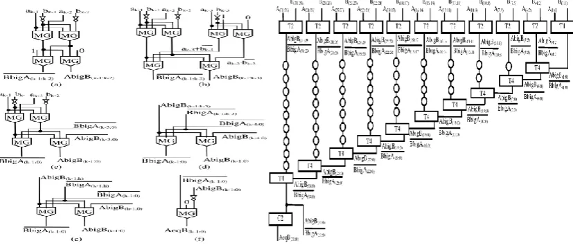
a>b, and a<b. Full comparators are those that can separately identify all the above cases, whereas non-full comparators recognize just one or two of them. As an example, the comparator designed in [22] and depicted in Fig. 1(a) can verify only whether a = b. Conversely,the circuits shown in Fig. 1(b) and (c), proposed in [23] and [24],are full comparators. The latter also exploits two 1-bit registers D to process n-bit operands serially from the least significant bit to the most significant one.With the main objective of reducing the number of wire crossings, which is still a big challenge of QCA designs [33]–[35] in [25] the universal logic gate (ULG) f(y1, y2, y3) =M(M(y1, y2 , 0),M(y1, y3 , 1),1)was proposed and then usedto implement the comparator illustrated in Fig. 1(d). It isworth noting that, two n-bit numbers A(n−1:0) =
an−1 . . . a0 and B(n−1:0) = bn−1 . . . b0can be processed by cascading n instances of the 1-bit comparator. Each
instance receives as inputs the ith bits aiand bi (with i = n − 1, . . . ,0) of the operands and the signals AbigB(i−1:0) and
BbigA(i−1:0) . The former is asserted when the subword A(i−1:0) = ai−1 . . . a0represents a binary number greater than
B(i−1:0) = bi−1 . . . b0 . In a similarway, BbigA(i−1:0) is set to 1 when A(i−1:0) < B(i−1:0). Theoutputs AbigB(i:0) and BbigA(i:0) directly feed the next stage.It can be seen that this circuit does not identify the case in which A = B, therefore it cannot be classified as a full-comparator.With the main objective of reducing the number of wirecrossings, which is still a big challenge of QCA designs[33]–[35], in [25] the universal logic gate (ULG) f(y1, y2, y3) = M(M(y1, y2 , 0),M(y1, y3 , 1), 1) was proposed and then used to implement the comparator illustrated in Fig. 1(d). It is worth noting that, two n-bit numbers A(n−1:0) = an−1 . . . a0 and B(n−1:0) = bn−1 . . . b0 can be processed by cascading n
instances of the 1-bit comparator. Each instance receives as inputs the ith bits aiand bi (with i = n − 1,0) of the operands and the signals AbigB(i−1:0) and BbigA(i−1:0) . The former is asserted when the subwordA(i−1:0) = ai−1 . . . a0 represents a binary number greater than B(i−1:0) = bi−1 . . . b0. .In a similarway, BbigA(i−1:0) is set to 1 when
A(i−1:0) < B(i−1:0). The outputs AbigB(i:0) and BbigA(i:0) directly feed the next stage. It can be seen that this circuit does not identify the case in which A = B, therefore it cannot be classified as a full-comparator.
The design described in [26] exploits a tree-based (TB) architecture and exhibits a delay that in theory logarithmically increases with n. The 2-bit version of such designed comparatoris illustrated in Fig. 1(e).
Also the full comparator proposed in [27] exploits a TB architecture to achieve high speed. As shown in Fig. 1(f), where 4-bit operands are assumed, one instance of the 1-bit comparator presented in [23] is used for each bit position. The intermediate results obtained in this way are then further processed through a proper number of cascaded 2-input OR and AND gates implemented by means of MGs having one input permanently set to 1 and 0, respectively.
Pandian Saraswathi Yadav Engineering College, Arasanoor, Sivagangai, Tamilnadu, India
Fig. 1. QCA-based comparators presented in: (a) [22]; (b) [23]; (c) [24];(d) [25]; (e) [26]; (f) [27].
III.THEOREMS AND COROLLORIESOF n-BIT FULL COMPARATORS
In this section, four original theorems and two corollaries are enunciated that can significantly increase the speed performances of QCA-based designs of full comparators and can significantly reduce the number of used MGs and inverters with respect to existing comparators, thus reducing also the number of used cells and the overall active area.
The novel formulations can be exploited in the design of n-bit full comparators splitting the operands A(n−1:0) =
an−1 . . . a0 and B(n−1:0) = bn−1 . . . b0 into a proper number of 2-bit and 3-bit subwords that can be compared applying Theorems 1 and 2. The intermediate results obtained in this way can be then further processed by applying Theorems 3 and 4 together with Corollaries 1 and 2.
Theorem 1:
If A(k−1:k−2) = ak−1ak−2 and B(k−1:k−2) = bk−1bk−2 ,with k = 2, 4, . . ., n – 2, n, are two 2-bit subwords of the
n-bit numbers A(n−1:0) and B(n−1:0) , respectively, then AbigB(k−1:k−2) as defined in (2) is equal to 1 if and only if
Theorem 2:
If A(k−1:k−3) =ak−1ak−2ak−3 and B(k−1:k−3) =bk−1bk−2bk−3 , with k = 3, 6, . . . , n − 3, n, are 3-bit subwords of the n-bit numbers A(n−1:0) and B(n−1:0), respectively, then AbigB(k−1:k−3) as defined in (4) is equal to 1 if and only if A(k−1:k−3) > B(k−1:k−3) ; BbigA(k−1:k−3) as given in (5) is equal to 0 if and only if A(k−1:k−3) < B(k−1:k−3).
Theorem 3:
Given two n-bit numbers A(n−1:0) and B(n−1:0) ,(6) gives AbigB(n−1:0) = 1 if and only if A(n−1:0) > B(n−1:0) , whereas (7) gives BbigA(n−1:0) = 0 if and only if A(n−1:0) <B(n−1:0).
Theorem 4:
If A(n−1:0) and B(n−1:0) are two n-bit numbers,thenAbigB(n−1:n−3) and BbigA(n−1:n−3) being computed by (4) and(5), respectively, then AbigB(n−1:0) as defined in (8) is equal to 1 if and only if A(n−1:0) > B(n−1:0), whereas BbigA(n−1:0) asdefined in (9) is equal to 0 if and only if A(n−1:0) <B(n−1:0).
Corollary 1:
Let’s consider two n-bit numbers A(n−1:0) and B(n−1:0), and let’s suppose that they are split into the
subwordsA(n−1:h),A(h−1:0),B(n−1:h) and B(h−1:0).If AbigB(n−1:h), AbigB(h−1:0), BbigA(n−1:h) and BbigA(h−1:0) are computed by applying Theorems 3 and 4, then AbigB(n−1:0) as defined in (10) is equal to 1 if and only if A(n−1:0)
> B(n−1:0), whereas BbigA(n−1:0) as defined in (11) is equal to 0 if and only if A(n−1:0) < B(n−1:0).
Corollary 2:
Given two n-bit numbers A(n−1:0) and B(n−1:0), if AbigB(n−1:0) and BbigA(n−1:0) are computed by applyingTheorems 1, 2, 3, and 4 and/or Corollary 1, then AeqB(n−1:0)defined in (12) is equal to 1 if and only if
Pandian Saraswathi Yadav Engineering College, Arasanoor, Sivagangai, Tamilnadu, India
In order to exploit the novel approach, the operandsA(n−1:0) and B(n−1:0) are split into a proper number of 2- and3-bit subwords that are compared applying Theorems 1 and 2.The results obtained comparing 2- and 3-bit subwords are then combined by applying Theorems 3 and 4 together with Corollaries 1 and 2.
IV. PROPOSED BINARY COMPARATOR
The circuits illustrated in Fig. 2 were designed to implement in QCA the novel equations demonstrated in the previous Section. The generic module Ti, with i ranging between 1 and 4, implements the equations enunciated in the
iththeorem,whereas C1 and C2 compute the signals AbigB(k−1:0),BbigA(k−1:0), and AeqB(k−1:0) as shown above in Corollaries 1 and 2, respectively. As examples of application, the above QCA modules have been used to design two different structures of full comparators named cascade-based and TB architectures. However, many other structures can be designed by combining the basic modules in different manners.
A) Novel QCA Comparators
The first proposed comparator exploits a cascade-based (CB) architecture. To explain better how the overall computation is performed, the schematic diagram illustrated in Fig. 3 is provided. It shows a possible implementation of a 32-bit comparator based on the proposed theory.
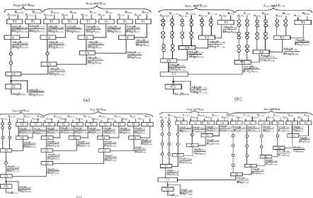
Fig. 2. QCA modules: (a) T1; (b) T2; (c) T3; (d) T4; (e) C1; and (f) C2.Fig. 3.Novel 32-bit CB full comparator.
Circles visible in Fig. 3 indicate the additional clock phases that have to be inserted on wires to guarantee the correct synchronization of the overall design. The CB full comparator was designed for operands wordlengths ranging from 2 to 32 and using, for n >2, the split criterion summarized in Table I. Obviously, alternative splits could be used.
TABLE ISPLITTING CRITERION ADOPTED IN THE CB COMPARATORS
that the modules T1 and T2 contribute to the computational path with one inverter and two MGs. Each instance of T4 introduces one more MG,whereas C2 is responsible for one MG and one inverter. As a consequence, the critical computational path of the novel n-bit CB full comparator consists of n/3+ 3 MGs and 2 inverters. As an example, the 32-bit implementation depicted in Fig. 3 has the worst-case path made up of 13 MGs and 2 inverters.The number of MGs within the computational path of the above described comparator linearly increases with n. An alternative solution presented here adopts a TB architecture to achieve shorter computational paths. When this approach is exploited, several implementations of an n-bit full comparator can be designed differently combining the novel theorems and corollaries, as well as their QCA implementations depicted in Fig. 2.
The TB comparators implement the comparison function recursively. The operands A and B are preliminarily partitioned as A = AMSBALSB and B = BMSBBLSB. The portions AMSB andBMSB are compared independently of the portions ALSB andBLSB. The depth of the recursion directly impacts the whole architecture. Examples of TB structures designed for 16- and 32-bit comparators are illustrated in Fig. 4. In Fig. 4(b) and (d), the recursion with its minimum depth is adopted. The portions AMSB and BMSB, as well as the portions ALSB and BLSB, areseparately compared trough two independent CB architectures. The overall result is finally built with the modules C1 and C2. Fig. 4(a) and (c) shows comparators designed adopting deeper recursions. In the following of the paper, the 16- and 32-bit TB implementations illustrated in Fig. 4(b) and (d) are deeply analyzed. Referring to the QCA modules depicted in Fig. 2, it can be easily verified that the former uses 35 MGs and 17 inverters and its critical computational path consists of 7 MGs and 2 inverters, whereas the latter utilizes 83 MGs and 33 inverters and it has a worst-case path composed by 9 MGs and 2 inverters.
Pandian Saraswathi Yadav Engineering College, Arasanoor, Sivagangai, Tamilnadu, India
V.RESULTS AND DISCUSSION
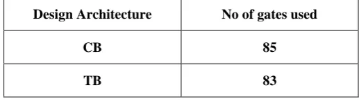
The performance of the tree based and cascade based architectures are compared in terms of number of gates.The cascade based approach uses large number of MGs compared to Tree based approach.
Fig. 5.Equivalent Cascade based comparator RTL diagramFig. 6. Equivalent Tree based comparator RTL diagram
Fig. 7.Synthesis result for Cascade based comparatorFig. 8. Synthesis result for Tree based comparator
TABLE II RESULTS
Design Architecture No of gates used
CB 85
TB 83
IV.CONCLUSION
REFERENCES
[1] C. S. Lent, P. D. Tougaw, W. Porod, and G. H. Bernestein, “Quantumcellular automata,” Nanotechnology, vol. 4, no. 1, pp. 49–57, 1993. [2] M. T. Niemer and P. M. Kogge, “Problems in designing with QCAs: Layout= timing,” Int. J. Circuit Theory Appl., vol. 29, pp. 49–62, 2001. [3] G. H. Bernstein,A. Imre,V.Metlushko,A.Orlov, L. Zhou, L. Ji,G. Csaba,and W. Porod, “Magnetic QCA systems,” Microelectron. J., vol. 36, pp. 619–624, 2005.
[4] J.Huang and F. Lombardi, Design and Test of DigitalCircuits by Quantum-Dot Cellular Automata. Norwood, MA, USA: Artech House, 2007. [5] W. Liu, L. Lu, M. O’Neill, and E. E. Swartzlander Jr., “Design rules forquantum-dot cellular automata,” in Proc. IEEE Int. Symp. Circuits Syst. (ISCAS), Rio De Janeiro, Brazil, May 2011, pp. 2361–2364.
[6] K. Kim, K. Wu, and R. Karri, “Towards designing robust QCA architectures in the presence of sneak noise paths,” in Proc. IEEE Design, Automation Test Eur. Conf. Exhib. (DATE),Munich, Germany,Mar. 2005,pp. 1214–1219.
[7] K. Navi, M. H. Moaiyeri, R. F. Mirzaee, O. Hashemipour, andB. M. Nezhad, “Two new low-power full adders based on majority-not gates,” Microelectron. J., vol. 40, pp. 126–130, 2009.
[8] H. Cho and E. E. Swartzlander Jr., “Adder design and analyses forquantum-dot cellular automata,” IEEE Trans. Nanotechnol., vol. 6, no. 3, pp. 374–383, May 2007.
[9] H. Cho and E. E. Swartzlander Jr., “Adder and multiplier design inquantum-dot cellular automata,” IEEE Trans. Comput., vol. 58, no. 6, pp. 721–727, Apr. 2009.
[10] V. Pudi and K. Sridharan, “Efficient design of a hybrid adder in quantumdot cellular automata,” IEEE Trans. VLSI Syst., vol. 19, no. 9, pp. 1535– 1548, Jul. 2011.
[11] M. Gladshtein, “Quantum-dot cellular automata serial decimal adder,”IEEE Trans. Nanotechnol., vol. 10, no. 6, pp. 1377–1382, Nov. 2011. [12] V. Pudi and K. Sridharan, “Low complexity design of ripple carry andBrent-Kung adders in QCA,” IEEE Trans. Nanotechnol., vol. 11, no. 1, pp. 105–119, Jan. 2012.
[13] S. Perri and P. Corsonello, “New methodology for the design of efficientbinary circuits addition inQCA,” IEEE Trans.Nanotechnol., vol. 11, no. 6,pp. 1192–1200, Nov. 2012.
[14] V. Pudi and K. Sridharan, “New decomposition theorems on majoritylogic for low-delay adder designs in quantum dot cellular automata,”
IEEE Trans. Circuits Syst. II: Exp. Brief, vol. 59, no. 10, pp. 678–682,Oct. 2012.
[15] H. Cho and E. E. Swartzlander Jr., “Serial parallel multiplier design inquantum-dot cellular automata,” in Proc. IEEE Symp.Comput. Arithmetic,2007, pp. 7–15.
[16] S. W. Kim and E. E. Swartzlander Jr., “Parallel multipliers for quantumdot cellular automata,” in Proc. IEEE Nanotechnol. Mater. Devices Conf., 2009, pp. 68–72.
[17] S. W. Kim and E. E. Swartzlander Jr., “Multiplierswith coplanar crossings for quantum-dot cellular automata,” in Proc. IEEE Int. Conf. Nanotechnol., 2010, pp. 953–957.
[18] W. Liu, L. Lu, M. O’Neill, and E. E. Swartzlander Jr., “Montgomerymodular multiplier design in quantum-dot cellular automata using cut-set retiming,” in Proc. IEEE Int. Conf. Nanotechnol., 2010, pp. 205–210.
[19] L. Lu, W. Liu, M. O’Neill, and E. E. Swartzlander Jr., “QCA systolicmatrix multiplier,” in Proc. IEEE Annu. Symp. VLSI, 2010, pp. 149–154. [20] J. D.WoodandD.Tougaw, “Matrix multiplication using quantum-dot cellular automata to implement conventional microelectronics,” IEEE Trans.Nanotechnol., vol. 10, no. 5, pp. 1036–1042, Sep. 2011.
[21] L. Lu, W. Liu, M. O’Neill, and E. E. Swartzlander Jr., “QCA systolicarray design,” IEEE Trans. Comput., vol. 62, no. 3, pp. 548–560, Mar. 2013.
[22] J. R. Janulis, P. D. Tougaw, S. C. Henderson, and E. W. Johnson, “Serialbit-stream analysis using quantum-dot cellular automata,” IEEE Trans. Nanotechnol., vol. 3, no. 1, pp. 158–164, Mar. 2004.
[23] K. QiuandY. Xia, “Quantum-dots cellular automata comparator,” in Proc. Int. Conf. ASIC, 2007, pp. 1297–1300.
[24] B. Lampreht, L. Stepancic, I. Vizec, and B. Zankar, “Quantum-dot cellular automata serial comparator,” in Proc. EUROMICRO Conf. Digital Syst.Design Architectures, Methods Tools, 2008, pp. 447–452.
[25] Y. Xia and K. Qiu, “Design and application of universal logic gate basedon quantum-dot cellular automata,” in Proc. IEEE Int. Conf. Commun. Technol., 2008, pp. 335–338.
[26] M. D.Wagh, Y. Sun, and V. Annampedu, “Implementation of comparison function using quantum-dot cellular automata,” in Proc. Nanotechnol.Conf. Trade Show, 2008, pp. 76–79.
[27] Y. Xia and K. Qiu, “Comparator design based on quantum-dot cellularautomata,” J. Electron. Inf. Technol., vol. 31, no. 6, pp. 1517–1520, 2009.
[28] S. Ying, T. Pei, and L. Xiao, “Efficient design of QCA optimal universallogic gate ULG.2 and its application,” in Proc. Int. Conf. Comput. Appl.Syst. Modeling (ICCASM), 2010, pp. 392–396.
[29] S. Perri and P. Corsonello, “Fast low-cost implementation of single-clockcycle binary comparator,” IEEE Trans. Circuits Syst. II: Exp. Briefs, vol. 55, no. 12, pp. 1239–1243, Dec. 2008.