U-Slot Microstrip Patch Antenna for Wireless
Application
J.Venkatachalapathi 1, M.Kaanchana2, T.Adhilakshmi3, B.Vaishnavi4, D.Sriganesh5
Assistant Professor, Department of Electronic and Communication Engineering, Dr. S.J.S Paul Memorial College of Engineering and Technology, Pondicherry, India1
B.Tech, Department of Electronic and Communication Engineering, Dr. S.J.S Paul Memorial College of Engineering and Technology, Pondicherry, India2, 3, 4, 5
ABSTRACT: The main objective of this paper is to simulate and design a single u-shaped microstrip patch antenna with operating frequency of 5.5GHz. This type of antenna has to be designed using a substrate having a low dielectric constant in order to achieve low return loss. The microstrip antenna consists of the rectangular patch on the top of the dielectric substrate and over which a u-shaped slot has been made to reduce the size of the antenna. The reduction in the size of the antenna results in improved gain and the return loss of the antenna. Therefore, the single u-shaped microstrip patch antenna has a broad bandwidth and can be used for wireless applications. The antenna has been simulated using HFSS (High frequency synthetic simulator) software, a 3D simulator which shows the accurate simulated result compared with other simulation software.
KEYWORDS :single U slot antenna, RT duroid 5880 substrate, HFSS software, 3D simulator, gain, return loss.
I.INTRODUCTION
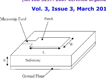
FIG 1 – MICROSTRIP PATCH ANTENNA
In order to achieve effective radiation of antenna, the designed antenna must have a substrate of low dielectric constant therefore RT duroid is chosen and which results in the better performance of antenna and provides better efficiency, larger bandwidth and better radiation with reduced number of side lobes.The dielectric constant for the RT duroid 5880 is 2.2, which is comparatively smaller than the other substrates.The input is given using different feed techniques and different feeding methods are available to feed microstrip patch antenna. The radio frequency power is fed directly to the radiating patch using microstrip line feed method. There are many feeding techniques, which includes microstrip line feed, coaxial line feed, aperture coupling and proximity coupling method. In the microstrip line feed, a conducting strip is connected directly to the center of the patch by etching the substrate and the conducting strip should be smaller in width when compared with the width of the microstrip patch. The inset cut is made in the patch to increase the radiation of the antenna.
In the coaxial line feed technique, the inner conductor of the coaxial strip extends throughout the dielectric and is soldered to the radiating patch, while the outer conductor is coupled to the ground plane. Eventhough the feeding can be given at any desired location inside the patch, the modeling will be difficult using this technique.In the aperture coupled feed, the radiating patch and the microstrip feed line are separated by the ground plane. In this technique, the patch and the feed line is coupled with the ground plane through the slot. The slot should be placed at the centre in order to have low cross polarization but due to multiple layers and the increased thickness, the antenna fabrication is difficult.In the proximity coupled feed, which is otherwise called as the electromagnetic coupling, two dielectric substrates are used and the feed line is between the two substrates among which the radiating patch is on the top of the upper substrate and the ground plane is on the lower substrate. Using this technique, the unwanted radiations can be eliminated but the antenna fabrication is difficult because of the two dielectric substrates. Therefore, the microstrip line feed has been chosen for the rectangular microstrip antenna for better radiation and it is designed using the operating frequency of 5.5GHz and has been simulated using HFSS software.
II. RELATED WORK
L.Economou et al. presents microstrip patch antennas on glass for vehicle applications. Circular patches printed on RT Duroid were used, with glass laminated superstrates which excited surface waves of between 10% and 20% of the input power. Patches and microwave circuits within the glass laminate will introduce even more uncertainty into the resonant frequency and bandwidth. Overall, this could be a significant problem for microstrip antennas on automotive glass where communication bands demand bandwidths of 5% and above. Dual-frequency planar antenna for handsets is presented by Chiba et al.
three-these antennas are presented and performance trends are established. From three-these trends, valuable insight to the optimum design, namely broad bandwidth, small size, and ease of manufacturing, is given.
R.Leclaratne et al. presents a novel microstrip patch antenna suitable for satellite communications [4]. It is designed by using two semi-discs with single feeding. The antenna is circularly polarized and suitable for mobile satellite communications and if fed as individual semi-rings as a dual band orthogonally polarized antenna.
Lafond et al. presents aperture coupled microstrip patch antenna with thick ground plane.The thickness has a strong effect on impedance matching at high frequencies owing to the ratio between the thickness and the wavelength, which increases with frequency.
III.SCOPE OF RESEARCH
The aim of the project is to design u-slot rectangular microstrip Patch antenna and to study their radiation pattern, return loss, VSWR, gain and directivity. Length and Width of the antenna can be predicted using the design equation. Microstrip antenna is simulated by Ansoft HFSS software which has its operating frequency range (5.18-5.8)GHz. As in modern communication is concerned in size reduction and portability, miniaturization and good cost to quality ratio are the main things in our project.
IV. PROPOSED METHODOLOGY AND DISCUSSION
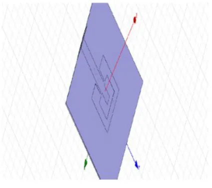
Here the existing system design parameter has been calculated and the designed frequency of 5.5 GHz was simulated using HFSS software. The dielectric material selected for this design is RT duroid 5880. The design specifications for patch are below:
Dielectric constant-2.2
Height of the substate-1.2mm
And the feed line is realized on the same substrate layer.
FIG 2- DESIGN OF U-SHAPE MICROSTRIP ANTENNA PATCH
The properties of substrates are:
DESIGN PARAMETERS:
The various design parameters are calculated as follows: 1. Width (W)
2. Effective permittivity (εreff )
3. Effective length (Leff) 4. Delta length (ΔL) 5. Actual length (L)
6. Width of the ground (Wg)
7. Length of the ground (Lg)
These parameters are calculated for operating frequency of 5.5GHz has the length of 26.75mm and the delta length of 0.2367. It has RT duroid 4880 as the dielectric substrate which has the relative permittivity which is equal to 2.2.
FORMULA USED:
WIDTH:
DIELECTRIC CONSTANT:
EFFECTIVE LENGTH:
PARAMETER RT DUROID 5880
Dielectric constant 2.2 Loss tangent 0.0004 Water absorption 0.2%
Tensile strength 450MP Volume resistivity 2x10^7 mho(cm) Surface resistivity 3x10^7mho(cm) Breakdown voltage >60 kV
ACTUAL LENGTH:
WIDTH OF GROUND:
LENGTH OF GROUND:
VI. EXPERIMENTAL RESULTS
There are some parameters that affect the antenna performance in which two of them have a very noticeable effect in determining the performance of the antenna. The return loss has become efficient according to the parameter changes and these parameter effects will be explained and summarized in this section.
RETURN LOSS:
The return loss for the proposed system is shown
.
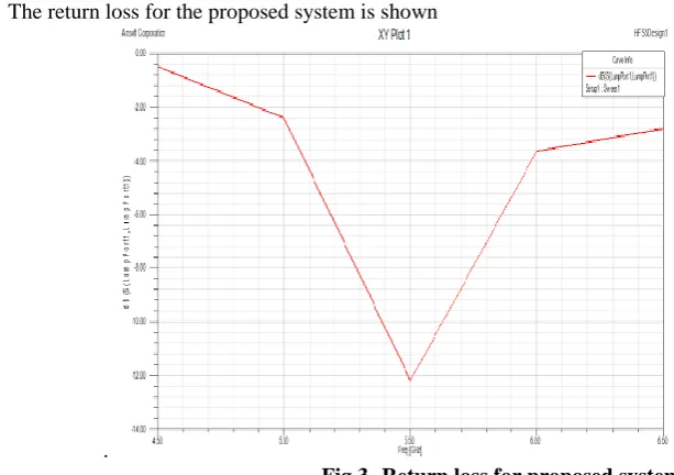
Fig 3- Return loss for proposed system
Fig 3 shows the return loss for the single u-slot antenna which is the simulated result. From the Fig 3, it can be shown that the U-slot microstrip patch antenna at 5.5GHz results in the broadening the bandwidth of the antenna. The graph is plotted for frequency in GHz versus return loss in dB. The graph is plotted for the frequency ranges from 4.50GHz to 6.50GHz and the return loss is shown from 0dB to -14dB.
Since the antenna has been designed for 5.5GHz and XYplot shows the return loss of -12.8dB at the operating frequency where there is more impedance matching and low return loss in order to achieve effective radiation pattern. The impedance mismatch occurs from 4.50GHz frequency to -5.23GHz and it results in somewhat low return loss and the frequency from 5.8GHz to 6.5GHz frequency, again due to impedance mismatch, the return loss increases and results in higher return loss which results in distortion and affects the effective radiation of the antenna.
RADIATION PATTERN
Fig 4- Radiation pattern for proposed system
The designed antenna is radiating all its power in one direction and therefore the optimized antenna has result with the effective radiation pattern and therefore the side lobes or nulls in the pattern has been minimized and the better directivity is achieved. The radiation pattern for the proposed system antenna has angles in phi and theta. In the figure, phi is represented in red colour and theta is represented in purple colour. The antenna is radiated from the angle of 45 degrees and has the magnitude of 7.108dB.
VII.CONCLUSION
The proposed antenna explains and illustrates the simulation of the microstrip antenna with single u-shaped slot on the patch. This antenna is compact, have a flexible structure and easy to use compared with other antennas. Thus, the very low return loss of less than -12dB is achieved which is suitable for the wireless applications and in the c-band of satellite communication systems. This antenna has been simulated for the frequency of 5.5GHz and is well known for its wideband characteristics.
VIII. ACKNOWLEDGMENTS
We thank our HOD Dr.T.Thirumurugan, Ph.D. (Department of Electronics and Communication Engineering) to help us for creating this paper with his sincere guidance and Technical Expertise in the field of communication. The help of our guide Mr. J.Venkatachalapathi, M.Tech, Department of ECE, Dr, SJS Paul College of Engineering and Technology is really immense and once again I thank her for her great motivation. I thank Dr. SJS Paul College of Engineering and Technology to provide me such a standard educational environment so that I am able to understand the minute concepts in the field of Engineering and Technology.
REFERENCES
[1] Ahmed khidre, Kai-Fong lee, Alef Z. Elsher beni, and Fan yang” Wide band dual beam U-slot Microstrip antenna”. IEEE transaction on antenna and propogation, Vol 61, No: 3, match 2013.
[7] David M. Pozar. Considerations for millimeter wave printed antennas. IEEETransactions on Antennas and Propagation, 31(5):740{747, 1983. [8] “ Design of linear ly polar ized r ectangular maicrostrip patch antenna using IE3D/PSO”C. VISHNU VARDHANA REDDY and RAHUL RANA 2009
BIOGRAPHY
Mr. J.Venkatachalapathi is working as a Assistant Professor (Department of ECE) in Dr. S.J.S PAUL MEMORIAL COLLEGE OF ENGINEERING AND TECHNOLOGY.He is interested in Electro Magnetic wave theory, wave guides and antennas, Digital signal processing, signals and system.
Ms. M.Kaanchana is a student who is pursuing B.Tech (Electronics and Communication Engineering) in Dr. S.J.S PAUL MEMORIAL COLLEGE OF ENGINEERING AND TECHNOLOGY. He is interested in Electro Magnetic wave theory, wave guides and antennas, Digital signal processing, signals and system
Ms. T.Adhilakshmi is a student who is pursuing B.Tech (Electronics and Communication Engineering) in Dr. S.J.S PAUL MEMORIAL COLLEGE OF ENGINEERING AND TECHNOLOGY. He is interested in Digital circuits, Digital signal processing, and Electronic circuits.
Ms. B.Vaishnavi is a student who is pursuing B.Tech (Electronics and Communication Engineering) in Dr. S.J.S PAUL MEMORIAL COLLEGE OF ENGINEERING AND TECHNOLOGY. He is interested in VLSI design, Digital signal processing, and digital electronics.