Low Complexity Cordic Architecture for
MIMO Decoder
Rameesa Bava, Simy M Baby
M.Tech Student,
Dept. of ECE
, Ilahia College of Engineering and Technology, Muvattupuzha, Ernakulam, Kerala,India
Asst. Professor,
Dept. of ECE
, Ilahia College of Engineering and Technology, Muvattupuzha, Ernakulam, Kerala,India
ABSTRACT: In this, I present a MIMO decoding accelerator chip with a low complexity rotation unit. A low complexity CORDIC architecture is used for rotation unit. This accelerator targets multiple-input-multiple-output (MIMO) decoding tasks of orthogonal frequency-division multiplexing (OFDM) systems. The work is motivated by the adoption of MIMO and OFDM by almost all existing and emerging high-speed wireless data communication systems. It delivers full programmability across different MIMO decoding algorithms and this low complexity CORDIC increases the speed of accelerator chip. Given its programmability, the accelerator is an ideal solution for today’s smart phones that implement multiple MIMO-OFDM waveforms on the same platform.
KEYWORDS: CORDIC, Multiple-input-multiple-output (MIMO) decoder, MIMO accelerator, orthogonal frequency-division multiplexing (OFDM).
I. INTRODUCTION
Most high-speed wireless communication standards adopt both multiple-input-multiple-output and orthogonal frequency division multiplexing operation. MIMO-OFDM is the dominant air interface for 4G and 5G broadband wireless communication. It combines the MIMO technology which multiplies the capacity by transmitting different signals over multiple antennas and the OFDM technology which divides the radio channel into large number of closely spaced subchannels to provide more reliable communication even at high speed.
ISSN(Online): 2320-9801
ISSN (Print): 2320-9798
I
nternational
J
ournal of
I
nnovative
R
esearch in
C
omputer
and
C
ommunication
E
ngineering
(An ISO 3297: 2007 Certified Organization)
Vol. 3, Issue 10, October 2015
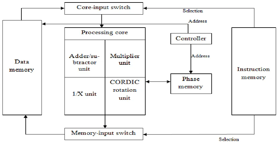
Figure 1. MIMO accelerator block diagram.
With new wireless communication standards and new MIMO decoding algorithms emerging every few years, existing systems need to be redesigned and upgraded not only to meet the newly defined standards, but also to allow integration of multiple standards onto the same platform and improve performance via more advanced decoding algorithms. This fact serves as the main motivation for this solution. A programmable hardware solution focused on the unique MIMO decoding operations of a MIMO system can help drive down nonrecurring engineering costs, can facilitate system upgrades to take advantage of emerging algorithms and can help minimize hardware duplications in system-on-a-chips that support multiple standards.
With new wireless communication standards and new MIMO decoding algorithms emerging every few years, existing systems need to be redesigned and upgraded not only to meet the newly defined standards, but also to allow integration of multiple standards onto the same platform and improve performance via more advanced decoding algorithms. This fact serves as the main motivation for this solution. A programmable hardware solution focused on the unique MIMO decoding operations of a MIMO system can help drive down nonrecurring engineering costs, can facilitate system upgrades to take advantage of emerging algorithms and can help minimize hardware duplications in system-on-a-chips that support multiple standards.
Several reconfigurable MIMO decoders have been reported in various publications. Each one of these reconfigurable decoders applies a fixed algorithm and provides enough hardware for the most complex configuration that it is capable of performing. These designs are neither flexible enough to be tailored to a new standard, nor can they implement diversely different algorithms. This paper presents an IC implementation for a MIMO decoder accelerator with a high speed rotation unit.
The MIMO accelerator is a software-programmable device that specializes in MIMO decoding, and MIMO signal processing for OFDM systems.
II. RELATED WORK
Several publications report on various designs and implementations for MIMO decoders. A system designer chooses a single MIMO decoding algorithm to be used by the system subject to the need to satisfy the specifications of the standard at hand. A hardware engineer then implements the chosen algorithm with constraints on complexity, performance, and power consumption-considering the parallel processing requirements for OFDM operation. This design cycle is typically repeated for every new communication standard.
One of such publication is a practical hardware friendly MMSE detector for MIMO-OFDM-based systems[1] .In this work, a highly optimized MMSE (minimum mean square error) MIMO detector was implemented. The work has resulted in a real-time field-programmable gate array-based implementation (FPGA). Another publication is VLSI implementation of MIMO detection using the sphere decoding algorithm[2]. Two ASIC implementations of MIMO sphere decoders is implemented in this paper. The first ASIC attains maximum-likelihood performance with an average throughput of 73 Mb/s at a signal-to-noise ratio (SNR) of 20 dB; the second ASIC shows only a negligible bit-error-rate degradation and achieves a throughput of 170 Mb/s at the same SNR. Another publication for decoding accelerator is energy efficient programmable MIMO decoder accelerator chip in 65-nm CMOS[6]. A programmable accelerator that delivers full programmability across different decoding algorithms is presented in this paper.
III. MIMO ACCELERATOR ARCHITECTURE
ISSN(Online): 2320-9801
ISSN (Print): 2320-9798
I
nternational
J
ournal of
I
nnovative
R
esearch in
C
omputer
and
C
ommunication
E
ngineering
(An ISO 3297: 2007 Certified Organization)
Vol. 3, Issue 10, October 2015
vectors (figure 2(b)). This multiplication unit is necessary for many MIMO decoding algorithms. Third is a reciprocal unit that computes a reciprocal of real numbers (figure 2(c)). It is mainly used for scaling the signal power. The fourth processing unit is the rotation unit. It consists of coordinate rotation (CORDIC) block. It uses rotation transform to calculate trigonometric and hyperbolic functions.
The data memory is the source for all operands as well as the target for the processing core results. Each memory location contains the data for a single OFDM subchannel. When an instruction is executed for a subchannel, the chunk of data associated with the subchannel is retrieved and then delivered to the core-input switch.
The core-input switch is a multiplexing circuit that selects and properly arranges the complex vectors needed by the processing core. The memory-input switch performs the same task, but in the reverse direction. It takes the outputs of the processing units and properly store in data memory locations. The instruction memory provides the programmer with complete control of the two switching circuits, thus delivering a significant amount of flexibility.
The phase memory is dedicated to the storage of the outputs of the rotation unit. The instruction memory activates the enable signals for other blocks depending upon the read and write instructions. Controller generates address for data memory to access the operands.
The fourth processing unit is the rotation unit. It consists of CORDIC block.
CORDIC (for COordinate Rotation DIgital Computer),also known as the digit-by-digit method and Volder's algorithm, is a simple and efficient algorithm tocalculate hyperbolic and trigonometric functions. It is commonly used when no hardware multiplier is available as the only operations it requires are addition, subtraction, bitshift and tablelookup.
IV. ROTATION UNIT
CORDIC uses simple shift-add operations for several computing tasks such as the calculation of trigonometric, hyperbolic and logarithmic functions, real and complex multiplications, division, square-root calculation and many others. CORDIC uses rotation transform to calculate trigonometric functions.
Consider rotation of a vector (x,y) by angle Ф as shown in figure 3(a). Then the values of x1 and y1 are:
x1 = x cos (Ф) − y sin (Ф)
y1 = x sin (Ф) + y cos (Ф)
Choose a unit vector (1,0) as staring vector (figure 3(b)), then
x1 = cos (Ф)
y1 = sin (Ф)
Thus we can calculate the trigonometric functions sin, cos by rotating a unit vector (1,0). In computer
arithmetic, we can rotate a unit vector using series of rotation with tabled values. The procedure is that iteratively rotate
(a) (b) (c) Figure 3. (a) Rotation of a vector (x,y). (b) Rotation of a unit vector (1,0). (c) Series of iterations.
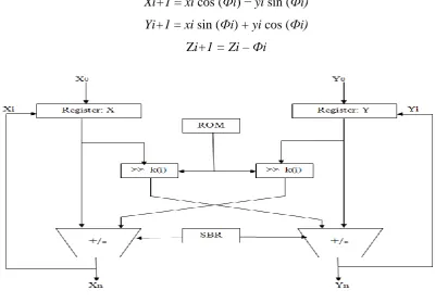
Xi+1 = xi cos (Фi) − yi sin (Фi)
Yi+1 = xi sin (Фi) + yi cos (Фi)
Zi+1 = Zi – Фi
Figure 4. CORDIC architecture.
To simplify, pick Ф(i) such that
tan (Фi) = di 2ˉ ͥ
ISSN(Online): 2320-9801
ISSN (Print): 2320-9798
I
nternational
J
ournal of
I
nnovative
R
esearch in
C
omputer
and
C
ommunication
E
ngineering
(An ISO 3297: 2007 Certified Organization)
Vol. 3, Issue 10, October 2015
Yi+1 = yi + di xi 2ˉ ͥ
Zi+1 = Zi – di tanˉ¹ 2ˉ ͥ
The scale factor of the CORDIC algorithm is given by
K= cos Ф = 1/(1+tan² Ф)¹/²
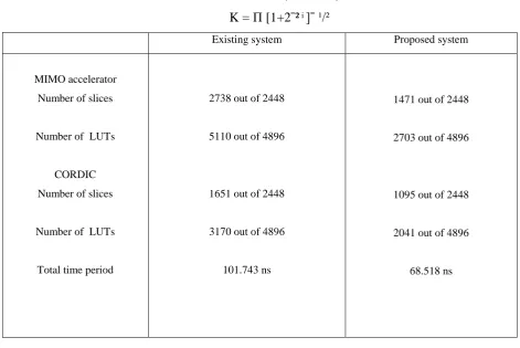
K = Π [1+2ˉ² ͥ ]ˉ ¹/²
Existing system Proposed system
MIMO accelerator
Number of slices
Number of LUTs
CORDIC
Number of slices
Number of LUTs
Total time period
2738 out of 2448
5110 out of 4896
1651 out of 2448
3170 out of 4896
101.743 ns
1471 out of 2448
2703 out of 4896
1095 out of 2448
2041 out of 4896
68.518 ns
Table 1. Comparison table.
By using CORDIC, computation of x(i+1) and y(i+1) requires only i-bit right shift and add/subtract operations.
If we reduce the number of iterations, then the number of shifts in the rotation unit is increased.
Xi+1 = xi − di yi 2^(ˉk(i))
Yi+1 = yi + di xi 2^(ˉk(i))
Where k(i) is the number of shifts in each iteration. The architecture for high speed CORDIC with reduced number of iterations is shown in figure 4.
We can find the values of k(i) in each iteration by using the equation of angular deviation given below. The rotations through any angle upto 45 degree can be achieved with a maximum angular deviation 0.037 degree.
∆ϕ = ϕ – di tanˉ¹ (2^(-k(i)))
The values of k(i) are precomputed and stored in a table. The scale factor is given by
K= Π [1+2^(-2k(i)) ]ˉ ¹/²
V. RESULTS
Table 1 shows the comparison between existing and proposed system. In the existing MIMO accelerator, the number of slices used is 2738 and the number of LUTs is 5110. But in the proposed system, the number of slices used is 1471 and LUTs 2703. So the hardware complexity for proposed system is less than the existing MIMO accelerator. Also, the speed of the proposed MIMO accelerator is more than that of the existing systems.
VI. CONCLUSION
The MIMO accelerator with low complexity rotation unit is implemented. It is fully programmable within the domain of algorithms and functions needed to implement MIMO decoding for any arbitrary system. When compared with the dedicated ASICs in the literature, the accelerator complexity is less and speed is high.
REFERENCES
1. H. S. Kim, W. Zhu, J. Bhatia, K. Mohammed, A. Shah, and B. Daneshrad, “A practical, hardware friendly MMSE detector for MIMO-OFDM based systems,” EURASIP J. Adv. Signal Process., vol. 2008, p. 94, Jan. 2008.
2. A. Burg, M. Borgmann, M. Wenk, M. Zellweger, W. Fichtner, and H. Bolcskei, “VLSI implementation of MIMO detection using the sphere decoding algorithm,” IEEE J. Solid-State Circuits, vol. 40, no. 7, pp. 1566–1577, Jul. 2005.
3. K. Mohammed, M. I. A. Mohamed, and B. Daneshrad, “A parameterized programmable MIMO decoding architecture with a scalable instruction set and compiler,” IEEE Trans. Very Large Scale Integr. (VLSI) Syst., vol. 19, no. 8, pp. 1485–1489, Aug. 2011.
4. C. Studer, P. Blosch, P. Friedli, and A. Burg, “Matrix decomposition architecture for MIMO systems: Design and implementation tradeoffs,” in Proc. Conf. Rec. 41st Asilomar Conf. ACSSC, Nov. 2007, pp. 1986–1990.
5. M. Shabany, D. Patel, and P. G. Gulak, “A low-latency low-power QR decomposition ASIC implementation in 0.13 μm CMOS,” IEEE Trans. Circuits Syst. I, Reg. Papers, vol. 60, no. 2, pp. 327–340, Feb. 2013.
6. Mohamed I.A. Mohamed, Karim Mohammed, Babak Daneshrad, “Energy efficient programmable MIMO decoder accelerator chip in 65-nm CMOS,”IEEE Trans.Very Large Scale Integr.(VLSI) Syst.,vol.22, no.7, July 2014.
BIOGRAPHY
Rameesa Bava is M.Tech Student in the Electronics and Communication Department, Ilahia College of Engineering and Technology, Mahatma Gandhi University, Ernakulam, Kerala, India