University of Windsor University of Windsor
Scholarship at UWindsor
Scholarship at UWindsor
Electronic Theses and Dissertations Theses, Dissertations, and Major Papers
2008
Experimental study on the bond behaviour of the concrete-CFRP
Experimental study on the bond behaviour of the concrete-CFRP
interface
interface
Wafaa El-Tawil
University of Windsor
Follow this and additional works at: https://scholar.uwindsor.ca/etd
Recommended Citation Recommended Citation
El-Tawil, Wafaa, "Experimental study on the bond behaviour of the concrete-CFRP interface" (2008). Electronic Theses and Dissertations. 7929.
https://scholar.uwindsor.ca/etd/7929
This online database contains the full-text of PhD dissertations and Masters’ theses of University of Windsor students from 1954 forward. These documents are made available for personal study and research purposes only, in accordance with the Canadian Copyright Act and the Creative Commons license—CC BY-NC-ND (Attribution, Non-Commercial, No Derivative Works). Under this license, works must always be attributed to the copyright holder (original author), cannot be used for any commercial purposes, and may not be altered. Any other use would require the permission of the copyright holder. Students may inquire about withdrawing their dissertation and/or thesis from this database. For additional inquiries, please contact the repository administrator via email
VITA AUCTORIS
NAME:
PLACE OF BIRTH: YEAR OF BIRTH: EDUCATION:
Wafaa El-Tawil Beirut, Lebanon
1979
W. D. Lowe Secondary School, Windsor 1995-1998
University of Windsor, Windsor, Ontario
1999-2003 BACHELOR OF APPLIED SCIENCE Co-op University of Windsor, Windsor, Ontario
Experimental study on the bond behaviour of the
concrete-CFRP interface
By
WAFAA EL-TAWIL
A Thesis
Submitted to the Faculty of Graduate Studies
through the Department of Civil and Environmental Engineering in Partial Fulfillment of the Requirements for
the Degree of Master of Applied Science at the University of Windsor
Windsor, Ontario, Canada
2008
1*1
Library and Archives Canada Published Heritage Branch395 Wellington Street Ottawa ON K1A0N4 Canada
Bibliotheque et Archives Canada Direction du
Patrimoine de I'edition
395, rue Wellington Ottawa ON K1A0N4 Canada
Your file Votre reference ISBN: 978-0-494-47072-5 Our file Notre reference ISBN: 978-0-494-47072-5
NOTICE:
The author has granted a non-exclusive license allowing Library and Archives Canada to reproduce, publish, archive, preserve, conserve, communicate to the public by
telecommunication or on the Internet, loan, distribute and sell theses
worldwide, for commercial or non-commercial purposes, in microform, paper, electronic and/or any other formats.
AVIS:
L'auteur a accorde une licence non exclusive permettant a la Bibliotheque et Archives Canada de reproduire, publier, archiver,
sauvegarder, conserver, transmettre au public par telecommunication ou par Plntemet, prefer, distribuer et vendre des theses partout dans le monde, a des fins commerciales ou autres, sur support microforme, papier, electronique et/ou autres formats.
The author retains copyright ownership and moral rights in this thesis. Neither the thesis nor substantial extracts from it may be printed or otherwise reproduced without the author's permission.
L'auteur conserve la propriete du droit d'auteur et des droits moraux qui protege cette these. Ni la these ni des extraits substantiels de celle-ci ne doivent etre imprimes ou autrement reproduits sans son autorisation.
In compliance with the Canadian Privacy Act some supporting forms may have been removed from this thesis.
Conformement a la loi canadienne sur la protection de la vie privee, quelques formulaires secondaires ont ete enleves de cette these. While these forms may be included
in the document page count,
Bien que ces formulaires
AUTHOR'S DECLARATION OF ORIGINALITY
I hereby certify that I am the sole author of this thesis and that no part of this thesis has been published or submitted for publication.
I certify that, to the best of my knowledge, my thesis does not infringe upon anyone's copyright nor violate any proprietary rights and that any ideas, techniques, quotations, or any other material from the work of other people included in my thesis, published or otherwise, are fully acknowledged in accordance with the standard referencing practices. Furthermore, to the extent that I have included copyrighted material that surpasses the bounds of fair dealing within the meaning of the Canada Copyright Act, I certify that I have obtained a written permission from the copyright owner(s) to include such material(s) in my thesis and have included copies of such copyright clearances to my appendix.
ABSTRACT
FRP materials have been widely used to either strengthen or rehabilitate many concrete structures in numerous applications. Since epoxy is usually used for bonding, the tensile stresses are being transferred from the FRP to concrete by means of the bonding interface. Effort is still being made to fully understand the conditions at the concrete-FRP interface in order to improve the design of concrete structures externally strengthened with FRP. Various studies have been pursued to define and correlate the parameters that can influence the bond behaviour.
Another significant issue is that high shear stress concentrations are generated at the end of the externally bonded reinforcement where the forces have to be transferred between FRP and concrete. Therefore, it is of great importance to determine the effective bond length of FRP materials. Researchers have come up with a many estimations for the effective bond length needed to achieve the bond strength capacity. A reliable value must be achieved in order to have a safe design.
The present research was to study the effect of the parameters that are believed to influence the behaviour of the concrete-CFRP interface the most. The effective length required to achieve the bond strength capacity was also determined. The behaviour of thirty two specimens and two control specimens has been reported in details.
DEDICATION
To the most caring couple
To my parents
ACKNOWLEDGEMENTS
I would like to thank Dr. Das, who was always available and ready to assist. His continuous help, encouragement and valuable suggestions are much appreciated. Dr. Das devoted a lot of his valuable time to make this study a success.
I would also like to thank Dr. Ghrib for his assistance and encouragement. His vast knowledge and constructive comments were very helpful in improving this research.
I would like to express my gratitude to the committee members, Dr. Altenhof and Dr. Madugula for their beneficial comments to improve this thesis.
Many thanks to the technical staff, Bill Middleton, Lucian Pop, Patrick Seguin, and Matthew St. Louis for their enormous assistance in the laboratory.
I owe many thanks to my parents, my siblings, and my husband for their understanding and continuous help; especially my mom and my sister, Leila, and her husband who were always there for me.
TABLE OF CONTENTS
AUTHOR'S DECLARATION OF ORIGINALITY Ill
ABSTRACT IV DEDICATION V ACKNOWLEDGEMENTS VI
LIST OF TABLES X LIST OF FIGURES XI
1 INTRODUCTION 1 1.1 General , 1
1.2 Statement of Problem 1 1.3 Objectives and Scopes 2 1.4 Contents and Organization 3
2 LITERATURE REVIEW 4
2.1 General 4 2.2 Applications of FRPs 5
2.2.1 Externally Bonded FRP 5
2.2.2 Internal FRPs 6 2.2.3 Hybrid Structures 7 2.2.4 All-FRP Structures 7 2.2.5 Seismic Retrofitting 8 2.3 Introduction to Carbon Fibers 8
2.3.1 CFRP Products 9 2.3.2 CFRP Adhesives 11 2.3.3 Carbon Fiber Processing Methods 12
2.4 Behaviour ofRC Beams Strengthened with CFRP Sheets 15
2.5 Ductility 16 2.6 Flexural Strengthening 17
2.6.1 Plate-End Failure 19 2.6.2 Anchorage Failure 19 2.6.3 Mid-Span Debonding 20 2.7 Shear Strengthening 21 2.8 Combination of Shear and Tension 22
2.11 Bond of CFRP Sheet-Concrete Interface under Shear and Tension 30
3 EXPERIMENTAL METHOD 32
3.1 Introduction 32 3.2 Material Properties 33
3.2.1 Concrete 34 3.2.2 Steel Bars 38 3.2.3 Primer 38 3.2.4 Saturant 38 3.2.5 CFRP Sheet 39 3.3 Specimen Preparation 46
3.3.1 Forms 46 3.3.2 Casting 47 3.3.3 Application of CFRP 51
3.4 Instrumentation 58 3.4.1 Strain Gauges 58 3.4.2 Linear Voltage Differential Transformer (LVDT) 61
3.4.3 Test Machine 62 3.4.4 Data Acquisition System 62
3.5 Test Set-up 62 4 EXPERIMENTAL RESULTS AND ANALYSIS 65
4.1 General 65 4.2 Load versus Displacement Response 70
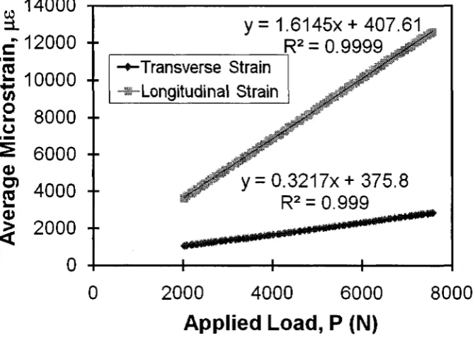
4.3 Strain Distribution 76 4.3.1 Longitudinal Strain Distribution 76
4.3.2 Transverse Strain Distribution 88 4.4 Average Bond Stress versus Average Bond Slip 91
4.5 Average Bond Stress versus Normalized Load 98
4.6 Average Bond Stress Distribution 108
4.7 Average Bond Strength 116 4.7.1 Average Bond Strength versus Bonded Length 117
4.7.2 Average Bond Strength versus Bonded Width 120
4.8 Effective Bond Length 122 4.8.1 Effective Bond Length versus Stiffness 126
4.9 Failure Modes 129 5 SUMMARY, CONCLUSIONS AND RECOMMENDATIONS 134
APPENDIX B - TRANSVERSE STRAIN VERSUS GAUGE DISTANCE 160
APPENDIX C - LOAD VERSUS DISPLACEMENT 162 APPENDIX D - AVERAGE STRESS VERSUS AVERAGE SLIP 179
APPENDIX E - AVERAGE STRESS VERSUS RELATIVE LOAD 195 APPENDIX F - AVERAGE STRESS VERSUS GAUGE DISTANCE 211
LIST OF TABLES
Table 2.1-Physical Properties of CFRP Products 10
Table 3.1 -Parameters 33 Table 3.2 - Fine Aggregates Selection (CSA A23.1 M90 1990) 34
Table 3.3 - Fine Aggregate Results (Batch #1) 35 Table 3.4 - Fine Aggregate Results (Batch #2) 35 Table 3.5 - Fine Aggregate Results (Batch #3) 36 Table 3.6 - Coarse Aggregates Selection (CSA A23.1 M90 1990) 36
Table 3.7 - Coarse Aggregate Results (Batch #1) 37 Table 3.8 - Coarse Aggregate Results (Batch #2) 37 Table 3.9 - Coarse Aggregate Results (Batch #3) 38
Table 3.10 - Coupon Dimensions 41
Table 3.11-Slump Values 1 Table 3.12 - Seven-Day Compression Strength Values 1
Table 3.13 - 28-Day Compression Strength Values 1 Table 4.1(a) - Test Matrix and Test Results for Group 1 1 Table 4.1(b) - Test Matrix and Test Results for Group 2 1 Table 4.1(c) - Test Matrix and Test Results for Group 3 1 Table 4.1(d) - Test Matrix and Test Results for Group 4 1 Table 4.2 - Load versus Displacement Data for the Control Specimens 1
Table 4.3 - Specimen Groups Details 77 Table 4.4-Strain Distribution Data for L350W100L1RW1 1
Table 4.5-Strain Distribution Data for L350W75L1RW1 1 Table 4.6-Strain Distribution Data for L350W100L1SW1 1 Table 4.7 - Transverse Strain Distribution Data for L450W75L1SW2 1
Table 4.8 - Average Bond Stress versus Normalized Load Data for L450W100L2SW2 1
Table 4.9 - Average Bond Stress Distribution for L450W100L1SW2 1 Table 4.10 - Data for the Average Bond Strength versus Bonded Length Relationship for (a)
W100 (One Layer), and (b) W100 (Two Layers) 1 Table 4.11 - Data for the Average Bond Strength versus Bonded Length Relationship for
(a) W75 (One Layer), and (b) W75 (Two Layers) 1 Table 4.12 - Data for the Average Bond Strength versus Bonded Width Relationship for
LIST OF FIGURES
Figure 2.1 - Hand Lay-up Process Figure 2.2 - Pultrusion Process
Figure 2.3 - Filament Winding Process
Figure 2.4 - Shear Strengthening Case for Interface Debonding Failure Figure 2.5 - Flexural Strengthening Case for Interface Debonding Failure Figure 2.6 - CFRP Anchor (a) before Installation & (b) after Installation Figure 2.7 - Direct Tension Test
Figure 2.8 - Three-Point Bending Test Figure 2.9 - Wedge Splitting Test
Figure 2.10 - Shear Bond Test Methods: (a) Single-Lap, (b) Double-Lap, and (c) Bending Type Figure 2.11 - Beam-Type Dowel Test
Figure 2.12 - Slab-Type Dowel Test
Figure 3.1 - Tension Test Specimen Drawing Figure 3.2 - Coupon Dimensions
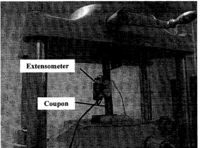
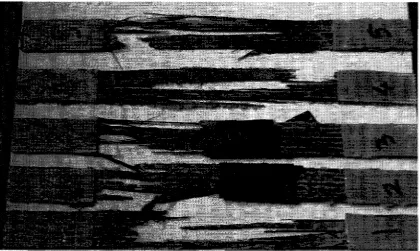
Figure 3.3 - Coupon Test Set-up Figure 3.4 - Coupon Failure Figure 3.5 - Load vs. Strain
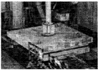
Figure 3.6 - Top View of Form (All Dimensions in mm) Figure 3.7 - Compression Test Failure
Figure 3.8 - Surface Preparation Figure 3.9 - Detail of Rounded Corner Figure 3.10 - Application of Primer
Figure 3.11 - Impregnating the CFRP Sheet Figure 3.12 - Technique of Applying Roller
Figure 3.13 - Saturation of CFRP Sheet on Specimen Figure 3.14 - Specimen L450W100 Layout
Figure 3.15 - Specimen L350W75 Layout
Figure 3.16- Strain Gauge Locations (All Dimensions in mm) Figure 3.17 - Strain Gauges Installed in Transverse Direction Figure 3.18 - LVDT Location on the Specimen
Figure 3.19 - Tinius Olsen Machine Controller Figure 3.20 - Test Set-up
Figure 3.21 - CFRP Debonding
Figure 4.1 - LVDT Location (All Dimensions in mm)
Figure 4.2 - Load vs. Displacement for the Control Specimens
Figure 4.6 - Load versus Displacement for L350W100L1SW2 and L350W100L1RW2 Figure 4.7 - Load versus Displacement for L350W75L1RW1 and L350W75L1RW2 Figure 4.8 - Strain versus Gauge Distance for Group 1
Figure 4.9 - Strain versus Gauge Distance for Group 2 Figure 4.10 - Strain versus Gauge Distance for Group 3 Figure 4.11 - Strain versus Gauge Distance for Group 4
Figure 4.12 - Strain versus Gauge Distance for L350W100L1RW1 Figure 4.13 - Strain versus Gauge Distance for L350W75L1RW1 Figure 4.14 - Strain versus Gauge Distance for L450W100L1RW2 Figure 4.15 - Strain versus Gauge Distance for L450W75L1SW1 Figure 4.16 - Strain vs. Gauge Distance for L450W75L2SW1 Figure 4.17 - Strain versus Gauge Distance for L350W100L1SW1 Figure 4.18 - Strain versus Gauge Distance for L450W75L1RW1 Figure 4.19 - Strain versus Gauge Distance for L450W75L1RW2 Figure 4.20 - Transverse Strain Distribution for L450W100L1SW2 Figure 4.21 - Transverse Strain Distribution for L450W75L1SW2 Figure 4.22 - Transverse Strain Distribution for L350W100L1SW2 Figure 4.23 - Transverse Strain Distribution for L350W75L1SW2
Figure 4.24 - Example of Average Bond Stress versus Average Bond Slip
Figure 4.25 - Average Bond Stress versus Average Bond Slip Curves for Specimens with Different Stiffness
Figure 4.26 - Average Bond Stress versus Average Bond Slip Curves for Specimens with Different Bond Lengths
Figure 4.27 - Average Bond Stress versus Average Bond Slip Curves for Specimens with Different Bond Width
Figure 4.28 - Average Bond Stress versus Average Bond Slip Curves for Specimens with Different Surface Preparations
Figure 4.29 - Average Bond Stress versus Average Bond Slip Curves for Specimens with Different Cross Wrap Locations
Figure 4.30 - Average Bond Stress as a Function of Normalized Load
Figure 4.41 - Example of Average Bond Stress Distribution
Figure 4.42 - Average Bond Stress Distribution for L350W75L1SW1 Figure 4.43 - Average Bond Stress Distribution for L350W75L2SW1 Figure 4.44 - Average Bond Stress Distribution for L450W100L2RW1 Figure 4.45 - Average Bond Stress Distribution for L350W75L2SW1 Figure 4.46 -Average Bond Stress Distribution for L450W100L1RW2 Figure 4.47-Average Bond Stress Distribution for L450W75L1RW2 Figure 4.48 -Average Bond Stress Distribution for L350W75L2RW1 Figure 4.49 -Average Bond Stress Distribution for L450W100L2SW1 Figure 4.50 -Average Bond Stress Distribution for L450W100L2SW2 Figure 4.51 - Fracture Energy, Gf
Figure 4.52 - Gf for a Stress-Strain Linear Relationship
Figure 4.53 - Effective Bond Length versus Stiffness for Specimens with a Bond Length of 450 mm and a Bond Width of 100 mm
Figure 4.54 - Effective Bond Length versus Stiffness for Specimens with a Bond Length of 450 mm and a Bond Width of 75 mm
Figure 4.55 - Debonding at the Lower Part of the Specimen Figure 4.56 - Debonding at the Upper Part of the Specimen
CHAPTER 1 INTRODUCTION
1.1 General
Even though steel, masonry, and concrete have served the civil engineering society satisfactorily for a long time, most of the existing infrastructure in Canada, the United States, Europe, and other developed countries are in urgent need of repair or replacement. The main cause to these problems is the corrosion of reinforcing steel inside the concrete, which results in delamination or concrete spalling, loss of steel reinforcement, and failure in some instances (ISIS Canada, 2004). Fiber Reinforced Polymers (FRP) materials have emerged as proficient alternative repair solution.
FRPs have already been used in the aerospace, aeronautical, and automotive industries for decades. They can be modified to take various forms and shapes. In addition, they are not permeable to electromagnetic waves and are very light in weight. They have a high strength-to-weight ratio, do not corrode, and have a tremendous fatigue resistance. Even though the initial cost of FRPs can be very high, they can be deemed to offer an economical solution in new construction projects when the cost of a structure is calculated over its entire life cycle because of their improved durability and significantly lower maintenance cost.
1.2 Statement of Problem
bond length, and the bond width are the principal parameters that would affect the concrete-CFRP interface behaviour. Less attention is drawn to the effect of surface preparation and the amount and location of cross wraps. It is important to observe the influence of the concrete surface preparation since it affects the load transfer mechanisms. Further, it is well known that the main task of cross wraps is to prevent debonding from taking place in a desired area. Therefore, the amount of cross wraps certainly plays an important role in the behaviour of the concrete-CFRP interface.
Another significant issue is that high shear stress concentrations are generated at the end of the externally bonded reinforcement where the forces have to be transferred between FRP and concrete. Therefore, it is of great importance to determine the effective bond length of FRP materials. Researchers have come up with a many estimations for the effective bond length needed to achieve the bond strength capacity. For instance, De Lorenzis et al. (2001) concluded that the effective bond length is 93 mm, whereas Horiguchi and Saeki (1997) obtained a value of 75 mm. Ueda et al. (1998), on the other hand, stated that the effective bond length is less than 100 mm. Sato et al. (2001) found that that value is between 100 mm and 200 mm. A reliable value must be achieved in order to have a safe design.
1.3 Objectives and Scopes
This study was conducted in order to identify the various parameters that play a major role in affecting the bond strength capacity. Consequently, the primary objectives of this research are:
(1) To determine the influence of CFRP's stiffness, CFRP length, CFRP width, surface preparation, and location of cross wraps on the concrete-CFRP interface.
(2) To determine the effective length required to achieve the bond strength capacity. (3) To study shear transfer between concrete and CFRP.
1.4 Contents and Organization
This thesis is divided into five chapters:
Chapter 1 is the introduction.
Chapter 2 summarizes findings accomplished by other researchers relevant to the topic studied,
such as previous studies on the history of FRP's application, concrete-CFRP interface behaviour under different testing methods, and determination of the effective bond length.
Chapter 3 discusses the properties of all materials and instrumentation used. It also describes in
details the experimental program that was performed in acquiring the required data.
Chapter 4 focuses on the analysis of the concrete-CFRP interface response. The effective bond
length is also determined in that chapter.
CHAPTER 2 LITERATURE REVIEW
2.1 General
FRPs can be defined as being a subgroup of composites. Composites, on the other hand, are obtained by combining two or more materials at a macroscopic level to form a new material that has different but better properties than the combined materials. For FRPs, the composite consists of high strength fibers entrenched in a polymer matrix (also known as resin).
Resin's Properties:
The resin is congruent with the fibers both chemically and thermally. Its major task is to bind the fibers together, protect them from harsh environments, and transmit load from one fiber to an adjacent fiber. If a fiber breaks, the resin will not only transfer the load to an adjacent fiber, but to several others as well. This will prohibit further fiber failure and weakening of the composite. There are three types of resins used in composites in infrastructure: polyesters, vinylesters, and epoxies. Polyesters are the most popular in the manufacture of infrastructure composites.
Fibers' Properties:
2.2 Applications of FRPs
The use of FRP materials for structures has been increasing. To date, there are various infrastructure-related field applications of FRPs around the world. The ones that gained the most attention can be divided into the following categories:
- Externally bonded FRP used for maintenance and rehabilitation; - FRP used for internal reinforcement of concrete;
Structures made of FRP hybrid, - Structures that are all-FRP; and
FRP used in seismic retrofitting, especially in retrofitting hollow bridge piers.
2.2.1 Externally Bonded FRP
One of the earliest applications of FRP involved the repair of concrete structures externally with FRP composites. Since they have been very effective in improving the strength of already-built members with minor problems, thousands of installations of this type have been accomplished worldwide. External FRPs have also been used to increase the shear capacity of concrete structures. These composites were aimed at controlling cracks as well. During the last two decades, various repairs have appeared with concrete, metallic, masonry and timber structures.
Concrete Structures: Carbon FRP sheets can be applied to a circular concrete column
that needs to be strengthened. In addition, concrete bridge girders are fortified in shear with externally bonded carbon FRP sheets (ISIS Canada, 2004). Commonly, FRP plates are attached to the tension face of flexural elements to enhance their bending capacity, or to their side to amplify their shear capacity.
Metallic Structures: FRP sheets or wraps are generally bonded to the exterior of
Masonry Structures: Both the strength and ductility for in-plane and out-of-plane shear and
flexural behaviour of masonry walls and columns can be enhanced by using external FRP reinforcements.
Timber Structures: Flexural capacity of a beam or girder is increased by externally bonding
FRP to timber structures. In this case, FRP plates or sheets are connected to the exterior of the timber member using a structural adhesive.
One of the first implementations of this technique was performed in the county of Lacerne, Switzerland. The Ibach Bridge was erected in 1969. It spanned 228 m, and was designed as a continuous multi-span box beam (Meier, 1995). Due to the installation of new traffic signals, some of the prestressing was damaged. Although the unit weight price of CFRP exceeds that of steel significantly, it was chosen for the rehabilitations. Only 6.2 kg of CFRP was sufficient for rehabilitation rather than 175 kg that might be necessary of steel. Additionally, CFRP's lightweight precluded utilizing expensive falsework since all tasks were performed from a mobile platform.
2.2.2 Internal FRPs
The Bishop Grandin Boulevard is a four-lane divided highway that was constructed in 1998. It represents the first Canadian experience of using FRP dowels in concrete pavements. Approximately 27,000 vehicles per day travel on this pavement section with 10% truck traffic (Shalaby and Murison, 2001), and so far no pavement crisis have been declared.
2.2.3 Hybrid Structures
Since FRP composites have a higher initial cost, a number of hybrid systems have been recently constructed. Hybrid systems have demonstrated to be very effective since they combine the high stiffness and high compression strength of conventional materials. Most of the structures being utilized are the hybrid FRP/concrete structural systems. These systems are best designed by placing the FRP composites where its high tensile strength can be exploited, while taking advantage of the high compressive strength of concrete. Moreover, FRP hybrids are very beneficial because they can be very light, and the fact that no corrosion is expected to take place makes them maintenance-free. These types can be used as stay-in-place form work, concrete-filled FRP piles and/or girders for bridges, and as supporting elements in buildings.
In Canada, FRP was first utilized in the Beddington Trail Bridge located in Calgary, Alberta (Tennyson et al, 2001). The bridge is composed of two spans containing 13 bulb-T girders each. Out of the twenty six girders, six were prestressed using FRP tendons. The bridge was open to traffic in 1993. A system of structurally integrated optical sensors was installed to monitor the behaviour of the bridge.
2.2.4 All-FRP Structures
structures such as parking garage stairwells, pedestrian bridges, short-span road bridges and utility poles can be built purely from FRPs.
FRP prestressing tendons have been used in the Notsch Bridge in Austria, and the Ulenberg Bridge in Germany. In Ohio, FRP rods were employed in the re-decking of the Salem Avenue Bridge, and in the construction of the Pierce Street Bridge (Uomoto et ah, 2002).
2.2.5 Seismic Retrofitting
The primary application for seismic retrofitting is column wrapping. It can replace steel jackets and provide additional confinement for the column. That in turn, provides additional ductility to the column and allows rebar splices with inadequate laps to be more fully developed. Most masonry walls are not connected to each other correctly making them vulnerable under seismic events. The major problem is that most of the times, the walls orthogonal to the direction of earthquakes collapse following out-of-plane mechanism. Encasement of masonry structures of FRP shells may improve their strength and ductility tremendously hence solving this problem.
The Portage Creek Bridge in Victoria, British Columbia was built in 1982 prior to current seismic design codes and would not comply with the current standards' requirements with regards to potential earthquake forces (Mufti, 2002). It was decided that FRP wraps should be used to strengthen the short columns, which would potentially fail in catastrophic shear during a large earthquake.
2.3 Introduction to Carbon Fibers
molecular composition. The carbon layers can smoothly slide pertaining to each other since the bonding between them is Van der Waal bonding (Chung, 1994). The properties of the carbon fibers vary broadly depending on the structure of the fibers.
Commercial carbon fibers are acquired from three sources:
(1) Pitch, a by-product of petroleum distillation that is passed through a thin nozzle and stabilized by heating,
(2) PAN (PolyAcroloNitrile), which is carbonized through burning, and (3) Rayon.
Both rayon and isotropic pitch are useful for fabricating low modulus carbon fibers. PAN and liquid crystalline pitch are utilized in higher modulus carbon fibers.
Carbon fibers are classified as either high modulus Type I or high strength Type II. These types differ in properties due to the disparities in fiber microstructure. The arrangement of the hexagonal layer networks available in graphite is responsible for the differences. For instance, the material would be classified as graphite if those layers are organized in three-dimensional stacks. If, on the other hand, the layers are arranged two-three-dimensionally and the bonding is weak, the material would be defined as carbon.
Even though carbon fibers are more expensive than glass fibers, they are currently being preferred in structural engineering applications, especially for repair and strengthening of reinforced concrete beams, columns and slabs. Their attractiveness is derived from their low density, exceptional resistance to thermal (low thermal expansion coefficient), chemical and environmental effects, high tensile modulus and regularly decreasing cost.
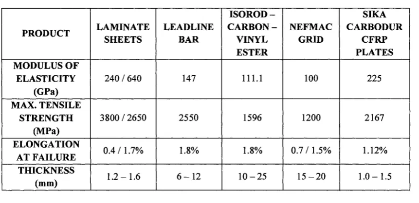
2.3.1 CFRP Products
Table 2.1 - Physical Properties of CFRP Products PRODUCT MODULUS OF ELASTICITY (GPa) MAX. TENSILE STRENGTH (MPa) ELONGATION AT FAILURE THICKNESS (mm) LAMINATE SHEETS
240 / 640
3800/2650 0.4/1.7% 1.2-1.6 LEADLINE BAR 147 2550 1.8%
6 - 1 2
I S O R O D - CARBON-VINYL ESTER 111.1 1596 1.8%
1 0 - 2 5
NEFMAC GRID
100
1200
0.7/1.5%
1 5 - 2 0
SIKA CARBODUR CFRP PLATES 225 2167 1.12% 1.0-1.5 Laminate Sheets
Laminates, which are the most common forms of composites in structural applications, are created by stacking various thin layers of fibers and matrix and joining them. Several physical and mechanical properties can be achieved depending on the stacking layout and the fiber orientation in each layer.
Laminate sheets are high strength, pre-manufactured carbon/epoxy laminates. They are used for surface mounted or near surface mounted applications adding strength and stiffness to concrete or masonry structures. Both paste and liquid epoxy resins aid these laminates in bonding to concrete and providing a light weight, non-corrosive material that is easy to install (ISIS Canada, 2004).
LEADLINE Bar
It is a type of carbon FRP pre-stressing (pre and post-tensioning) bar fabricated by
Mitsubishi Chemical with their coal tar pitch fiber materials. It has been used mainly in Japan
ISOROD-Carbon-Vinyl Ester Reinforcing Bar
It is made of continuous longitudinal E-glass fibers joined together with a polyester resin. Pultrusion is again used here, and the outcome is a bar with a smooth surface that can be distorted with a helical twisting of identical fibers. The CFRP reinforcing bars behave elastically and linearly up to failure in tension. They demonstrate brittle tensile failure mode (ISIS Canada, 2004).
NEFMAC Grid
New Fiber Composite Material for Advanced Concrete grid is a two-dimensional reinforcement made of high performance fibers such as glass and carbon impregnated with resin. It is mostly used in offshore construction, bridge decks, tunnel lining applications, and light-weight curtain walls in buildings. Besides being corrosion resistant, NEFMAC facilitates good stress transfer since the intersections offer anchorage and mechanical interlock in the concrete. Pin-winding, which is a process similar to filament winding (explained later in this chapter) is performed in fabricating this grid as flat or curved (ISIS Canada, 2004).
CFRP Plates
CFRP Plates can be bonded to the exterior of concrete structures using high-strength adhesives to provide additional reinforcement to that provided by internal reinforcing steel. They have the advantage of being easy to handle because of their light-weight, corrosion resistance, and high strength. Their mechanical properties in the longitudinal direction are almost exclusively controlled by the fibers. What is really great about them is that they have long fatigue life. Commercially available CFRP plates consist of 60 to 70% by volume of unidirectional carbon fibers of approximately 10 urn diameter (Almakt et al, 1998). The most popular manufacturer of CFRP plates in Canada is Sika Canada Inc.
applying the adhesive. It has been found that adhesion to exposed aggregates is better than to hardened cement paste (Sato et ah, 2001). The advantage of using adhesives rather than anchorages such as bolted connections is that the former generates distributed stress over the entire contact interface, whereas the latter produces concentrated stress.
Epoxies, the most popular adhesives in structural applications, are used mainly for producing high performance composites with advanced mechanical properties, corrosion resistance, good adhesion to a substrate and superior electrical properties. In general, epoxies cured with heat will be more heat-resistant than those cured at room temperature. Epoxy resins are utilized with various fibrous reinforcing materials, including glass, carbon, and aramid.
2.3.3 Carbon Fiber Processing Methods
There are various methods of composite processing that are utilized. Only three of them are relevant in fabricating structural components.
Hand Lay-up (Wet Lay-up)
Dry unidirectional fiber sheets with the fiber running in one planar direction,
Dry multidirectional fiber sheets or fabrics with fibers oriented in at least two planar directions, and
Dry fiber tows wound or mechanically applied to the concrete surface. They are impregnated with resin during the winding operation.
The following steps illustrate the installation process (Figure 2.1)
Prepare Substrate: The concrete must be properly prepared before bonding. No spalling or delamination should be present, and the corners must be ground to a minimum radius of 10 mm (Horiguchi and Saeki, 1997). Any unevenness in the concrete is usually removed with a mineral-based re-profiling mortar.
Prime Concrete: Some systems require that the clean surface be coated with a primer. Apply Epoxy: The adhesive is applied to the front and back of the material using a roller or brush in order to saturate the sheet and ease installation. Once that is done, the material may be rolled to facilitate transport.
Place FRP Sheet on Structure: Unfold the sheet rolls onto the structural element being strengthened. Placing one roll at a time, pressure should be applied to the wrap using a hard rubber roller with ridges.
Apply Epoxy to Sheet Surface: To fully saturate the material, a topcoat of epoxy should be added on the surface.
Pultrusion
FRP bars, rods, tendons, plates, I-beams, prestressing strands and twisted cables are produced by using pultrusion. It is a technique that is fully automated and hence, very economical. This process is done by hauling untreated fibers through a resin bath and then through a heated die. At this stage, the polymer matrix takes the form of the die, and the structural component is produced (Figure 2.2)
i teAitfyfMroftMtn
M*Hi*em*:0(J
c*%**oiiNra t u i E
c
CAHT-OfF S ^ W
Figure 2.2 - Pultrusion Process (Alma Memo Series, 1995)
Filament Winding
It is primarily used for hollow, circular or oval sectioned components like poles, pipes, and tubes. In this method, fibers are drawn off single or multiple continuous fiber spools through a resin bath before being wound into a rotating mandrel to produce the desired shape (Figure 2.3). The temperature of the mandrel, the impregnation temperature of the resin, the impregnation time, the tension of the fibers, and the pressure of the fiber winding are processing parameters that need to be controlled. The main advantage of filament winding is its high processing speed, which results in a low cost.
HW « * T EWE
I M M B M * CAHHIAOe
s~\
m-SIH IMMMMMYKM
vmm 8M)OI.3
2.4 Behaviour of RC Beams Strengthened with CFRP Sheets
One of the most successful technologies for strengthening or stiffening reinforced concrete is the use of externally bonded CFRP material in the form of laminates (sheets) or plates. Plates are connected to the bottom surface of beams to add tensile reinforcement. CFRP sheets provide additional tensile resistance by being attached to the bottom surface or wrapped around the stem of RC rectangular or T-beams by applying epoxy adhesives. RC beams externally strengthened with CFRP laminates have a low overall installation cost because of their light weight, corrosion and alkali resistance and large tensile strength. In addition, this reinforcing technology provides great strength and an excellent fatigue resistance.
In most strengthening cases, the interface bond between CFRP composites and concrete substrates is vital in transmitting stresses from the RC structure to the externally bonded CFRP composites. Hence, a good understanding of that phenomenon is critical in achieving a more consistent design. Plate bonding and sheet bonding are the two interface bonding systems available. CFRP plate bonding systems allow more quality control than sheet bonding, whereas there is a greater potential for construction imperfections with sheet bonding since the curing of the CFRP composites and the mixing of resins are both carried out in the field. Sheet bonding systems' popularity originates from their high flexibility and convenience for construction. They are mostly utilized in flexural and shear strengthening where debonding of the CFRP from concrete substrate can lead to overall structural failures (Figures 2.4 and 2.5).
. * *
Debonding failure ^ D e b o n d i n g failure around anchorage mm arop.nd mid-span area
Figure 2.5 - Flexural Strengthening Case for Interface Debonding Failure (Ueda and Dai, 2005)
2.5 Ductility
Ductility is needed since it offers warning for any forthcoming failures. Usual design ensures that failure of RC beams initiates by some cracking of concrete in tension followed by yielding of steel reinforcement. After extensive deformation at no considerable loss of load carrying capacity, concrete cracking, and ultimate failure take place.
External strengthening analysis of RC beams with CFRP is based on Bernoulli's hypothesis of strain compatibility that plane sections remain plane. This necessitates absolute bonding between concrete and CFRP and the capability of stresses to be transmitted by the concrete to the CFRP laminate by shear. Absolute bonding assumption requires that:
1. Sufficient anchorage and development length is warranted for the CFRP reinforcement. 2. CFRPs are linear elastic up to failure
3. In most cases, initial strains in the section at the time of strengthening can be ignored 4. Concrete compressive stress-strain curve is parabolic. Furthermore, concrete is assumed
to have no strength in tension.
happens abruptly. Failure can be due to CFRP debonding, rupturing of CFRP sheets or concrete crushing. In the last two modes of failure, the ultimate strength of the structural member can be easily predicted by following conventional RC flexural theory. When it comes to CFRP debonding, however, the strengthened member is not able to reach its ultimate strength; hence, the prediction of that type of failure is not an easy task.
It might be difficult to fulfill ductility requirements, since if the design is controlled by the "Serviceability Limit State", the amount of FRP provided to a structure may be larger than that required by the "Ultimate Limit State" (Triantafillou et ah, 2001). The Canadian Highway Bridge Design Code (2000), based on the work of Jaeger et ah (1997), evaluates the deformation index of FRP strengthened beams with the following performance factor:
(M„Oj/(M,0 1O,0 1) (2.1)
Where M is the beam's moment, O is the curvature. The subscript "u" refers to the ultimate state, whereas ".001" defines the service state that corresponds to a concrete maximum compressive strain of 0.001. This performance factor is usually greater than 4 for a rectangular beam and greater than 6 for a T-section.
2.6 Flexural Strengthening
block as suggested in CSA A23.3 for reinforced concrete buildings, and in CSA S6 for concrete bridges (ISIS Canada, 2004). In addition, CSA S806-02 (2002) offers all design guidelines and test methods available for the design and construction of building components with FRP.
In Flexural strengthening applications, CFRP composites are connected to the tensile surface of the reinforced concrete beams. For this type of strengthening, it is assumed that CFRP materials are perfectly linear elastic. Hence, failure in such a situation would be due to CFRP rupture, concrete crushing, or delamination. To calculate the ultimate flexural strength in either of these modes, a similar technique as that used for steel reinforced sections is followed.
Meier (1987) reported the use of thin CFRP sheets as flexural strengthening reinforcement of concrete beams. He proved that steel plates can be replaced with CFRP with an overall cost savings as high as 25%.
Plevris (1995) investigated the flexure behaviour of concrete beams strengthened with CFRP sheets. The most significant variables affecting the member strength were found to be the concrete strength, CFRP failure strain, and CFRP's length to width ratio. Based on the results, it was concluded that, except for the cross section dimensions, the effects of the laminate's length, and the initial strain, all other variables including the ratio of live to dead load are equally important on reliability against flexural failure.
flexural strength increased up to 58% on concrete beams strengthened with anchored CFRP sheets.
2.6.1 Plate-End Failure
Many studies have been performed on the mechanisms of the plate-end failure because of its catastrophic results (Sebastian, 2001). This type of failure is very brittle and is generated due to high concentrations of shear and normal stresses happening at the end of CFRP near supports. The main factors that influence this type of failure are the distance between the ends of the CFRP and the beam supports and the usage of fairly thick CFRP plates. Thus, this is not a concern for CFRP sheet bonding systems since they are usually extended to the support.
2.6.2 Anchorage Failure
Also known as debonding and is due to insufficient anchorage length of CFRP sheets. Anchorage failure of CFRP is usually noticed in beams strengthened for flexure with CFRP, which usually debonds at about half of its ultimate strain. That is most often caused by the weakness of the concrete substrate rather than in the epoxy.
Since the effective bond length has been reported in a wide range by different researchers, it becomes important to come up with some sort of approach where the anchorage length can be acquired based on the bond stress-slip relationship. By developing a model, the anchorage length of CFRP sheet-concrete interfaces can be determined by analyzing the strain distributions in CFRP sheets and the bond stress distributions along the interface. The effective bond length is defined as the active bond length, Le, and is formulated as the following:
JilE ft f ( \ + a\
L
e=
V±1 In f±-5L (2.2)
constantly exists an infinitesimal shear stress between the CFRP and concrete. Based on experiments, factor a can be taken as 0.96 for anchorage designs (Dai, 2003).
The bond strength for CFRP sheet-concrete interfaces can be expressed as follows:
Pu = aPn (2.3)
exp LbB4Gf
a = • { pEfff )
exp
h
B4
Gf
\W^t)
+ i(2.4)
P^-(bf+2Abf\j2EftfGf (2.5)
where Pu is the bond strength of CFRP sheet-concrete interface with a given bond length Lb,
Lb is the bond length of CFRP sheets, Abf is an additional width that can be taken as 3.7 mm
based on test results (Sato et al, 2001).
The large distribution of bond strength is another concern. Even though a standard concrete surface treatment is followed, the bond strength of CFRP sheets-concrete interfaces is very sensitive to the condition of concrete surface preparation. That is because the bond failure takes place within a thin concrete layer just underneath the adhesive all the time, and the conditions are affected by the skills of the workers.
2.6.3 Mid-Span Debonding
It is also connected to crack spacing, dowel action on the CFRP sheets, and the bond between the concrete and steel reinforcement. Mid-span debonding guidelines attempt to avoid it by recommending limits on the strains in the CFRP sheets.
2.7 Shear Strengthening
CFRP shear reinforcement may be continuous sheets or strips in finite width. Externally-bonded CFRP shear reinforcement's behaviour resembles the internal steel stirrups in that bridging shear cracks enhances the shear capacity of the concrete.
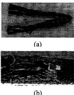
Since the height of the beam limits the length over which CFRP reinforcement can be anchored, the quality of the existing concrete is vital. Also, it is required in some cases to add a longitudinal CFRP shear anchorage strip to improve anchorage of the external shear reinforcement (Figure 2.6). In order for potential failure of CFRP sheets caused by stress concentrations at the corners of the beam to be prevented, corners should be rounded to a minimum radius of 1 5mm (ISIS, 2004).
(b)
Figure 2.6 - CFRP Anchor (a) before Installation & (b) after Installation (Kim, 2006)
related to the bond mechanism, and is more applicable to the CFRP systems that do not close around the entire cross section. The lower of the two results is taken as the shear strength contribution of the CFRP reinforcement.
2.8 Combination of Shear and Tension
The main attributing failure when a combination of shear and tension is considered is the "Block Shear" or "Cleavage Failure". It is associated with laminates having insufficient cross wraps or inadequate edge distance. For this type of failure, a crack parallel to the applied load starts at the edge of composite and propagates toward the bolt hole. This causes the commencement of other cracks across the net section due to the formation of in-plane stresses.
RC beams externally strengthened with CFRP in flexure can originate another mix-mode failure (combination of shear and tension). The interface debonding may commence from the tip of a shear-flexural crack. In that case, the peeling is generated by crack opening in longitudinal direction as well as crack sliding in the vertical direction. The latter is difficult to measure during experimental tests of RC beams flexurally strengthened with CFRP sheets. Shear strengthening with transverse strips limits the diagonal cracking, which may restrain this type of failure.
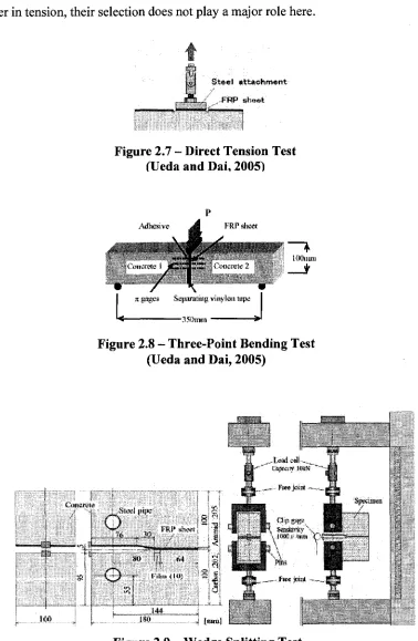
2.9 Bond of CFRP Sheet-Concrete Interfaces under Tension
fatigue loading. Since adhesives have a greater effect on the CFRP sheet-concrete interface in
shear rather in tension, their selection does not play a major role here.
f?
e S t e e l a t t a c h m e n t
FRP s h e e t
Figure 2.7 - Direct Tension Test fUeda and Dai, 2005)
Adhesive FRP sheet
it fftges Separating vinylou Jape
^ 35Bmjii ** lOQuun
Figure 2.8 - Three-Point Bending Test (Ueda and Dai, 2005)
: Conerew
..Sire! itipc
o
76 _ . M . rap
XV l-'_ U -\~y r f'iim(iu)
31
V-H
Sacfenitv •,
I « I i » t T
2.9.1 Anchorage Design for Tensile Force in CFRP Sheets
The bond of externally bonded CFRP sheets to concrete differs from that of reinforcing bars in concrete (Ueda and Dai, 2005). Usually, the anchorage design criteria for the bond of reinforcing bars in RC beams is to assure an adequate development length that would aid the reinforcing bar to resist a tensile force equivalent to its tensile strength. The externally bonded CFRP sheets, however, don't usually reach their material strength even over a very long bond length. This is due to the presence of premature debonding and effective bond length. Various models have been proposed up to date where only the effects of CFRP stiffness and concrete strength are considered. In most available models, the effective bond length is utilized to predict the bond strength of a CFRP sheet-concrete interface by determining if its bond length is longer than the effective bond length.
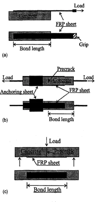
2.10 Bond of CFRP Sheet-Concrete Interfaces under Shear
The main task of the bond interface between CFRP sheets and concrete is the transfer of shear stresses from the concrete structure to externally bonded CFRP sheets for shear and flexural strengthening. Test methods include single-lap, double-lap, bending and inserted type (Figure 2.10). Using these methods, the strain distribution in the CFRP sheets have been studied to illustrate the local interfacial shear bond behaviour. Further, interface characteristic parameters such as the average shear bond strength, effective bond length, maximum shear bond stress, interfacial fracture energy, and the local bond stress-slip relationship have been evaluated (Ueda and Dai, 2005).
Load
\ FRP sheet
^^j|^B||i^w^f^B^Bj|f!!U^^^^^^^^^^^^*^
Bond length Grip
(a)
Load
Precrack
Bond length
(c)
1
I Load
mmmmmmgmmmmm
{ \FRP sheet f
Bond length
Figure 2.10 - Shear Bond Test Methods: (a) Single-Lap, (b) Double-Lap, and (c) Bending Type
(Niu and Wu, 2006)
Yoshizawa et al. (1996) studied the effect of concrete surface preparation on the bond behaviour. The specimen was tested in tension producing direct shear on the sheets. Sandblasting and water jet were both used for surface preparation. It was reported that, in comparison to sandblasting, the water jet doubled the capacity of the specimen. The bonded length of the CFRP sheet, however, did not affect the ultimate load significantly.
not agree with other researchers' findings. Nonetheless, they did mention that the effect of bonded length diminishes at longer lengths. It was found that the critical bond length is at least larger than 275 mm.
Horiguchi and Saeki (1997) studied the effect of test method and quality of concrete on the bond of CFRP sheets. They examined the outcome of three different test methods, shear test, flexural test, and direct tensile test.
For the shear test, two concrete specimens were used with rectangular cross-sections of 100 mm wide, 100 mm high, and 200 mm long. The specimens were bonded with carbon sheets on each side.
Two concrete specimens with rectangular cross-sections of 150 mm wide, 150 mm high, and 200 mm long were prepared for the bending test. A carbon sheet was attached on the tension side of these specimens.
For the tensile test, the bond strength between the CFRP sheet and the concrete surface was determined by the ultimate tensile force divided by the bonding area of 40 mm x 40 mm.
Out of the three tests, the tensile test generated the largest average bond strength, and the bending test ranged second. The lowest bond strength was obtained in the shear test. In instances of low compressive strength, however, the three test results were converged at certain level.
Maeda et al. (1997) examined the bond mechanism of CFRP sheets. Test results illustrated that the ultimate load increases as the stiffness of the fiber sheet increases. The maximum load did not vary for bonded lengths above approximately 100 mm. This outcome proved the existence of an effective bond length that is less than 100 mm.
experimental results, it was concluded that the bond strength does not increase with bond length longer than 100 mm. As CFS stiffness increases, the maximum local and average bond stresses at delamination increase, and CFS strain gradient decreases. CFS with a narrower width has bond strength greater than a wider width. An equation to predict the maximum local bond stress was suggested based on the observed bond stress in CFS.
Bizindavyi and Neale (1999) presented a new experimental apparatus designed and constructed at the University of Sherbrooke, Canada. The test system consisted of an FRP laminate bonded to a concrete block, which is then placed into a tensile loading frame. The assembly was designed so that there is direct shear at the composite-to-concrete interface. From the tests, full tensile capacity of the bonded composites could develop for both one and two-ply CFRP and GFRP laminates. For a one and two-ply 25 mm wide CFRP-to-concrete joints, bond lengths of 80 mm and 220 mm, respectively, were adequate to reach the full capacity of the composites. However, these findings are only applicable for the composite systems used in this investigation.
Brozens and Van Gemert (1999) carried out a series of twenty four direct shear tests. The test specimens consisted of two concrete prisms (150 mm x 150 mm x 300 mm) bonded together with one, two, or three plies of CFRP sheets at two opposite sides. On the other two sides, steel plates were glued to initiate the tensile force. They tested two CFRP widths, 80 mm and 120 mm, and two bonded lengths (the length on one prism, which is half of the total CFRP length), 150 mm, and 200 mm. The main objective of their study was to verify the assumptions, and to check the validity of a non-linear fracture mechanics based design that was set up to describe the occurrences at the end of the externally bonded reinforcement. Results showed that the fracture load of the direct shear test specimens can be very well predicted.
51 mm on each side of midspan. This investigation illustrated that the maximum load is not affected by the bonded length and the concrete strength. Also, the sheet width did not influence the bond strength. The CFRP stiffness affected the bond failure load, but the average of the maximum loads of the two-ply series was only 1.5 times that of the one-ply series. Finally, roughening the surface by chiseling improved the performance of the specimen, and was much better than sandblasting. Failure occurred in the former by rupture of the FRP sheet at a remarkably higher load.
Nakaba et al. (2001) conducted a double-face shear type bond test. The specimen consisted of a prism with a notch at the center, reinforced with FRP laminates on both faces. This research studied the effect of CFRP stiffness, concrete strength (50 and 24 MPa), and influence of putty thickness. Thirty six specimens were tested where the bond length was taken as 300 mm, and the laminate width was 50 mm. Carbon (standard and high stiffness) and aramid fiber were used. To verify the influence of the quality of the substrate, the specimens were made by concrete and mortar. It was concluded that the maximum load increases as the stiffness of FRP increases. The maximum local bond stress was not found to be influenced by the type of FRP, but it increased as the compressive strength of concrete increased.
Kamel et al (2006) presented a study on the interfacial behaviour of CFRP sheets when applied to concrete members as external reinforcement. Two shear test methods were performed using separate test series to examine the bond behaviour and failure mechanism of CFRP sheets bonded to concrete. The first series used modified push-apart specimens, whereas the second series consisted of pull-apart specimens. In both series, the bond length, bond width, and strain distribution were investigated. The anchorage requirements were studied only in the pull-apart specimens.
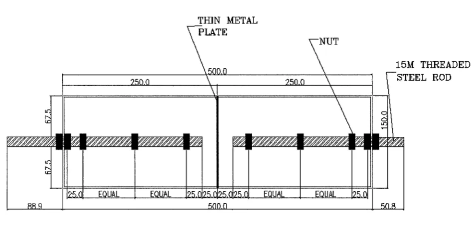
Each specimen in the push-apart series was a rectangular concrete block with a rectangular empty core. Metal sheets were positioned along the width of the specimen arms in their center to force the crack to develop in that location. A rigid steel plate was fixed to the inner face of the specimen to create a flat surface for applying the load.
In the pull-apart test, on the other hand, each specimen was a concrete prism with two embedded concentric steel bars. Metal sheets were placed at mid height to initiate crack when the load was applied. Anchor sheets were bonded on both sides of specimens prepared for studying the anchor sheet effect. Spiral reinforcements were placed around the steel bars to reduce the possibility of any bond slip of the rebars that apply the load to the concrete. Each steel bar was 25 mm in diameter and 500 mm in length, with 250 mm inside the concrete prism.
2.11 Bond of CFRP Sheet-Concrete Interface under Shear and Tension
Since the CFRP sheet-concrete interface experiences both shear and tension, it makes sense to study this combined mode more thoroughly. Karbhari and Engineer (1996) performed a bond test by producing different interface peeling angles. Their main goal was to be able to evaluate both Mode I and Mode II (tension and shear, respectively) components of interfacial fracture energy. They were also hoping to allow a quantitative comparison of interface adhesion mechanisms and energies.
In Japan, a new application of CFRP strengthening has been developed where the CFRP sheets are being bonded on the bottom surface of tunnel linings or elevating bridges (Ueda and Dai, 2005). This technology was created to prohibit weakened concrete blocks from falling. The two types of test methods applied in this case are the beam-type dowel test and the slab-type shear punching test. In the former, one-directional CFRP sheets are bonded on the bottom of a notched concrete beam (Figure 2.11). In the latter, however, bidirectional CFRP sheets are attached on the bottom of a concrete slab (Figure 2.12). The outcome from both test methods is similar. Under the dowel action, the two basic bond characteristics of CFRP sheet-concrete interface are acquired. During the interface debonding procedure,
(1) The peeling angle is constant, and
(2) The maximum vertical force per unit width for CFRP sheet-concrete interface is a constant value.
I
^
concrete beam
! i
FRP sheet
Figure 2.12 - Slab-Type Dowel Test (Ueda and Dai, 2005)
CHAPTER 3
EXPERIMENTAL METHOD
3.1 Introduction
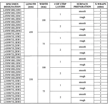
Various studies have been pursued to define and correlate the parameters that can influence the bond behaviour. It is still not clear what variables would affect the behaviour of the concrete-CFRP interface most. In this study, 32 reinforced concrete specimens and two control specimens were tested and test data were analyzed to study shear transfer between CFRP and concrete. The parameters studied included the bond length, bond width, surface preparation, presence of cross-wraps on one or both halves of the specimen, and the stiffness of CFRP. Table 3.1 shows the test matrix used for this study. The specimen designation followed to express the various possible combinations was:
LxxxWxxxLnXWx
where, Lxxx stands for the length of the CFRP sheet in mm. That value varied between 450 mm and 350 mm,
Wxxx stands for the width of the CFRP sheet in mm. Half the specimens had a CFRP width of 100 mm, whereas the other half had a CFRP width of 75 mm,
Ln stands for the number of CFRP layers, which was varied between one layer and two layers,
X stands for the surface preparation (either rough (R) or smooth (S)), and
Table 3.1 - Parameters SPECIMEN DESIGNATION L450W100L1SW1 L450W100L1SW2 L450W100L1RW1 L450W100L1RW2 L450W100L2SW1 L450W100L2SW2 L450W100L2RW1 L450W100L2RW2 L450W75L1SW1 L450W75L1SW2 L450W75L1RW1 L450W75L1RW2 L450W75L2SW1 L450W75L2SW2 L450W75L2RW1 L450W75L2RW2 L350W100L1SW1 L350W100L1SW2 L350W100L1RW1 L350W100L1RW2 L350W100L2SW1 L350W100L2SW2 L350W100L2RW1 L350W100L2RW2 L350W75L1SW1 L350W75L1SW2 L350W75L1RW1 L350W75L1RW2 L350W75L2SW1 L350W75L2SW2 L350W75L2RW1 L350W75L2RW2 LENGTH (mm) 450 350 WIDTH (mm) 100 75 100 75
# OF CFRP LAYERS 1 2 1 2 1 2 1 2 SURFACE PREPARATION smooth rough smooth rough smooth rough smooth rough smooth rough smooth rough smooth rough smooth rough X-WRAPS (sides) 1 2 1 2 1 2 1 2 1 2 1 2 1 2 1 2 1 2 1 2 1 2 1 2 1 2 1 2 1 2 1 2
This chapter discusses the properties of the materials used, the experimental procedure, and the instrumentations used for the experimental study.
3.2 Material Properties
3.2.1 Concrete
The slump chosen for this study was around 200 mm. The nominal maximum size of coarse aggregates was taken as 10 mm, and the 28 day compressive strength was selected to be 30 MPa. No water reducing agent was added. Hence, the by-weight composition of the concrete mixture was as follows:
Water : Cement: Coarse Aggregate : Fine Aggregate = 1 : 1 . 8 5 : 3 . 5 : 4 . 7
3.2.1.1 Sieve Analysis
The sieve analysis was performed according to the requirements of CSA A23.1-M90 (1990) and CSA-23.2-2A (1990).
Fine Aggregates
The CSA A23.1 M90 - Clause 5.3 specifies that the sizes of normal-density fine aggregate shall be according to Table 3.2:
Table 3.2 - Fine Aggregates Selection (CSA A23.1 M90 1990)
Sieve size
10mm 5 mm 2.5 mm 1.25 mm
630 um 315 jam 160 jam
Total passing sieve, percentage by mass
100 9 5 - 1 0 0 8 0 - 1 0 0 5 0 - 9 0 2 5 - 6 5 1 0 - 3 5 2 - 1 0 CSA A23.2-2A (1990) states the following:
Clause 3.1: "fine aggregate sampled by the quartering method shall be thoroughly mixed
and shall be in moist condition."
Clause 3.2: "Samples of fine aggregate for sieve analysis shall have a mass, after drying, of
RESULTS
Based on requirements of CSA A23.2-2A (1990) - Table 1, three batches of sieve analysis were undertaken and results are shown below:
Batch #1
Total Mass = 500.00 g
Table 3.3 - Fine Aggregate Results (Batch #1)
Sieve Size 9.5 mm 4.76 mm 2.38 mm 1.19 mm 595 urn 297 )am 150 urn Weight (g) 0 4.33 94.66 92.62 88.52 108.02 80.91 Percent Passing 100 99.1 80.2 61.7 44 22.4 6.2 Batch #2
Total Mass-500.51 g
Table 3.4 - Fine Aggregate Results (Batch #2)
Batch #3
Total Mass = 500.12 g
Table 3.5 - Fine Aggregate Results (Batch #3)
Sieve size 9.5 mm 4.76 mm 2.38 mm 1.19 mm 595 |im 297 um 150 um
Weight (g) 0 4.21 123.48
98.35 88.53 107.39
76.33
Percent passing 100 99.2 74.5 54.9 37.2 15.7 0.5
Coarse Aggregates
CSA A 23.1 M90 - Clause 5.4 - Normal-Density Coarse Aggregate states that the sizes of coarse aggregate shall be selected from the standard sizes given in Table 3.6, which shows the requirements for "Group I" of Table 2 of CSA A23.1 M90 (1990). Group 1 was selected since it includes combined aggregate gradings most commonly used in concrete production, whereas Group II provides for special requirements, i.e. gap grading, pumping, etc., and for blending two or more sizes to produce Group I gradings. The nominal size of aggregate selected was 14-5 mm.
Table 3.6 - Coarse Aggregates Selection (CSA A23.1 M90 1990)
Sieve size
20 mm 14 mm 10 mm 5 mm 2.5 mm
Total passing sieve, percentage by mass
100 9 0 - 1 0 0
4 5 - 7 5 0 - 1 5
0 - 5
table states that for a nominal maximum size of aggregate of 10 mm, the minimum mass of
sample should be 1 kg.
RESULTS
Based on requirements of CSA A23.2-2A (1990) - Table 2, three batches of sieve
analysis were undertaken and results are shown below:
Batch #1
Total Mass = 1000.40 g
Table 3.7 - Coarse Aggregate Results (Batch #1)
Sieve size 19.1 mm 12.7 mm 9.5 mm 4.76 mm 2.38 mm
Weight (g) 0 15.36 414.03 537.05 23.42
Percent passing 100 98.5 57.5 3.5 1.0
Batch #2
Total Mass = 1000.32 g
Table 3.8 - Coarse Aggregate Results (Batch #2)
Sieve size 19.1 mm 12.7 mm 9.5 mm 4.76 mm 2.38 mm
Weight (g) 0 18.92 414.41 521.92 30.39
Percent passing 100 98.1 56.7 4.5
Batch #3
Total Mass = 1000.91 g
Table 3.9 - Coarse Aggregate Results (Batch #3)
Sieve size 19.1 mm 12.7 mm 9.5 mm 4.76 mm 2.38 mm
Weight (g) 0 26.05 420.98 513.56 26.42
Percent passing 100 97.4 55.3 4.0
1.4
The results acquired from the fine aggregates and coarse aggregates batches were satisfactory as they fulfilled the CSA A23.1 M90 (1990) requirements.
3.2.2 Steel Bars
Threaded steel bars of 15 mm diameter were chosen for this study. They were obtained from Windsor Factory Supply. Each bar had an original length of 800 mm. It was first cut in half, and later to the desired length using the steel saw available in the Structural Laboratory of the University of Windsor.
3.2.3 Primer
The primer, "Sikadur 330", was acquired from Sika Canada Inc. (Sika Canada Inc., 2007). It is a two-component impregnating resin for fabric reinforcement that has high strength, and high modulus. At a temperature of 10°C, it has a pot life of 90 minutes, whereas at 35°C, its pot life reduces to 30 minutes. The primer's tensile strength is 30 MPa. It has an elongation at rupture of 1.5%, and a flexural E-modulus of 3.8 GPa.
3.2.4 Saturant
3.2.5 CFRP Sheet
SikaWrap Hex 230C was also bought from Sika Canada Inc. (Sika Canada Inc., 2007). It is a unidirectional carbon fiber fabric especially manufactured for structural strengthening systems. This fabric is known for its light weight and high strength. According to the manufacturer, SikaWrap Hex 230C has a tensile strength of 3.45 GPa, an E-modulus of 230 GPa, and an elongation at rupture of 1.5%. When cured with Sikadur 330 saturant (standard cure at 2 P C - 24°C after 5 days), its tensile strength and E-modulus become 894 MPa and 65.4 GPa, respectively. It has a Poisson's Ratio of 0.30.
3.2.5.1 Coupon Test
The coupon test was undertaken in accordance with ASTM-D3039/D3039M-00 (ASTM committee D30, 2006). This method determines the in-plane tensile properties of polymer matrix composite materials reinforced by high-modulus fibers. At least five specimens per test condition required testing. Since SikaWrap Hex 230C is 0° unidirectional, each coupon should have a minimum overall length of 250 mm, a minimum width of 15 mm, and a minimum thickness of 1.0 mm.
Every tab must have a length of 56 mm, and a thickness of 1.5 mm. The standard suggests that the most consistently used bonded tab material has been continuous E-glass fiber-reinforced polymer matrix materials (woven or unwoven) in a 0°/90° laminate configuration. The tab material selected was E-glass fiber reinforced polymer matrix board. It came in pieces that had dimensions of 114 mm x 165 mm (4.5 in x 6.5 in), and was later cut at the University of Windsor's laboratory to match the geometry recommended by ASTM-D3039/D3039M-00 (Figure 3.1).
m v t j . i N O i f S
-r f U f f t P B t -r CIVAWN« IN » t - : 0 « O a w C C WVITN A , V J -r ] < s « - ) » J SUBJECT TO Ttlfc K H L O V V S N G
, l . i SHMFN510NS IN M«LLlMF.THfc5 WITH l / E O M A L TOLERANCES. A? F 0 1 I . U W S ' »
Figure 3.1 - Tension Test Specimen Drawing
!> 9 10 — * t * V
HH
TAB J . ; S ^ - ^ : : - ; ^ i - . : i-j^/fAB—*!
.. . - » « % | M I H i m i ^ H I
(a) - Coupon Length
CN1
(b) - Coupon Width
Figure 3.2 - Coupon Dimensions
The coupons were allowed to cure for one week. Subsequently, their widths and thicknesses were recorded using a digital caliper. The results are shown in Table 3.10.
Table 3.10 - Coupon Dimensions
Coupon
1
Width (mm)
25.74
Thickness (mm)
The ASTM standard (ASTM committee D30, 2006) recommends that, for most purposes, the extensometer gage length should be in the range of 10 mm to 50 mm [0.5 in to 2.0 in]. The extensometer used in this study has a gauge length of 50 mm. It was calibrated on October 9, 2006 before the tests were conducted.
A Tinius Olsen universal testing machine (serial number 98336) was used for application of the load. Each coupon was placed in the grips of the test machine making sure that the long axis of the gripped specimen was aligned with the test direction (Figure 3.3). Then, the grips were tightened. On average, each test took about two and a half minutes until the specimen failure, and the maximum load was about 8 kN. The displacement that was obtained at the moment of rupture was 0.56 mm on average. The type of failure that was observed for all five coupons was SGM (Longitudinal Splitting Gage in the Middle), which is classified by the ASTM standard (ASTM committee D30,2006) as a typical mode of failure (Figure 3.4).