Variable Regulated AC Power Supply
Rekha Sonune1, Sanket Shinde2, Shubham Pandey3, Yogesh Pal4, Rohit Nair5
Assistant Professor, Dept. of EE, LokmanyaTilak College of Engineering, Koparkhairne, Navi Mumbai, India1 UG Student, Dept. of EE, LokmanyaTilak College of Engineering, Koparkhairne, Navi Mumbai, India2 UG Student, Dept. of EE, LokmanyaTilak College of Engineering, Koparkhairne, Navi Mumbai, India3 UG Student, Dept. of EE, LokmanyaTilak College of Engineering, Koparkhairne, Navi Mumbai, India4 UG Student, Dept. of EE, LokmanyaTilak College of Engineering, Koparkhairne, Navi Mumbai, India 5
ABSTRACT:A variable power supply also called a variable bench power supply or a variable regulated power supply it is the one where you can continuously adjust the output voltage according to your requirements. To do this we commonly use a variac but in this project, it is replaced by a servo motor which is controlled by a microcontroller. This, in turn, reduces the pain of adjusting the variac manually and also increases the efficiency of the system. In today’s world almost every activity is automated, so to test any device there is a requirement of automated variable supply which is accurate and reliable, to achieve this we use Microcontroller which is interfaced with the variac and is the heart of the system wherein the use of digital technology has improved the system's efficiency immensely that is quite widely used in industries and is now very important to industries where time is an important factor as regards to testing of the motors and other devices. This small report on AC Variable power supply is made to help even a novice understand how variable voltages are generated and what impact they have on testing.
KEYWORDS:Variable power supply; Microcontroller 89S51; ADC 0808; Keypad input.
I.INTRODUCTION
Search for unification, more features, and added flexibility - all under constant cost pressure - continually motivates the exploration of a new avenue in power management. Due to the modernization of industries, digital technology of power supply control is gaining significant attention.
The future of power supplies is one of the hot topics. For years, power supplies have been designed using analog circuit design techniques. "Digital" power supplies have been designed over the last decade as well, yet they haven't gained broad acceptance. Here, a digital supply can be defined as a supply in which a digital processor is inside the feedback loop that controls power-supply operation. That is, a processor samples the output via an analog-to-digital converter and then regulates the output voltage.
II. LITERATURE SURVEY
The different blocks of the variable power supply were studied. Based on this the projected scope, the market availability, the Cost-effectiveness and the components required were designed appropriately.
A.MARKET AVAILABILITY:
The market is the ultimate stopping place for any project. If it is not commercially viable, any venture is not worth its salt. Thus market knowledge effects in being the absolute pre-requisite. The project is a variable supply. This is a rarity, especially required on a large scale for industrial use. Companies like Siemens use it for contact measurement. Contact measurement refers to the ability of the instrument to measure the correctness of the performance of the device under test which requires a constant input voltage. The available module is bulky and too expensive to be of commercial interest. The portability pointer is also on the wrong side of consumer convenience. Our venture is an effort to untie this Gordian knot.
B. ESTIMATED PRICE TAG:
The price tag of the autotransformer in the market ranges from Rs. 2,500 to Rs. 3,500. This is the resultant of the increasing price of the copper wires. The motor used is a servomotor. The cost for etching an sq. cm. is Rs.25 and other electronic apparatus such as PCB, capacitors, rectifiers, diode, keypad, microcontrollers, digital converters also add up to the total cost which is roughly estimated at Rs.7000 mark.
Though, mass production would lower the rate to a reasonable Rs.4,500 mark. An analogy could be found in the case of mobile phones produced in China with features like touch-screen made reasonably cheap.
C. COMPONENTS USED IN MARKET:
Various types of power supplies are already available in the market such as isolation transformer, frequency changer, variable ac supply etc. Manual control is supplanted by an automatic control to achieve highly accurate voltage control. The motor used is a servomotor, which after a lot of collation with its counterparts was found to be the outright winner in terms of power and efficiency.
Here microcontrollers like 89s51 and 89c51 are used which operate at 5 and 15V respectively. Though micro-processors being cost efficient and easily programmable, it is an out-dated technology dating from the 1970s. Uses of microcontrollers were preferred over micro-processors taking into consideration the demand of the future industry domain, which has already switched over to PICs. Also, microcontrollers are very flexible in its application as compared to its counterpart. Programming codes can be Assembly language or Embedded C, of which the latter is preferred because of its simple coding paradigm. This is an operation to produce an extremely fast, accurate and reliable power supply without affecting its efficiency, thus removing the manual tuning prevalent in the commercial power supplies available in the market.
III.DESIGN IMPLEMENTATION AND COMPONENTS USED
The conventional method of controlling a variable power supply involves the meticulous task of adjusting a rheostat that is a knob on the instrument.
This method has a lot of limitations such as human errors while varying the potentiometer, parallax error while taking readings, it is time consuming, and requires continuous monitoring in case of line voltage fluctuations. In order to get rid of these limitations, the demand was to design a system that is accurate as well as highly efficient which eliminates the human errors.
Hardware required:-
Keypad: 0-9 with set and reset keys.
LCD Display 16*2
Microcontroller: 89S51, 5v
Transformer:230V/12V,5A step-down transformer
Full wave bridge rectifier.
4 Diode: IN1347 500V, 6A.
Capacitor: 140 micro farad.
Data Converters: ADC 0808, I/P 0-5V. Software Requirements: -
Assembler, BASCOM AVR compiler.
IV. BLOCK DIAGRAM DISCRIPTION
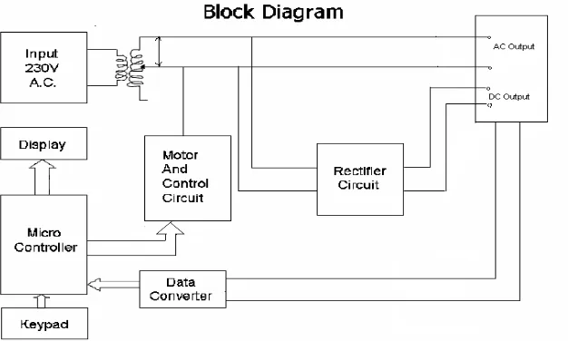
Fig 1 Block Diagram
Input section:
The input section consists of a keypad interfaced to the micro-controller. The keypad consists of number keys from 0 to 9 and clear and confirm keys.
Micro-controller:
The microcontroller used is an 89s51 chip. ADC 0808 is also integrated with the microcontroller and also is Connected to the Keypad. The pin number P0 and P1 of port 0 are connected to the motor control circuit. The LCD is interfaced with the port 0.The micro-controller is the heart of this system. It controls the various processes and makes the system efficient as well as hassle-free.
Rectifier Section:
The rectifier circuit is a full wave bridge rectifier. The diodes used in this system are IN Series diodes which can handle voltages up to250V. A capacitor is connected across the rectifier to filter the pulsating DC voltage obtained at the output.
Data Conversion Section:
Output Section:
A 16character 2line LCD is interfaced to the microcontroller. It shows the typed in voltage and the real time value of the voltage.
V. WORKING
The desired voltage is given as an input through the keypad. The controller accepts the input in binary format and stores it in the memory. This value is also displayed on LCD. The stored value is then compared with the reset value of the controller. After comparing the controller gives a command to the motor control circuit and accordingly the motor control circuit adjusts viper of the motor on the auto-transformer. A voltage is obtained at the output.
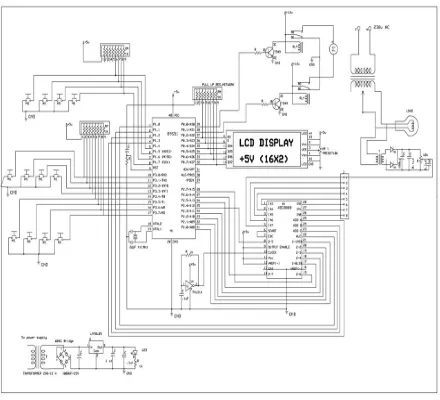
Fig 2 Circuit Diagram
VI.APLLICATIONS AND FUTURE SCOPE
A. Applications:
The project was designed basically for testing electrical devices having various ratings. The testing of the electrical devices was conventionally done with the help of a manually adjusted power supply. This project enables one to test electrical devices having voltage rating higher than the input voltage up to 260 volts in a short time. When testing a batch of such devices, a substantial amount of time is saved.
The system is not dependent on load, so besides the original purpose of designing it can be used for various other applications. In an electrical or electronic industry, this will act as a quick, easy and accurate power supply. With no manual adjustment or monitoring required, this system will be welcomed in any industry requiring a wide range of voltages for different purposes.
B. Future Scope:
The project is initially working on single phase supply but in future, according to the requirements, we can also use three phase supply as an input for which we have to incorporate two more PT arrangements.
The motor interfaced with a microprocessor can be used for various purposes such as solar tracking system, opening and closing of shutters or curtains, water level control by controlling valves, robotic appliances, etc. The error detecting circuit can be used for detecting sudden fluctuations or dangerous increase in line current.
The microprocessor may then provide proper signals for the atonement of these fluctuations or for cutting off the supply. The range of the output voltage can be varied by selecting the servo-motor mechanism with a suitable rating.
VII.RESULT AND CONCLUSION
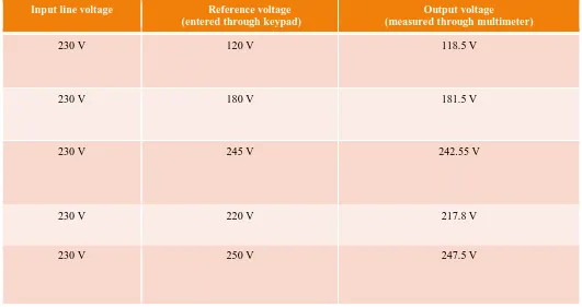
The design of the system is not complex and is easy to implement and understand. The voltage obtained at the output is nearly accurate but there still is 1% error because of the substandard equipment used in the piece of research.
Input line voltage Reference voltage
(entered through keypad)
Output voltage
(measured through multimeter)
230 V 120 V 118.5 V
230 V 180 V 181.5 V
230 V 245 V 242.55 V
230 V 220 V 217.8 V
230 V 250 V 247.5 V
Fig 4 Result Table
REFERENCES
[1] Patrick T. Murphy, Evolution Motor Control Design, Design News, Vol. 64, Issue 7, Jul 1, 2009, p. 14
[2] S. A. Prasad, B. S. Kariyappa, R. Nagary, S. K. Thakur, Microcontroller Based AC Power Controller, Wireless Sensor Network, Vol. 1, Issue 2, Jul 2009, pp. 76-81.
[3] SubrataChattopadhyay, UtpalChakrnborly, ArindanBhakta and Sagarika Pal, Microcontroller Based Closed Loop PMDC Motor Position Control System, Sensors & Transducers, Vol. 102, issue 3, March 2009, pp. 62-70.
[4] MarhaposanSitumorang ,The DC Motor Speed Controller Using AT89S52 Microcontroller to Rotate Stepper Motor Attached into Potentiometer in Variable Regulated Power Supply by, Published: 30 June 2011.