236 | P a g e
A SIMULATION COMPARISONS AND
IMPLEMENTATION OF INDUCTION
GENERATOR IN WIND POWER SYSTEMS
Muhammed Shahid
1, Ahmer Mahmood
21
Assistant Prof.,Department of Electrical & Electronics Engineering, Al-falah University, (India)
2
Student,M.Tech, Department of Electrical & Electronics Engineering, Al-falah University, India)
ABSTRACT
This paper describes the performance comparison of a wind power systems based on two different induction generators as well as the experimental demonstration of a wind turbine simulator for the maximum power extraction. The two induction machines studied for the comparison are the squirrel-cage induction generator (SCIG) and the doubly fed induction generator (DFIG). The techniques of direct grid integration, independent power control, and the droop phenomenon of distribution line are studied and compared between the SCIG and DFIG systems. With a competitive cost for electricity generation, wind energy conversion system (WECS) is nowadays deployed for meeting both grid-connected and stand-alone load demands. However, wind flow by nature is intermittent. In order to ensure continuous supply of power suitable storage technology is used as backup. The sustainability of a 4-kW hybrid of wind and battery system is investigated for meeting the requirements of a 3-kW stand-alone dc load representing a base telecom station. A charge controller for battery bank based on turbine maximum power point tracking and battery state of charge is developed to ensure controlled charging and discharging of battery. The mechanical safety of the WECS is assured by means of pitch control technique.Both systems are modeled in Mat lab/Simulink environment, and the operation is tested for the wind turbine maximum power extraction algorithm results. Based on the simulated wind turbine parameters, a commercial induction motor drive was programmed to emulate the wind turbine and is coupled to the experimental generator systems. The turbine experimental results matched well with the theoretical turbine operation.
237 | P a g e
I INTRODUCTION
This known to all that the burning of fossil fuels are having a vital influence on the global climatic conditions.
Effective changes in the climatic condition will require deep reduction in the emission of greenhouse gases. The
electricity systems are viewed as easier to transfer to low carbon energy source than most of the challenging sectors
of an economy such as surface and air transport. Hence the significant use of cost-effective and reliable low carbon
electricity generation sources, in addition to demand-side measures are becoming the most important objective of
energy policies in many countries. Over the past decades, wind energy has been accounted for the fastest rate of
growth among any form of electricity generation with its development stimulated by concerns over the climatic
changes, energy diversities and security of supply by many policy makers. The maximum energy that can be taken
out from the 0-100 meters layer of the atmosphere has been approximated to be around 10-12 kWh per year, which
is having the same potential as hydro-electric generation With a shortage of fossil fuels and global concerns for
environmental sustainability, the demand for renewable energy is increasing steadily. Wind energy conversion
system (WECS) is generally connected to the electric power grid and supplies electric power to supplement the base
power from other generation systems using fossil fuel or nuclear energy. The increasing emphasis on renewable
wind energy has given rise to augmented attention on more reliable and advantageous electrical generator systems.
Induction generator systems have been widely used and studied in wind power system because of their advantages
over synchronous generators, such as smaller size, lower cost, and lower requirement of maintenance. The
straightforward power conversion technique using squirrel cage induction generator (SCIG) is widely accepted in
fixed-speed applications with less emphasis on the high efficiency and control of power flow. The other major
problem with SCIG power system is the source of reactive power; that is, an external reactive power compensator is
required to hold the distribution line voltage and prevent the whole system from overload. On the other hand, the
doubly fed induction generator (DFIG) with variable-speed ability has higher energy capture efficiency and
improved power quality and thus has attracted more attentions. and a dc link, acts as an optimal operation tracking
interface between generator and grid. Although high robustness, reliability, and low maintenance cost are the
advantages of this system, it is a demerit that both the machine speed and the generated power are not controllable
but simply determined by the wind speed.
II THEORETICAL BACKGROUND
2.1 Singly Fed Induction Generator
The most common generator used in wind turbines is the induction generator. It has several advantages, such as
robustness and mechanical simplicity and, as it is produced in large series, it also has a low price. The major
disadvantage is that the stator needs a reactive magnetizing current. The asynchronous generator does not contain
permanent magnets and is not separately excited. Therefore, it has to receive its exciting current from another source
238 | P a g e
generator‘s magnetic field is established only if it is connected to the grid. In the case of AC excitation, the created
magnetic field rotates at a speed determined jointly by the number of poles in the winding and the frequency of the
current, the synchronous speed. Thus, if the rotor rotates at a speed that exceeds the synchronous speed, an electric
field is induced between the rotor and the rotating stator field by a relative motion (slip), which causes a current in
the rotor windings. The interaction of the associated magnetic field of the rotor with the stator field results in the
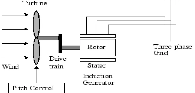
torque acting on the rotor. So far, the Squirrel Cage Induction Generator (SCIG) has been the prevalent choice
because of its mechanical simplicity, high efficiency and low maintenance requirements. The SCIG is directly
coupled to grid. Hence this is normally used in Fixed Speed configuration as the generator frequency and grid
frequency should match for synchronism.
Fig 2.1 Squirrel cage Induction Generator connected to the grid on the stator
and wind turbine on the rotor
2.2 Doubly Fed Induction Generator
The Doubly Fed Induction Generator (DFIG) comes under the category of Wound Rotor Induction Generators
(WRIG). In the case of a WRIG, the electrical characteristics of the rotor can be controlled from the outside, and
thereby a rotor voltage can be impressed. The windings of the wound rotor can be externally connected through slip
rings and brushes or by means of power electronic equipment, which may or may not require slip rings and brushes.
By using power electronics, the power can be extracted or impressed to the rotor circuit and the generator can be
magnetized from either the stator circuit or the rotor circuit. It is thus also possible to recover slip energy from the
rotor circuit and feed it into the output of the stator. The disadvantage of the WRIG is that it is more expensive than
the SCIG and not as robust as the SCIG.The DFIG consists of a WRIG with the stator windings directly connected
to the constant-frequency three-phase grid and with the rotor windings mounted to a bidirectional back-to-back
IGBT voltage source converter. The term ‗doubly fed‘ refers to the fact that the voltage on the stator is applied from
the grid and the voltage on the rotor is induced by the power converter. This system allows a variable-speed
operation over a large, but restricted, range. The converter compensates the difference between the mechanical and
239 | P a g e
the behavior of the generator is thus governed by the power converter and its controllers. The power converter
consists of two converters, the rotor-side converter and grid-side converter, which are controlled independently of
each other.
Fig.2.2 Rotor of the DFIG connected through the power electronics to the grid and the stator is connected
directly to the grid
III INDUCTION GENERATOR
3.1 SCIG Wind Power System
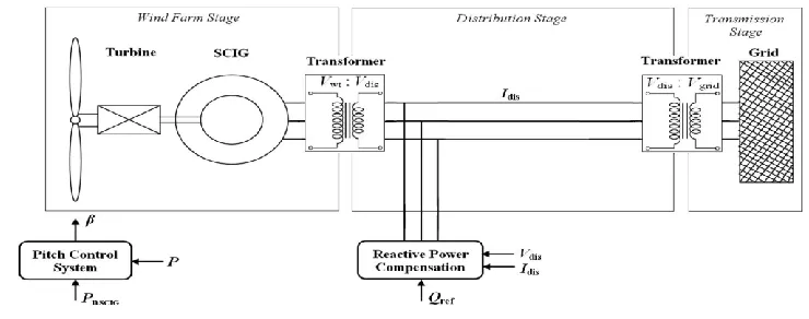
The schematics of the SCIG system including the wind turbine, pitch control, and reactive power compensator. The
entire system includes three stages for delivering the energy from wind turbine to the power grid. The first one is
wind farm stage which handles with low voltage Vwt, the second is distribution stage which has medium voltage
Vdis, and the third is grid transmission stage which has high voltage Vgrid. The three-phase transformers take care
of the interface between stages [9]. As mentioned, nominal power PnSCIG is considered as active power reference
to regulate the pitch angle while Vdis and Idis denote the distribution line-to-line voltage and phase current, and they
are monitored to favor the reactive power compensation for distribution line.
240 | P a g e
This fairly straightforward technique was first used since it is simple and has rugged construction, reliable operation,
and low cost. However, the fixed-speed essential and potential voltage instability problems severely limit the
operations of wind turbine [1], [5]. Since SCIG is of fixed-speed generator, for a particular wind speed, the output
active power is fixed as well. Thus, with the increase of wind speed, so does the output power until the nominal
power is reached.
Pitch angle control is called nominal wind speed. Beyond this speed, the pitch angle system will prevent the output
power from exceeding the nominal value. That is, when the wind speed is below nominalvalue, the power capture
can vary with the change of wind speed; and when the wind speed is above nominal value, the pitch angle control
system will limit the generated power by changing the pitch angle. In such way, the output power will be stabilized
at nominal value where the wind speed is always above nominal speed.. Due to the huge size of blade and, thus,
inertia, pitch angle has to change in a slow rate and a reasonable range. It is also worthy to notice that, without
reactive power source, in Section V, the SCIG system tends to lead to a voltage droop in distribution line which will
cause overload problem.
3.2. DFIG Wind Power System
Traditionally, the dynamic slip control is employed to fulfill the variable-speed operation in wind turbine system, in
which the rotor windings are connected to variable resistor and control the slip by the varied resistance [5], [10].
This type of system can achieve limited variations of generator speed, but external reactive power source is still
necessary. Consequently, to completely remove the reactive power compensation and to control both active and
reactive power independently, DFIG wind power system is one of most popular methods in wind energy
applications [1], [5], [7]. This paper reproduces DFIG model first of all and then concentrates on the controlling
schemes of power converters, in which the active and reactive power are controlled independently. In particular, the
stator-side converter control involving an RL series choke is proposed Both controlling of rotor- and stator-side
converter voltages end up with a current regulation part and a cross-coupling part. The wind turbine driving DFIG
wind power system consists of a wound-rotor induction generator and an ac/dc/ac insulated gate bipolar transistor
(IGBT)-based pulse width-modulated (PWM) converter (back-to-back converter with capacitor dc link), as shown in
Fig. 7. In this configuration, the back-to-back converter consists of two parts: the stator-/grid-side converter and the
rotor-side converter. Both are voltage source converters using IGBTs, while a capacitor between two converters acts
as a dc voltage source. The generator stator windings are connected directly to grid (with fixed voltage and
frequency of grid) while the rotor winding is fed by rotor-side converter through slip rings and brushes, at variable
frequency. The control system is divided into two parts—stator-side converter control system and rotor-side
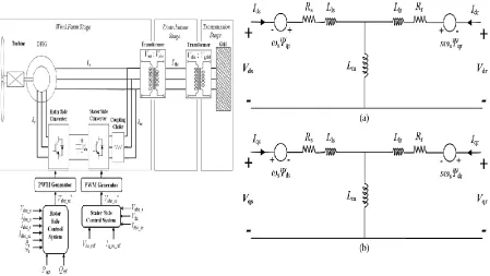
converter control system. An equivalent circuit of DFIG is depicted in Fig. 8, and the relation equations for voltage
241 | P a g e
where Ls= Lls+ Lm; Lr= Llr+ Lm; sωs= ωs− ωr represents the difference between synchronous speed and
rotorspeed; subscripts r, s, d, and q denote the rotor, stator, d-axis, and q-axis components, respectively; Te is
electromagnetic torque; and Lm, np, and J are generator mutual inductance, the number of pole pairs, and the inertia
coefficient, respectively.
Fig. 3.2 Wind turbine–doubly fed induction Fig. 3.3 Equivalent circuit of DFIG.
242 | P a g e
IV SIMULATION MODEL DEVELOPMENT
4.1 SCIG Model in MATLAB
In MATLAB, the SCIG is represented using a phasor model. This model is adapted to simulate the low frequency
electromechanical oscillations over long periods of time. In phasor simulation method, the sinusoidal voltages and
currents are replaced by phasor quantities at the system nominal frequency (50Hz). This model is mostly used for
transient stability studies of wind turbines. Shown in Fig.4.1 is the model of the SCIG used in MATLAB.
Fig.4.1 Model of the SCIG in MATLAB Simulink Fig.4.2 Model of the DFIG in MATLAB Simulink
4.2 Doubly Fed Induction Generator Model in MATLAB
In MATLAB, the DFIG is represented using a phasor model. This model is adapted to simulate the low frequency
electromechanical oscillations over long periods of time. In phasor simulation method, the sinusoidal voltages and
currents are replaced by phasor quantities at the system nominal frequency (50Hz). This model is mostly used for
transient stability studies of wind turbines. Shown in Fig.4.2 is the model of the Double Fed Induction Generator
used in MATLAB.
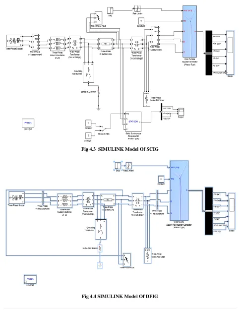
4.3 Topology of Wind Turbines for Comparison of Wind Turbine
The wind turbines are connected to produce 1.5 MW of real power excluding losses. The above mentioned models
243 | P a g e
Fig 4.3 SIMULINK Model Of SCIG244 | P a g e
V SIMULATION RESULT
5.1 PARAMETERS OF DFIG& SCIG
Parameter Value
Nominal Power(MW) 1.5
Nominal Voltage(V) 575
Nominal Power Factor 0.9
Stator Resistance(pu) 0.004843
Stator Leakage Inductance(pu) 0.1248
Rotor Resistance(pu) 0.004377
Rotor Leakage Inductance(pu) 0.1791
Magnetizing Inductance(pu) 6.77
Inertia Constant 5.04
Friction Factor 0.01
Pole Pairs 3
Table : 1 Parameters Of DFIG Table : 2 Parameters Of SCIG
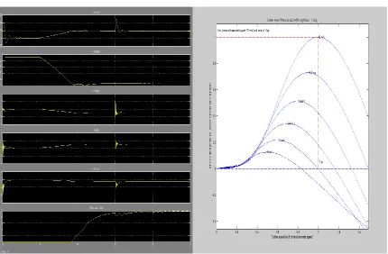
Fig 5.1 Simulation Result Of SCIG Fig 5.2 Wind Tubine Power CharcterisitcsOf SCIG
Parameter Value
Nominal Power(MW) 1.5
Nominal Voltage(V) 575
Nominal Power Factor 0.9
Stator Resistance(pu) 0.00706
Stator Leakage Inductance(pu) 0.171
Rotor Resistance(pu) 0.005
Rotor Leakage Inductance(pu) 0.156
Magnetizing Inductance(pu) 2.9
Inertia Constant 5.04
Friction Factor 0.01
245 | P a g e
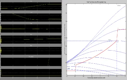
Fig 5.3 Simulation Result Of DFIG
Fig 5.4 Wind Tubine Power Characteristics of DFIG
VI CONCLUSION
This paper has presented the comparison of the wind turbinesystems using SCIG and DFIG generator systems. With
theexperimentally investigated wind turbine model, a SCIG anda DFIG wind power systems are modeled and
simulated inMatlab/Simulink. An optimal active-power-versus-rotor-speed relationship has been proposed for
turbine model first, and it functions as a lookup table for tracking the maximum output active power. The SCIG
system presents the need of external reactive power source to support grid voltage, and it can keep the output power
at the nominal level by pitch control but cannot accordingly change the rotor speed to achieve maximum wind
power capture at different wind speeds. In contrast, the DFIG system does not need reactive power compensator to
hold distribution line voltage and achieves optimal active power controlling. Both voltage control schemes for two
converters consist of a current regulation part and a cross-coupling part. The turbine emulator system performs well
246 | P a g e
REFERENCES
[1] M. Orabi, T. Ahmed, and M. Nakaoka, ―Efficient performances of inductiongenerator for wind energy utilization,‖ in Proc. 30th Annu.Conf.IEEE Ind. Elect. Soc., Nov. 2004, pp. 838–843.
[2] M. Molinas, J. A. Suul, and T. Undeland, ―Low voltage ride through ofwind farms with cage generators: STATCOM versus SVC,‖ IEEE Trans.Power Electron., vol. 23, no. 3, pp. 1104–1117, May 2008.
[3] Z. Chen, J. M. Guerrero, and F. Blaabjerg, ―A review of the state of thEart of power electronics for wind
turbines,‖ IEEE Trans. Power Electron.,vol. 24, no. 8, pp. 1859–1875, Aug. 2009.
[4] Y. Lei, A. Mullane, and G. Lightbody, ―Modeling of the wind turbine witha doubly fed induction generator for
grid integration studies,‖ IEEE Trans.Energy Convers., vol. 21, no. 1, pp. 257–264, Mar. 2006.
[5] R. Ganon, G. Sybille, and S. Bernard, ―Modeling and real-time simulationof a doubly-fed induction generator driven by a wind turbine,‖ presentedat the Int. Conf. Power Systems Transients,Montreal, QC, Canada,
Jun. 2005, Paper IPST05-162.
[6] H. Sun, Y. Ren, and H. Li, ―DFIG wind power generation based on backto-back PWM converter,‖ in Proc. IEEE
Int. Conf. Mechatron. Autom.,Aug. 2009, pp. 2276–2280.
[7] L. Xu and P. Cartwright, ―Direct active and reactive power control ofDFIG for wind energy generation,‖ IEEE
Trans. Energy Convers., vol. 21,no. 3, pp. 750–758, Sep. 2006.
[8] S. Heier, Grid Integration of Wind Energy Conversion Systems.Hoboken, NJ, USA: Wiley, 2006.
[9] N. W. Miller, W. W. Price, and J. J. Sanchez-Gasca, ―Dynamic modelingof GE 1.5 And 3.6 wind
turbine-generators,‖ GE Power Systems EnergyConsulting, Gen. Elect. Int., Inc., Schenectady, NY, USA, Oct. 2003.
[10] R. Pena, J. C. Clare, and G. M. Asher, ―Doubly fed induction generatorusing back-to-back PWM converters
and its application to variable-speedwind-energy generation,‖ Proc. Inst. Elect. Eng.—Elect. Power Appl.,
vol. 143, no. 3, pp. 231–241, May 1996.
[11] Feijoo, J. Cidras, and C. Carrillo, ―Third order model for the doubly-fedinduction machine,‖ Elect. Power Syst.