Scholarship@Western
Scholarship@Western
Electronic Thesis and Dissertation Repository
9-18-2014 12:00 AM
A Multiple Bit Parity Fault Detection Scheme for The Advanced
A Multiple Bit Parity Fault Detection Scheme for The Advanced
Encryption Standard Galois/Counter Mode
Encryption Standard Galois/Counter Mode
Amir Hossein Ali Kouzeh Geran
The University of Western Ontario
Supervisor
Dr. Arash Reyhani Masoleh The University of Western Ontario
Graduate Program in Electrical and Computer Engineering
A thesis submitted in partial fulfillment of the requirements for the degree in Master of Engineering Science
© Amir Hossein Ali Kouzeh Geran 2014
Follow this and additional works at: https://ir.lib.uwo.ca/etd Part of the Electrical and Electronics Commons
Recommended Citation Recommended Citation
Ali Kouzeh Geran, Amir Hossein, "A Multiple Bit Parity Fault Detection Scheme for The Advanced
Encryption Standard Galois/Counter Mode" (2014). Electronic Thesis and Dissertation Repository. 2498. https://ir.lib.uwo.ca/etd/2498
This Dissertation/Thesis is brought to you for free and open access by Scholarship@Western. It has been accepted for inclusion in Electronic Thesis and Dissertation Repository by an authorized administrator of
A MULTIPLE BIT PARITY FAULT DETECTION SCHEME FOR THE
ADVANCED ENCRYPTION STANDARD GALOIS/COUNTER MODE
by
Amir Hossein Ali Kouzeh Geran
Graduate Program in Electrical and Computer Engineering
A thesis submitted in partial fulfillment of the requirements for the degree of
Masters of Science
The School of Graduate and Postdoctoral Studies The University of Western Ontario
London, Ontario, Canada
c
The Advanced Encryption Standard (AES) is a symmetric-key block cipher
for electronic data announced by the U.S. National Institute of Standards and
Technology (NIS T) in 2001. The encryption process is based on symmetric key (using the same key for both encryption and decryption) for block
encryp-tion of 128, 192, and 256 bits in size. AES and its standardized authenticaencryp-tion
Galois/Counter Mode (GCM) have been adopted in numerous security-based applications. GCM is a mode of operation for AES symmetric key
crypto-graphic block ciphers, which has been selected for its high throughput rates in
high speed communication channels.
The GCM is an algorithm for authenticated encryption to provide both data
authenticity and confidentiality that can be achieved with reasonable hardware
resources. The hardware implementation of the AES-GCM demands
tremen-dous amount of logic blocks and gates. Due to natural faults or intrusion
at-tacks, faulty outputs in different logic blocks of the AES-GCM module results in erroneous output. There exist plenty of specific literature on methods of fault
detection in the AES section of the AES-GCM.
In this thesis, we consider a novel fault detection of the GCM section using
parity prediction. For the purpose of fault detection in GCM, two independent
methods are proposed. First, a new technique of fault detection using parity
prediction for the entire GCM loop is presented. Then, matrix based CRC
multiple-bit parity prediction schemes are developed and implemented. As a
result, we achieve the fault coverage of about 99% with the longest path delay
and area overhead of 23% and 10.9% respectively. The false alarm is 0.12%
which can be ignored based on the number of injected faults.
Keywords: Fault Detection, Parity Prediction, AES-GCM, Matrix Based CRC
I would like to express my sincere appreciation to Prof. Arash
Reyhani-Masoleh for his extra care, great supervision and guidance during my studies
and preparation of this thesis.
Amir Ali Kouzeh Geran
London, ON
2014
Contents
Abstract ii
Acknowlegements iv
List of Figures viii
List of Tables ix
List of Appendices x
1 Thesis Contributions and Outline 1
1.1 Introduction . . . 1
1.1.1 Advanced Encryption Standard(AES) . . . 1
1.1.2 Galois/counter Mode(GCM) . . . 1
1.2 Motivation and Scope of Thesis . . . 2
1.3 Contributions . . . 4
1.4 Thesis Outline . . . 5
2 Priliminaries and Literature Review 7 2.1 Finite Field . . . 7
2.1.1 Principles of Galois Field . . . 8
2.1.2 Finite Field Arithmetic . . . 8
2.1.3 ExampleGF(23) . . . 10
2.2 The GCM Operation . . . 11
Encryption Process . . . 13
2.2.2 The GCM Block Diagram . . . 15
2.2.3 Review on GHASH . . . 16
Software Implementation of High Performance GHASH Algorithms . . 16
High Performance GHASH Function for Long Messages . . . 16
An Architecture for the AES-GCM Security Standard . . . 17
2.3 The AES Operation . . . 17
2.3.1 Fault Attacks and Detection in AES . . . 19
Fault Attacks . . . 19
Fault Detection . . . 20
2.4 Finite Field Multipliers In AES-GCM . . . 22
2.4.1 Low Complexity Multiplier inGF(2m) . . . 23
2.5 Fault Detection In Multiplier . . . 27
3 Single bit fault detection in GCM 31 3.1 Fault Detection Scheme . . . 31
3.1.1 Parity for the powers of the Hash Key(H) . . . 33
3.1.2 Parity Prediction for the Multiplier in the GCM . . . 35
3.1.3 Fault Detection in the GCM Loop . . . 36
4 Multiple Parity Bit Fault Detection Architecture 39 4.1 Introduction . . . 39
4.2 Matrix-Based Parity Prediction Scheme in GCM Loop . . . 40
4.2.1 Matrix-Based Single Parity Bit Scheme . . . 40
4.2.2 Matrix-Based Random Parity Bit Scheme . . . 42
4.3 Matrix-based CRC for Multi-Bit Parity Fault Detection . . . 44
4.3.1 Brief review on CRC . . . 44
4.3.2 Matrix-Based Double Bit Parity CRC . . . 45
4.3.3 Matrix-Based Double Bit Parity Prediction CRC . . . 48
4.3.4 Matrix-basedkBit Parity Fault Detection (k >2) . . . 50
4.3.5 Fault Detection Architecture . . . 51
5 Testing and Simulation 54 5.1 Introduction . . . 54
5.2 VHDL Implementation of Fault Model . . . 55
5.3 Fault Injection in the GCM loop . . . 58
5.4 Simulation Results . . . 58
5.5 Fault Detection Overhead and Delay Analysis . . . 61
5.6 Future Work . . . 63
Bibliography 71
A VHDL Implementation 74
B Fault Injection TLC 86
2.1 Block Diagram of AES-GCM . . . 18
2.2 Block Diagram of Multipliers a. Parallel b. Bit-level c. Digit-level . . . 23
2.3 Demonstration ofL,U, andbin Matrix Presentation.. . . 24
2.4 Demonstration ofQin matrix presentation . . . 27
2.5 QT demonstration 128×127 . . . 28
3.1 Parity prediction scheme . . . 36
3.2 AES-GCM loop parity prediction scheme . . . 38
3.3 Output error indicator . . . 38
4.1 Implementation of Matrix(Register)oE . . . 43
4.2 Block Diagram of Double Bit Parity. . . 44
4.3 Hardware implementation of Double Bit Parity Generator on multiplier output. . . 48
4.4 Error signal generator. . . 50
4.5 Block diagram ofk−bit parity fault detection in GCM loop. . . 53
5.1 Demonstation of MatrixQTU. . . . 65
5.2 The flow chart of fault injection. . . 66
5.3 Gate level fault injection for matrix elementQTU(1,123) . . . 67
5.4 The GCM loop and related components . . . 67
5.5 The simulation results. . . 68
5.6 The simulation results graph: (a) fault coverage, (b) critical path delay, (c) area over-head, and (d) false alarm versus the number of parity bits. . . 69
List of Tables
2.1 αisinGF(8) based onx3+x2+1. . . . 11
4.1 Irreducible Polynomials to the degree 5. . . 51
4.2 pCRCMatrix pattern for selected polynomials. . . 51
5.1 Fault coverage in the GCM loop versus selected parity bits. . . 61
5.2 Area overhead and delay versus selected parity bits. . . 61
5.3 Gate level area overhead and delay versus selected parity bits, whereTX,TA, andTO are the propagation delays of XOR, AND, and OR Gate respectively. . . 62
5.4 False Alarm in the GCM loop versus selected parity bits. . . 63
Appendix A VHDL Implementation . . . 74
Appendix B Fault Injection TLC . . . 86
Chapter 1
Thesis Contributions and Outline
1.1
Introduction
1.1.1 Advanced Encryption Standard(AES)
The Advanced Encryption Standard (AES) has been widely used in
cryptosys-tems after it was introduced by NIS T [14] in 2001. It was a replacement for Data Encryption Standard (DES) [6]. Since then, many different hardware and software projects have been developed and implemented to obtain more effi -cient area and timing results.
1.1.2 Galois/counter Mode(GCM)
The Galois Counter Mode of operation (GCM) [1] is a combined encryption
and authentication process introduced by David Mcgrew and John Viega [22].
The mode is defined in NIST SP 800-38D [35]. The GCM is a mode of
op-eration that uses a universal hash function over a binary Galois field to
pro-vide assurance of the authenticity and the confidentiality of data in its
encryp-tion/decryption. The GCM can also provide authentication assurance for
tional data that is not encrypted. In particular, GCM can detect both accidental
modifications of the data, or unauthorized alterations to ensure proper
authen-tication while protects confidentiality to make the data readable by intended
receiver. It could be implemented into the hardware to achieve high speed
op-eration with low cost and low latency.
The AES-GCM has been widely used in networking communications. In
general, fault detection techniques can be very useful towards the protection of
encryption and malicious attack prevention. The GCM is designed to support
very high data rates due to pipelining and parallel processing techniques as well
as high degree of authenticity and confidentiality. This will result in
authenti-cated encryption at data rates of many tens of Gbps, permitting high grade encryption and authentication on communication systems. Recently, the GCM
is being used in lower data rate applications. Therefore, much more reliable
fault detection techniques are needed in industry level.
1.2
Motivation and Scope of Thesis
There are two sources of faults in cryptography systems, natural faults and fault
attacks. The natural faults are caused by physical defects in the ASIC or the
electrical circuit malfunction. Four common types of defects occur in logic
gates during the fabrication or due to physical failure i.e., the bridging or short
1.2. Motivation andScope ofThesis 3
logic 0 or logic 1 which is modeled by stuck-at-0 and stuck-at-1 respectively
(in general stuck-at-fault). The stuck-at-fault model assumes that only one
in-put or outin-put on each gate will be faulty at a time. Assuming that if more than
one are faulty, a test that can detect any single fault, should easily find multiple
faults.
The intruder attack consists of a series of fault injection into the system to
ob-tain any leakage of secret information, this type of transient fault should also be
detected to prevent such attacks. Therefore, the need for a robust fault detection
method is highly demanded to have much more protection for the integrity and
authenticity of data over the communication channels. As soon as the attacker
inject the fault into the system, the fault detection module generates an error
signal to prevent the system to proceed to the next level. Thus, the attacker
won’t be able to complete the attack sequence. This thesis aims to create a
reliable GCM module which is capable of detecting permanent and transient
faults. To make a system more reliable against faults, there have been three
dif-ferent approaches towards the fault detection [5]. These methods are hardware,
time, and information redundancy. In hardware redundancy technique, one can
duplicate hardware to the system for fault detection which causes 100% fault
detection versus 100% area overhead. In time redundancy approach, the
func-tion of hardware is evaluated in different time slices to detect transient faults. Again, one can obtain 100 percent fault coverage versus 100% delay increase.
parity bits to the system to locate the faults.
The goal of this thesis is to introduce a novel method of fault detection in
the GCM module using the information redundancy technique by adding parity
bits to the Circuit Under Test (CUT).
1.3
Contributions
In this thesis, we have introduced a novel matrix based CRC fault detection
ar-chitecture using multiple bit parity prediction method for entire the GCM loop
with high rate of fault coverage which is about 99%. The proposed scheme is
generic and the number of parity bits can be adjusted based on the available
re-sources and needed fault coverage. The proposed fault detection schemes can
be applied as an universal method of fault detection because of its unique
pro-cessing of CRC pattern generation. The proposed fault injection using VHDL
and Tcl programming makes the design verification and testing easier, faster,
and more reliable. The contributions of the thesis are summarized as follows:
• A new fault detection scheme for the entire GCM module using the GCM
charactristics defined by NIST [35] and Galois field principles including
the formulations and block diagram.
• New approach in using CRC method to generate fault detection patterns
based on the number of the used parity bits. All formulation, CRC patterns
1.4. ThesisOutline 5
• A new method of fault injection in the GCM module using the VHDL is
proposed. Both the GCM and fault injection are implemented in VHDL.
• Tcl stimulus script is used to activate the fault injection for simulation of
proposed fault detection to investigate the fault coverage.
• Implementation of the fault detection scheme is performed on FPGA for
area overhead and timing analysis. This thesis outlines an accurate and
reliable GCM module which detects all types of faults in each clock cycle
to prevent sending false information through the communication channels.
1.4
Thesis Outline
We have developed a formal model in hardware that allows us to formulate the
fault detection problem for arbitrary permanent and transient faults in the entire
GCM loop. In Chapter 2, we explain the Authenticated encryption/decryption in GCM, inputs and outputs of GCM, and the GCM block diagram. We also
outline the principles of Galois field and previous work has been done on AES
and multipliers fault detection. In Chapter 3, we have introduced a novel parity
prediction scheme for entire GCM module using the properties of GCM and
ap-plication of Galois field principles. In Chapter 4, we have established a reliable
matrix based CRC (Cyclic Redundancy Check) multi- bit parity prediction.
The proposed scheme is generic in terms of the number of used parity bits. If
in detecting permanent and transient faults. Chapter 5 depicts the simulation
results and implementation in FPGA as well as timing and overhead analysis.
A new method of fault injection in the GCM module using VHDL language
Chapter 2
Priliminaries and Literature Review
In this chapter, we have an overview on the Galois field principles, GCM
char-acteristics and operation, AES operation and related fault detection, and the
multiplier module used in GCM block. The bit-parallel multiplier and the fault
detection in the multiplier module will be discussed. The multiplier consists
of tremendous amount of gates which could generate the faulty output due to
natural or transient faults in any part of its structure. The area overhead of the
multiplier in the GCM is up to 30% of the total space [38]. Therefore, the
se-lection of low complexity multiplier contributes towards the final cost and the
operating frequency.
2.1
Finite Field
Finite field arithmetic [20], [19] has become prominent solution in different ap-plications like cryptography and digital communication systems. In the GCM
implementation, each ciphertext is treated as an element of a finite field. During
the Tag generation process, each ciphertext or element of the field is multiplied
by Hash Key H, or added to another field element. The element H is consid-ered constant field element which does not change until the next encryption.
2.1.1 Principles of Galois Field
Only binary field is used in the GCM. Therefore, we explain the Galois Field
GF(2m) which is extensively employed in the GCM implementation. Thus, we mainly focus on binary extension fields in thesis. The number of elements
in the field is equal to 2m. The elements of the field are represented by
poly-nomials with coefficients belonging to GF(2). The elements of the field are generated by selecting irreducible polynomial F(x) which cannot be factored into any polynomials in GF(2m) [23]. All the elements in GF(2m) are repre-sented by polynomials modulo F(x). The multiplication is done modulo the selected irreducible polynomial.
2.1.2 Finite Field Arithmetic
Addition In Galois Field
Let A and B represent two elements in GF(2m). Then, one can write each element according to its polynomial representation:
A= m−1
X
i=0
aixi =am−1xm−1+· · ·+a0
B= m−1
X
i=0 bix
i = bm−1x
m−1+· · ·+
b0
ai ∈ {0, 1}
bi ∈ {0, 1}
2.1. FiniteField 9
The addition is componentwise sum of each element inGF(2m) overGF(2) which can be written as follows
A+ B=
m−1
X
i=0
(ai+bi)xi (2.2)
Therefore, addition is performed by bitwise exclusive-or (XOR) of the ele-ments of the field. Thus, we represent all addition with +sign hereafter which denotes XORoperation on coordinates of field elements.
Multiplication In Galois Field
The result of multiplication of A and B defined in (2.1) and denoted by S is a polynomial with order of 2m−2 shown as
S = AB = s2m−2x2m−2 +· · ·+s1x1 + s0 (2.3)
It is reduced to the order of m− 1 after modular reduction, if x is the root of irreducible polynomial generating the field elements, then the final result of
multiplication depends solely on the chosen irreducible polynomial.
C = AB mod F(x) ∈GF(2m)
C = cm−1xm−1 +· · ·+c0
(2.4)
For the purpose of this thesis, we use the recommended irreducible polynomial
f(x) = x128 +x7 +x2 +x+1 (2.5)
2.1.3 ExampleGF(23)
In order to clarify the concept of irreducible polynomial and the polynomial
basis, an example is given in GF(23) for simplicity. One can extend the con-cept toGF(2128) which is discussed in the following Chapters.
To define the field structure and elements, we need to define the monic
irre-ducible polynomial f(x) in GF(23) over GF(2). The irreducible polynomial
f(x) is shown in [19] as
f(x) = x3 +
2
X
i=0
fixi fi ∈ {0, 1} (2.6)
It is clear that f0 must be 1, otherwise f(x) is not irreducible and could be divided by x.The sum of coefficients must be 1, otherwise x+1 will be a factor and f(x) becomes reducible. Thus, 1+ f2+ f1+1 must be 1.Therefore, f1 or f2 must be 0.As result, we outline the following monic polynomials in GF(23).
x3 +x2 +1 and x3 + x+1 (2.7)
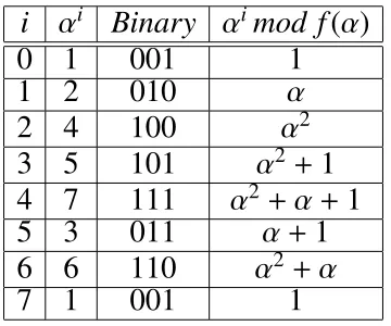
Either polynomials can be used to define the the elements of the field. If α
2.2. TheGCM Operation 11
calculate αisshown in Table 2.1.
i αi Binary αimod f(α)
0 1 001 1
1 2 010 α
2 4 100 α2
3 5 101 α2 +1
4 7 111 α2 +α+1
5 3 011 α+1
6 6 110 α2 +α
7 1 001 1
Table 2.1: αisinGF(8) based onx3+x2+1.
We can easily show that every nonzero element of GF(23) is a power of
α and also the linear combination of the polynomial basis {1, α, α2}. Here, α
is called primitive element. The selection of irreducible polynomial leads to
the maximum number of distinguished elements in the related field. Therefore,
one can process eight different field elements out of 3 bit length in the above example ofGF(23).
As an example multiplication of two field elements 010 and 100 is α3 which
results another field element 101.
2.2
The GCM Operation
The GCM performs authentication and encryption of data at high speeds for
both software and hardware implementations. Data integrity is achieved by
ci-pher named Advanced Encryption Standard (AES) is used for the purpose of confidentiality. The GCM uses block cipher for authenticity. A block
ci-pher is a symmetric key cici-pher operating on fixed-length groups of bits, called
blocks [27]. The mode of operation defines how to repeatedly apply a cipher’s
block operation to transform amounts of whole plaintext which has been
di-vided into fix-sized blocks. The GCM requires a unique IV for each encryp-tion operaencryp-tion. The IV must be random and should not repeat for other encryp-tion. This leads to generation of different ciphertexts even the same plaintext is encrypted multiple times with the same key. The security of AES-GCM
de-pends on the freshness of the nonce/key combination. Thus, we cannot use statically configured keys. Instead, an automated key management system is
implemented. Authors in [4] have discussed four general key management
techniques i.e., Key Transport, Key Agreement, Key-Encryption Keys, and
Passwords. The GCM could be implemented in pipeline form, which results
in throughput of more than 10Gbps. While in Tag generation process of the GCM, a chained Galois multiplication is used, the sequential data (Ciphertext) can be fed in through the pipeline form.
2.2.1 Encryption/Decryption in GCM
2.2. TheGCM Operation 13
number between 1 and 264 that is unique for each application. A plaintext P, that can have any number of bits between 0 and 239 −256. Additional
authen-ticated data (AAD) denoted by A which is authenticated by the GCM module, but not encrypted. AAD includes version numbers, port, address or other field information can be a number between 0 and 264. There are two outputs: A
ciphertextC with the same length as the plain textP. An authentication tag T, whose length can be any value between 0 and 128.
The authenticated decryption operation has five inputs: K, IV,C, A, andT. It either generates the plaintext P, or a FAIL signal once the inputs are not authentic for the shared key.
Encryption Process
The plaintext P is divided into the blocks of 128 bit long. Let n and u be two positive integers, then the total number of bits inPcan be written as (n−1)128+
u where 1 ≤ u ≤ 128. As a result, P can be shown as P1, P2, . . . , Pn−1, P∗n,
which are called data blocks with the length of 128 bits except for the last block
that could be less than 128 bits.
Similarly, the ciphertext C is represented as C1, C2, . . . , Cn−1, C∗n. The
additional authenticated data A is also represented as A1, A2, . . . , Am−1, A∗m.
The total number of bits required for Acan be written as (m−1)128+v,mand
vare two positive integers where 1 ≤v ≤128.
defined by Xm+n+1 =GHAS H(H,A,C) as
Xi =
0 f or i = 0
(Xi−1 ⊕Ai)· H f or i = 1, . . . ,m−1
(Xm−1 ⊕(A?m k0128−v))· H f or i = m
(Xi−1 ⊕Ci−m)· H f or i = m+1, . . . ,m+n−1
(Xm+n−1 ⊕(C?n k 0128
−u)) ·H f or i = m+n
(Xm+n ⊕(len(A)klen(C))·H f or i = m+n+1
(2.8)
Two operations are used in (2.8) denoted by “⊕” for XOR and “· ” for the finite field multiplication overGF(2128) which is explained in previous section. The len() function is used for generating the length block, its function is to compute the total number of bits in the operand and returns a 64 bit value. AAD
and the ciphertext are applied to thelenfunction, then the result is concatenated to create the length block.
The sets of equation to define the authenticated encryption operation are
defined in [35] as follows
H = E(K,0128)
U0 =
IV k 0311 i f len(IV) = 96
GHAS H(H,{},IV) otherwise
Ui =incr(Ui−1) f or i = 1, . . . , n
Ci = Pi ⊕E(K,Ui) f or i = 1, . . . , n
T = MS Bt(GHAS H(H,A,C)⊕E(K,U0)
(2.9)
2.2. TheGCM Operation 15
block of all zero. the incr() function increments the value of the the counter
U by one in each clock cycle. This value will be XORed with E(K,U0) which is the AES encryption of shared key (K) and the initial counter value U0. At the final stage, the Authentication Tag T is generated by choosing the t most significant bits of the result. The initial value of the counter is U0 = (IV k 0311) if len(IV) = 96, otherwise GHAS H(H, {}, IV). The counter will be incremented by one at each clock cycle using the incr() function. Then, the AES encrypted value of the counter will be added to the plaintextPi to generate
the ciphertextCi which will be applied to theGHAS H calculator in (2.8).
2.2.2 The GCM Block Diagram
As stated in previous section, the main part of the GHAS H function in the GCM is multiplication of (Xi−1 ⊕ Ci) by H in GF(2128). Figure 2.1
illus-trates the block diagram for GCM. In this scheme, we consider sequential
structure for the multiplier and apply Ai or Ci and H in block-length of 128
in serial to GHAS H calculator in (2.8). In this figure, the 128-bit register
Y = (y127, ..., y2, y1, y0) will be initialized by all zeros at the beginning of
the clock cycle. Let Y(n) denote the contents of Y at the nth clock cycle. Let
Xi be the multiplier output at ith clock cycle. Furthermore, the initial value
of register X0=Y(0) =(0, . . . , 0). Thus, the content of Y after the first clock cycle shows as X1 = Y(1) = C1 · H, in the second clock cycle we obtain
in the (m+n+1)thclock cycle as defined in (2.8).
Ai or encrypted Pi can be selected through the multiplexer based on the values
ofmand n.
2.2.3 Review on GHASH
Software Implementation of High Performance GHASH Algorithms
Authors in [34] provide an efficient way of software implementation of high performance GHASH function and also on the implementation of GHASH
using a carry-less multiplication instruction supplied by Intel. The work
in-cludes implementation of the high performance GHASH and its comparison
to the standard implementation of GHASH function. It also includes
compar-ison of the two implementations using Intels carry-less multiplication
instruc-tion. The proposed software implementations suggest that the new GHASH
algorithm can’t take advantage of the Intel carry-less multiplication
instruc-tion PCLMULQDQ. The work shows that the implementainstruc-tions done without
using the PCLMULQDQ instruction performs better. This suggest that the
new algorithm will perform better on embedded systems that do not support
PCLMULQDQ.
High Performance GHASH Function for Long Messages
Authors in [27] present a new method to compute the GHASH function. AS
2.3. TheAES Operation 17
GF(2128) for a bit string made ofn blocks of 128 bits each. In this work, they propose a method to replace all but a fixed number of those multiplications by
additions on the field. This is achieved by using the characteristic polynomial of
H. They present how to use this polynomial to speed up the GHASH function and how to efficiently compute it for each session that uses a new H.
An Architecture for the AES-GCM Security Standard
Authors in [37] present a fully pipelined and parallelized hardware architecture
for AES-GCM. The results from this thesis show that the round
transforma-tions of confidentiality and hash operatransforma-tions of authentication in AES-GCM
can cooperate very efficiently within this pipelined architecture. Furthermore, this AES-GCM hardware architecture never unnecessarily stalls data pipelines.
This thesis provides a complete FPGA-based high speed architecture for the
AES-GCM standard, suitable for high speed embedded applications.
2.3
The AES Operation
AES [33], [13] is a symmetric block cipher with block-length of 128 bits. The
size of Keycan be chosen from 128 bits, 192 bits, or 256 bits. Thus, the AES-128 uses 10 rounds of operations, the AES-192 with 12 rounds of operations,
and AES-256 with 14 rounds of operations. The AES divides the plaintext into
16 bytes (128 bits). Thus, each block of 128 bits form an State array of 4×4.
Figure 2.1: Block Diagram of AES-GCM
• SubBytes(GF inverse): The processing is done on each byte through an S-Box which is a substitution table, where one byte is replaced with another byte, based on a substitution algorithm. The SubBytes process scrambles each byte.
• ShiftRows: The process is mixing data within rows. Row zero of the State
is not shifted, row 1 is shifted 1 byte, row 2 is shifted 2 bytes, and row 3 is shifted 3 bytes. The ShiftRows process scrambles each row.
• MixColumns(GFmatrix multiplication): The process is mixing data within columns. The 4 bytes of each column in the State are exchanged with an-other 4-byte number through the finite field arithmetic. The MixColumns process scrambles each column.
2.3. TheAES Operation 19
Therefore, one round of AES on 128 bit plaintext consists of performing
Sub-Bytes, ShiftRows, MixColumns, AddRoundKey. Then, the ciphertext with the
length of 128 bit is obtained.
Decryption is done through inverse AES functions. Thus, we perform the
followings for decryption: AddRoundKey, inverseMixColumn, inverseShiftRows,
inverseSubByte.
2.3.1 Fault Attacks and Detection in AES
Fault Attacks
As an example the authors in [15] show the fault attacks in the form of transient
fault on symmetric cryptosystems like AES have the following outcome:
• Modification of 1 byte of the Mix Columns input has an impact on 4 bytes.
• Modification of 1 byte between the Mix Columns of the 7th round and the Mix Columns of the 8th round.
• The secret key can be recovered by using 2 faulty ciphertexts.
Therefore, the need for a robust fault detection method is highly demanded
to have much more protection for the integrity and authenticity of data over
the communication channels. As soon as the attacker can inject the fault into
the system, the fault detection module generates an error signal to prevent the
system to proceed to the next level. Thus, the attacker won’t be able to complete
the attack sequence. This thesis aims to create a reliable GCM module which
Fault Detection
There exists a large number of papers which offer different methods of fault detection in the AES [24], [29], [39], [5]. The authors in [26] proposed a
lightweight concurrent parity-based fault detection scheme for the S-Box using
normal basis. This scheme can also be applied to the inverse S-Box. They
in-troduced the least area and delay overhead S-Box and its fault detection scheme
for the optimum composite field.
In this regard, high error coverage was achieved. The S-Box is a nonlinear
op-eration which takes an 8-bit input and generates an 8-bit output. In the S-Box,
the irreducible polynomial of f(x) = x8 + x4 + x3 + x+1 is used to construct the binary fieldGF(28). Let X ∈ GF(28) and Y ∈ GF(28) be the input and the output of the S-box respectively. Then, the S-Box consists of the multiplicative
inversion, i.e., X−1 ∈GF(28), followed by an affine transformation. The affine transformation consists of the matrix A and the vector bto generate the output asy= Ax−1+bwhere,yandx−1are vectors corresponding to the field elements
Y and X−1 respectively.
In another section of the paper, the explanation of the composite field
realiza-tion of the multiplicative inversion using normal basis is discussed.
In the following sections of the referenced paper, the parity-based fault
detec-tion scheme of the S-Box using this realizadetec-tion is investigated. For the purpose
of fault coverage, the authors use multiple stuck-at fault model at the logic
2.3. TheAES Operation 21
(for stuck-at one) or zero (for stuck-at zero) independent of the fault-free logic
values, has been frequently used in the literature. It is noted that the presented
scheme is independent of the life time of the faults. Thus, both permanent and
transient stuck-at faults lead to the same fault coverage.
In the parity-based fault detection scheme of a block of logic gates, the parity
of the block is predicted and it is compared to the actual parity. The result of
this comparison is the error indication flag of the corresponding block. This
method is utilized in the literature to develop a fault detection scheme for
dif-ferent applications. The authors have divided the S-box into 5 blocks. This
results in low overhead parity predictions while maintaining the fault detection
required for the security-constrained environments.
Another fault detection scheme has been discussed in [16]. In SubBytes,
using the technique of parity to make the prediction parity for the SubBytes is
complex due to nonlinearity of this transformation. To protect the SubBytes,
the authors use the hardware redundancy method. They implement two
Sub-Bytes transformations in parallel. At the end of the SubSub-Bytes computation, the
results are compared and every discrepancy is considered as a fault.
The same method can be applied in the decryption process by using two
In-vSubBytes transformation in parallel. In ShiftRows, the output of the
Sub-Bytes transformation acts as the input to ShiftRows. Therefore, the output state
of ShiftRows is obtained by shifting the matrix state. To secure the ShiftRows
scrambling the output of ShiftRows. In MixColums and AddRoundKey, the
authors used cyclic redundancy check (CRC) for fault detection. The compar-ison ofCRC is made before and after each operation to detect the faults. They showed more than 99% fault coverage with the area overhead of 22.51% and
frequency degradation of 13.86%.
2.4
Finite Field Multipliers In AES-GCM
In this section, we investigate the different types of multipliers and related area and time complexity. The choice of the multiplier type in the AES-GCM
de-pends solely on the speed and area constrains of the application. There are
three different types of multipliers that can be used in the AES-GCM. These are explained below. It is noted that in this thesis we have used the bit-parallel
one.
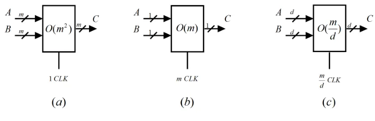
Bit-parallel Multipliers:
In this multiplier the inputs are being applied in word format with length ofm
and the output will be the same word length. The modular reduction is applied
at the same time to obtain the field element as output. The area complexity in
2.4. FiniteFieldMultipliersInAES-GCM 23
Bit-Level Multipliers:
Both multiplicand and multiplier are fed bit by bit through the shift register to
the multiplier input. There are two methods of applying the digits, MSB-first
and LBS-first. The area complexity is O(m) and requires m clock cycles for completion. Block diagram of bit-level multiplier is shown in Figure 2.2.b.
Digit-Level Multiplier:
In this method, the operands are divided intok digit length to be applied to the multiplier input . The area complexity is O(km) and required time for com-pletion is m
k clock cycles. Block diagram of digit-level multiplier is shown in
Figure 2.2.c.
Figure 2.2: Block Diagram of Multipliers a. Parallel b. Bit-level c. Digit-level
2.4.1 Low Complexity Multiplier inGF(2m)
In this section, we have an overview on a low complexity bit-parallel multiplier.
Therefore, the type of the chosen multiplier contributes towards the area and
operating frequency of the said module. The authors in [31] have shown an
approach towards low complexity bit parallel multiplier which will be used in
the following sections for the purpose of fault analysis.
They have shown thatC = AB ∈GF(2128) can be written as
c = (L+QTU)b (2.10)
Where b = [b0,b1,· · · ,bm−1]T and T denotes transposition of vector. L and Uare two Toeplitz matrices whose elements consist of ais which are the
coor-dinates of A. L is m× m lower triangular matrix and U is (m− 1)× m upper triangular matrix shown in Figure 2.3.
Figure 2.3:Demonstration ofL,U, andbin Matrix Presentation.
Qis called the reduction matrix which is (m−1)×mand could be found through the following relationship
α ↑= Qα mod F(α), (2.11)
2.4. FiniteFieldMultipliersInAES-GCM 25
Using (2.11), one can obtain the reduction matrix Q for the GCM in order
to figure out the single and multi-bit parity-based fault detection scheme.
As-suming α is the root of irreducible polynomial, then f(α) = 0 and we could rewrite (2.5) as follows
α128 +α7 +α2 +α+1 =0. (2.12)
As in the finite field, −1 = +1 then one can derive the following equation
α128 =
1+α+α2 +α7. (2.13)
Then, the first row of the reduction matrixQis obtained as follows
α128 =
"
1 1 1 0 0 0 0 1 0 · · · 0
#
| {z }
1×128
1 α α2 ... α127 (2.14)
αi+128 = αi +αi+1 +αi+3 +αi+8 f or 1 ≤i ≤ 120
α129 = α+α2 +α3 +α8
...
α248 = α120 +α121+α122 +α127
(2.15)
We can outlineα249 as follows
α249 =α121 +α122 +α123 +α128. (2.16)
Substitutingα128 from (2.16), one can find
α249 = 1+α+α2 +α7 +α121 +122 +α123
...
α253 = α4 +α5 +α6 +α11 +α125 +α126 +α127
(2.17)
As the final term is 2m−2= 254, then forα254 by using (2.13) we obtain
α254 =
1+α+α2 +α5 +α6 +α12+α126 +α127 (2.18)
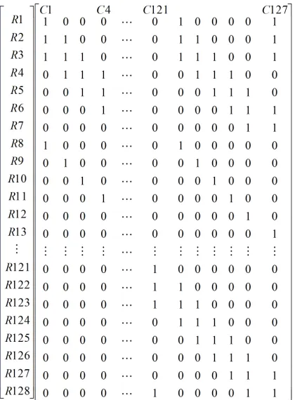
Therefore, the Q matrix could be written using (2.13) as shown in Figure 2.4,
whereR1to R127 andC1to C128 denote the row and column numbers respec-tively.
From completed Q matrix, the QTcould be written as shown in Figure 2.5.
2.5. FaultDetectionInMultiplier 27
Figure 2.4: Demonstration ofQin matrix presentation
c0 c1 ...
cm−1
=(L+QTU)
b0 b1 ...
bm−1
(2.19)
Hereafter, we name matrix E as E = L + QTU. As in the GCM module, one of the multiplicands is always power of the Hash Key H, then L = z(H) and U =g(H); Therefore, E is a function of H e.g. F = w(H). In the equation c = Eb, we realize that the output of multiplier will be the function of H and b. Thus, we use this characteristic to outline parity prediction module in terms
of the GCM elements and then define the single or multi-bit parity prediction
scheme in the entire GCM module in Chapter 4.
2.5
Fault Detection In Multiplier
multipli-Figure 2.5: QT demonstration 128×127
ers i.e., [7] [21] [9] [16] [3] [30] which demonstrate different methods of fault detections. In this section we review briefly the related ones.
In [30], the authors propose fault detection architectures for GF(2m) multi-pliers of both bit-parallel and bit-serial types. The polynomial basis is used to
represent the field elements. They develop parity prediction schemes for
detect-ing errors due to sdetect-ingle and certain multiple faults durdetect-ing the multiplication
op-eration in the field. Fault detection architectures for traditional and bit-parallel
multipliers are presented. Explicit formulations for parity predictions of three
irreducible polynomials, namely, equally spaced polynomials, trinomials, and
tech-2.5. FaultDetectionInMultiplier 29
niques to develop fault detection architectures for both MSB-first and LSB-first
bit-serial multipliers. The actual parity of the multiplier output is computed by
the Binary Tree of XOR (BTX) gates. The predicted parity is calculated based on the coordinates of the input and characteristics of finite field addition and
multiplication. Then, the outputs of these two parities are compared to detect
the faults. The double parity prediction method is also discussed given the
par-ity of the both inputs to the multiplier is known. The parpar-ity prediction block
uses both parities and the coordinates of the input to generate the double parity
prediction bits that will be compared with the actual parity bits of the multiplier
output to indicate Pass or Fail signal.
In [9], the paper provides the concurrent error detection scheme for
all-one polynomial to protect the encryption and decryption process against both
faults and attacks. To accomplish, The concept of REcomputing with Shifted
Operands (RESO) is selected.The RESO scheme employs time redundancy.
Assuming function F(x) to be a function unit and the functionG(x) are related by be G−1(F(G(x))) = F(x) for all input x. The results of two computations are compared to indicate existence of error. The proposed method needs two
additional clock cycles.
In [3], the selected approach is based on the multiple parity bits and its
effect on area overhead and error detection probability. The paper discusses the multiple bit errors in bit parallel and bit serial polynomial basis multipliers
approach, the m bit input is divided into k parts with one parity bit for each, then the multiple parity prediction scheme is used to conduct the comparison
of predicted and actual blocks to detect any errors. The author demonstrates
that in the bit-serial implementation of GF(2163) PB multiplier using 8 parity bits, the area overhead of 10.29% and probability of 0.996 are obtained. This
Chapter 3
Single bit fault detection in GCM
3.1
Fault Detection Scheme
In this chapter, we introduce a novel single-bit parity prediction method in the
GCM loop. The parity prediction scheme is outlined and extended to include
the coordinates of the Ciphertext rather than the coordinates of the input to
the multiplier. The parity prediction scheme is derived using the properties of
GF(2128) with f(x) = x128 + x7 + x2 + x+1 as irreducible polynomial. Then, we compare the predicted and actual parities in order to detect the faults in the
GCM loop. For the purpose of fault detection in the GCM module, we assume
that the AES encryption part of the module is fault free or its fault could be
verified by known methods discussed in Chapter 2. Thus, our main concern
will be the fault detection in theGHAS H function of the GCM module.
As shown in Figure 2.1, the output of theGHAS H function isXi whose
par-ity can be calculated using Binary Tree of XOR(BT X) gates or Linear
back Shift Register (LFS R) to generate pXi. We need to predict the parity of multiplier output Xi depicted as ˆpXi to compare with the actual parity pXi in order to generate PASS or FAIL signal as error indication output.
Let’s start with the sum module of Figure 2.1. The sum module denoted by
⊕ adds two elements in GF(2128) which is 128 2-input XOR gates to perform additions overGF(2). The sum result is the bitwise XORofXi−1 andCi shown
as
Di = Xi−1 +Ci = (x0 +c0, . . . , x127 +c127) ∈ GF(2128). (3.1)
Let pXi−1 and pCi denote the parity bit ofXi−1 = Yi andCirespectively. To obtain the parity of the result pD overGF(2128) one can write:
pDi = 127
X
i=0
(yi +ci) =
127
X
i=0
yi +
127
X
i=0
ci =pXi−1 + pCi. (3.2)
Equation (3.2) shows that the parity will be saved in the sum module and
remains intact during the operation. The output of sum module denoted by
Xi−1+Ci is applied to the multiply module depicted as⊗to perform
multiplica-tion byHash Key H overGF(2128) mod F(α) whereαis the root of irreducible polynomial f(x). Next, we figure out the parity prediction method in the mul-tiply module in terms of the GCM elements e.g., Ci and H. The parity of the
multiplier output denoted by Xi will be a function of its input operands Di and
3.1. FaultDetectionScheme 33
pXi = f(Di, H) = f(pDi, pH). (3.3)
This formulation shows that the parity of the output is a function of the
parity of input CiphertextCi and the parity of Hash Key H.
3.1.1 Parity for the powers of the Hash Key(H)
In this section, we focus on multiplication inGF(2128) to implement the parity prediction scheme for the multiplier in the GCM. Authors in [30] have shown
the following characteristics of GF(2m) which we use to outline our fault de-tection strategy over AES-GCM module.
Let A ∈ GF(2128) andαbe a root of irreducible polynomial f(x), then each element of the field could be written in terms ofαas
A =
127
X
i=0
aiαi ai ∈ {0,1} (3.4)
Where ais are the coordinates of Awith respect to polynomial basis.
The finite field multiplication of two elements A and B in GF(2128) could be represented as
A mod F(α) = A·
127
X
i=0
bi ·((Aαi)mod F(α)) =
127
X
i=0
bi ·Z(i) (3.5)
Z(i) = α·Z(i−1)mod F(α) f or1≤ i ≤ 127, Z(0) = A. (3.6)
In the AES-GCM module shown in Figure 2.1, theHash Key His encrypted initially and remains constant throughout the Tag generation process. Using
this feature, we propose a parity prediction method in the GCM loop in terms
of the parity ofH(j)sand parity of CiphertextCiin order to have low complexity
and space overhead. To Calculate the parity prediction of the multiplier output,
we need to compute the parity of H(j)s by using (3.6) as
H(j) = α.H(j−1)mod F(α) (3.7)
H and H·αcould be written in terms of the its coordinate as follows
H = h0 +h1α+· · ·+h127α127
H·α = h0α+h1α2 +· · ·+h126α127 +h127α128
(3.8)
Since α is a root of irreducible polynomial and F(α) = 0, then α128=α7 +
α2 +α+ 1. Therefore, substitution of α128 with its equivalent in (3.8) obtains
H·αmod F(α) as
H(1) =h0α+h1α2 +· · · +h126α127 +h127(α7 +α2 +α+1) (3.9)
3.1. FaultDetectionScheme 35
h(1) = [h127, h0+h127, h1+h127, h2, h3, h4, h5, h6+h127, h7, . . . , h126]T. (3.10)
From (3.10) we conclude the important parity relationship between powers of
Has
pH(1) =pH(0) +h127
pH(2) =pH(1) +h126 ...
pH(127) =pH(126)+h1.
(3.11)
3.1.2 Parity Prediction for the Multiplier in the GCM
The authors of [30] have derived the parity prediction formula for the
multi-plication of two arbitrary field elements which can be applied to the multiplier
inputs Di and H in the AES-GCM module as follows
ˆ
pXi = 127
X
i=0
dipX(i) =
127
X
i=0
dipH(i). (3.12)
The formulation of (3.12) constructs the foundation in parity prediction of
the AES-GCM module in this thesis. As the Hash Key H does not change during the encryption process, the values of pH(i) could be precomputed and
Next, we calculate the predicted parity by performing XOR operation on outputs as shown in Figure 3.1. The predicted parity can be compared with the
actual parity of the output to verify any odd numbers of stuck at-0 or stuck at-1
fault happened in the circuit under test (CUT).
Figure 3.1:Parity prediction scheme
3.1.3 Fault Detection in the GCM Loop
We need to extend fault detection to include the parity of the actual Ciphertext.
Therefore, we rewrite Di in terms of the inputs of sum module. Thus, we can
rewrite (3.12) at the ithclock cycle as follows:
Xi = (Xi−1 +Ci) pH =(Yi−1 pH)+(Ci pH). (3.13)
3.1. FaultDetectionScheme 37
the contents of Y register and CiphertextCi at theith clock cycle respectively.
Therefore, the parity prediction of theGHAS H function at the ith clock cycle in the AES-GCM loop can be found using (3.14) as follows
ˆ
pXi = 127
X
j=0
yjpH(j) +
127
X
j=0
cjpH(j). (3.14)
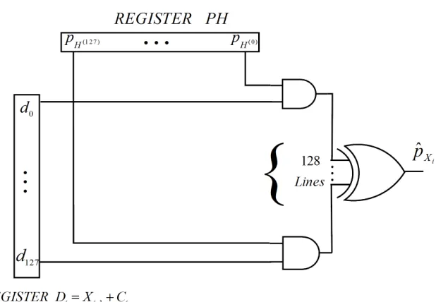
where Yi−1 = (y0, . . . , y127) and Ci = (c0, . . . , c127). Figure 3.2 shows the AES-GCM parity prediction scheme which is a realization of the key
formula-tion presented in (3.14).
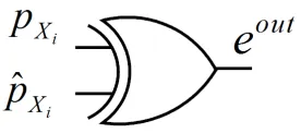
The error indicator eout is generated using one XOR gate as shown in
Fig-ure 3.3. At every clock cycle the existence of error will be verified by detecting
logic 1 ateout. All needed at the output of the multiplier is to compute its parity
Figure 3.2:AES-GCM loop parity prediction scheme
Chapter 4
Multiple Parity Bit Fault Detection
Architecture
4.1
Introduction
In this chapter we introduce a novel matrix-based multiple parity bit fault
de-tection method in the AES-GCM loop. As shown in [31] and discussed in
Section 2.4.1, the multiplier output Xi in Figure 2.1 can be represented as
Ed = (L+QTU)d, where E and d represent the H and Di inputs to the
multi-plier respectively.
First, we define the matrix E in terms of H and outline single and multiple bit parity fault detection. Next, matrix-based CRC is introduced and related fault detection scheme is investigated.
4.2
Matrix-Based Parity Prediction Scheme in GCM Loop
4.2.1 Matrix-Based Single Parity Bit Scheme
In this section, we define the matrix- based parity prediction scheme for the
multiplier output. As the parity of the multiplier output Xi = C is defined by
pC = P127i=0 ci, we show the matrix presentation of the output parity as
pC =oc, (4.1)
wherec= [c0 c1 . . . c127 ]Tand o =[ 1 1 · · · 1] is a 1×128 all one row vector. For the purpose of output parity prediction, we need to use the
coordinates of the inputs to the multiplier which can be obtained from matrix
E as follows
ˆ
pC = (oE)d, (4.2)
where d= [d0 d1 · · · d127]
T, oE is a function ofH which is denoted as
[ 1 1 · · · 1][ f(H)]128×128. Thus, the parity prediction of the output will be function of H and Di, i.e,
ˆ
pC = f (H,Di), (4.3)
To outline the parity prediction architecture, we focus on computing the
outcome of oE instead of finding matrixE. Therefore, our new approach is to
multi-4.2. Matrix-BasedParityPredictionScheme inGCM Loop 41
plication.
The MatrixQTshown in Figure 2.4 is multiplied byUin order to obtain QTU.
Let the number of 1s in the jth column of QT be rj. Then each element of U
in the jth row repeats rj times in each column of QTU. For example, the first
column of QT contains 4Ones(1s) which causes each element of Uin the first row to appear 4 times in each column of QTU. The first column of Uis all 0s
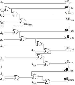
which does not have any effect once added to the first column of L. Thus, the content of the first element of oE denoted by oE(1,1) is the parity of the first
column ofL that is pH.
The second column of U has h127 in the first row and all 0s for the rest of the column. Therefore, h127 appears four times in the second column of QTU which has no effect on the parity of the second column of QTUbecause of the even numbers of the repeats ofh127 that cancels offthe effect. The value of the second element of theoE denoted byoE(1,2) is the parity of the second column
ofL which is pH +h127. This pattern continues up to the element 122 with the
correspondingoE(1,122) =oE(1,121) +h7.
oE(1,1) = pH
oE(1,j) = oE(1,j−1)+hm−(j−1) f or2 ≤ j ≤122
oE(1,123) = h0 +h1 +h2 +h3 +h4 +h5 +h127
oE(1,124) = h0 +h1 +h2 +h3 +h4 +h126 +h127
oE(1,125) = h0 +h1 +h2 +h3 +h125 +h126+h127
oE(1,126) = h0 +h1 +h2 +h124 +h125 +h126 +h127
oE(1,127) = h0 +h1 +h123 +h124 +h125 +h126 +h127
oE(1,128) = h0 +h122 +h123 +h124 +h125 +h126,
(4.4)
whereoE(1,k) contains the pH(k). Figure 4.1 shows the logic implementation of
the matrixoE which is stored into the register oE.
The register oE can be used for single parity prediction and fault detection
in the AES-GCM loop using the same architecture shown in Figure 3.2. Thus,
the register oE replaces register pH while the rest of the scheme remains the
same for the purpose of fault detection.
4.2.2 Matrix-Based Random Parity Bit Scheme
In this section, we extend the parity prediction of (4.2) to double and then to
multiple parity bit scheme for the purpose of fault detection. Therefore, we
4.2. Matrix-BasedParityPredictionScheme inGCM Loop 43
Figure 4.1:Implementation of Matrix(Register)oE
obtainkparity bits in our scheme as follows
ˆ
pC1
ˆ
pC2 ...
ˆ
pCk
=
1 · · · 0
1 · · · 0
... · · · ...
0 · · · 1
| {z }
O0(k×128)
whereO0can be a random matrix. The selected pattern of O0 depends on
com-plexity and fault coverage in the fault detection module. Double parity
predic-tion block diagram is shown in Figure 4.2.
Figure 4.2:Block Diagram of Double Bit Parity.
4.3
Matrix-based CRC for Multi-Bit Parity Fault Detection
4.3.1 Brief review on CRC
CRC (Cyclic Redundancy Check) [8] [32], is a code for detecting errors in dig-ital networks, data transmission, and storage devices. CRC has been adopted to detect changes to data, but no error correction is made through it. In theCRC, certain number of bits will be added to the message that is called checksum to
be transmitted together with the message. Then, the checksum of the received
message is computed and compared with the sent one to detect possible errors
4.3. Matrix-basedCRCforMulti-BitParityFaultDetection 45
CRC treats the message as a polynomial inGF(2m). It is obtained by com-puting the remainder of dividing the message polynomial into the divisor
(gen-erator) polynomial. Fork−bitCRC, the generator polynomial must be of degree
k. Let denote the message as m(x) = mm−1xn−1 +· · · +m1x+m0, the generator polynomial as G = g(x) = gkxk +· · ·+ g1x+1; Then, we outline the CRC of
m(x) as follows:
m(x)mod g(x) =CRC(m). (4.6)
For k−bitCRC, the check value is k bits and the generator polynomial has (k+1) terms. A k−bit CRC is capable of detecting all errors of length≤ k. If
G is x+1, then the CRC denoted asCRC −1 is called the parity bit to detect single bit or odd number of errors. Most commonly used CRCs are CRC-12,
CRC-16, and CRC-32.
4.3.2 Matrix-Based Double Bit Parity CRC
In this section, we define the matrix-based CRC fault detection scheme using the multiple parity bits for the multiplier module. Then, we extend the
polynomial of degree 127 as shown below:
cTx = c(x)
c0 c1 . . . c127
T 1 x ... x127
= c(x),
(4.7)
wherec(x) = c0+c1x+. . .+c127x127. For the purpose of double parity prediction scheme, the generator polynomial is g(x) = x2 + x + 1. As the degree of the generator polynomial is 2, the resulting remainder would be ax +bwhich creates two bit parity for the purpose of fault detection. From (4.7), we realize
that the coordinates of the multiplier output c(x) can affect the output parities after calculation ofx mod g(x) which is independent of the output coordinates and can be used as constant pattern for parity generation and prediction. Thus,
we conclude the following equation
c(x) mod g(x) =cT.(x mod g(x)) (4.8)
4.3. Matrix-basedCRCforMulti-BitParityFaultDetection 47 1 x x2 x3 x4 ...
mod g(x) =
1 x x+1
1 x ... = 1 0 0 1 1 1 1 0 0 1 ... ... " 1 x #
= pCRC
"
1
x
#
(4.9)
Using (4.9), we realize a very important approach towards the proposed fault
detection by introducing theCRC of double bit parity matrix aspCRC−2 . Thus, form (4.9) and (4.8) the double bit parity of the output is computed as follows
cT.pCRC−2
"
1
x
#
= [b ax] = [pC1 pC2]
"
1
x
#
a,b ∈ {0,1} (4.10)
To calculate the [pC1 pC2], one should multiply cT by each column of pCRC−2 separately. The hardware realization of this operation is bitwiseANDof multiplier outputcT with column 1 and 2 of pCRC−2 . Then, we compute each
individual parity by performing XOR operations on the output bits to obtain
Figure 4.3:Hardware implementation of Double Bit Parity Generator on multiplier output.
4.3.3 Matrix-Based Double Bit Parity Prediction CRC
In this section, we outline the parity prediction scheme using the matrix-based
4.3. Matrix-basedCRCforMulti-BitParityFaultDetection 49
As shown in Figure 4.5, the inputs to the GCM multiplier are H and Di. Thus,
matrix O0kE represents kbit parity prediction with regards to the multiplier in-puts H and Di which is denoted by d(x) in polynomial basis. Using (4.9), we
define the output parity prediction as follows
(O0kE)d = pˆ(CRC−k)d
d = d0 d1 ... d127 , (4.11)
where ˆp(CRC−k)d = [ ˆp0 pˆ1 · · · pˆk]T. As we are investigating double parity bit fault detection, we replace the O0k with pT(CRC−2). Thus, we use (4.11) to
obtain the double bit parity prediction as follows
(pT(CRC−2)E)d= [ ˆpC1 pˆC2]. (4.12)
The computation ofpT(CRC−2)E is given in appendixA which could be easily implemented in hardware. In order to detect faults, we need to compare the
actual and the predicted parities to generate PASS or FAIL signal which is
calledeout. If the compared parity pairs are the same, there is no error andeout =
which is the ”k−bit XOR Comparator” block depicted in Figure 4.5.
Figure 4.4: Error signal generator.
4.3.4 Matrix-basedk Bit Parity Fault Detection(k >2)
For the kbit matrix-based fault detection scheme, one needs to define the gen-erator polynomial which is degree of k. The generator polynomial can be irre-ducible which gives the maximum number of checksums or remainders.
There-fore, we have the maximum code length of 2k −1 and the code can detect all
one bit and double bit errors [18]. To improve the error detection capability,
we choose the generator polynomial to be g(x) = (x +1)g0(x) where g0(x) is primitive polynomial. The order of g0(x) is k − 1 and total code length will be 2k−1 −1, in this case all single, double, triple, and all odd number of errors
could be detected [36]. Table 4.1 illustrates the irreducible polynomials for the
CRC up to the degree 5. Higher degree polynomials can be found in [18]. After selection of the generator polynomial, we need to determine the
pat-tern of matrix pCRC−k with regards to chosen polynomial. To accomplish, we
4.3. Matrix-basedCRCforMulti-BitParityFaultDetection 51
k Irreducible Polynomial
1 x+1,x
2 x2+x+1
3 x3+x2+1,x3+x+1
4 x4+x3+x2+x+1,x4+x3+1,x4+x+1
5 x5+x4+x3+x2+1,x5+x4+x3+x+1,x5+x3+x2+x+1,x5+x4+x2+x+1,x5+x3+1,x5+x2+1
Table 4.1: Irreducible Polynomials to the degree 5.
rj = xjmod g(x) for 0 ≤ j ≤ 127. Then, the remainder set {r1, r2, . . . , r128} constructs the rows 1to128 of the parity matrix pCRC respectively. Table 4.2
shows the pattern for selected polynomials.
Polynomial x2+x+1 x3+x+1 x4+x+1
pCRC 0 1 1 0 1 1 ... ...
0 0 1 0 1 0 1 0 0 0 1 1 1 1 0 1 1 1 1 0 1 ... ... ...
0 0 0 1 0 0 1 0 0 1 0 0 1 0 0 0 0 0 1 1 0 1 1 0 1 1 0 0 1 0 1 1 0 1 0 1 1 0 1 0 1 1 1 0 1 1 1 1 1 1 0 1 1 0 0 1 ... ... ... ...
Table 4.2:pCRCMatrix pattern for selected polynomials.
4.3.5 Fault Detection Architecture
At this stage, we load each column of pCRC−k matrix into k separate registers
called p(j)CRC−k where jindicates the jth column and 1 ≤ j ≤ k. pCRC−k does
permanently in the GCM module. Then, by implementing (4.10) and (4.8),
we figure out the actual parities and predicted k- bit parities to compare and generateeout signal.
To extend the fault detection to the entire GCM loop, we outline the block
diagram of the model using k−bit parity prediction scheme in Figure 4.5. In this scheme, we take into account the coordinates of the Ciphertext which is the
main element of the GCM module in the GHAS H function. As illustrated in Figure 4.5, registerCi represents the coordinates of theith Ciphertext, register
Xi is the current multiplier output, register Yi−1 is the content of Xi−1 +Ci. The
4.3. Matrix-basedCRCforMulti-BitParityFaultDetection 53
Testing and Simulation
5.1
Introduction
Since we have used the information redundancy technique in our fault
detec-tion scheme, a parity based Concurrent Fault Detecdetec-tion (CFD) has been inves-tigated. In this chapter, we introduce the simulation testbench for the proposed
matrix-based multiple bit parity prediction CRC discussed in Chapter 4. First, we implement the GCM scheme using VHDL language. Then, Modelsim SE
10.3 is applied to simulate the design. The fault injection is implemented in the
body of the main program using the VHDL language. TCL stimulus package
is employed to inject the faults and monitor the outputs. The different instances of single, multiple bit, transient, and permanent stuck-at faults are injected into
the scheme and the results are investigated and further elaborated in the
follow-ing sections.
5.2. VHDL Implementation ofFaultModel 55
5.2
VHDL Implementation of Fault Model
The main part of the GCM is multiplier module which is implemented through
equationC =(QTU+L) [31]. We can write the multiplier output of the GCM module shown in Figure 4.5 as
xi =(L +QTU)di (5.1)
All elements of QTU and L are calculated and constructed in terms of the
coefficients of H. MatrixQTU is depicted in Figure 5.1. Matrix E represents (L+QTU) which generates the multiplier output by performing multiplication E.di over GF(2128) where di = (ci + xi−1) which are discussed in Chapter 2.
Therefore, we need to define all the matrices in terms of the VHDL language
which is demonstrated in appendix A.
For the purpose of fault injection and fault detection, the implementation
of all matrices and vectors must be done individually in VHDL to give us the
gate level access for the GCM module. Otherwise, we will not be able to cover
entire hardware to inject the faults. To accomplish this approach, we introduce
and add Element−S tuck−at−f ault to all elements of each matrix and vector
separately as follows