ISSN(Online): 2319-8753 ISSN (Print): 2347-6710
International Journal of Innovative Research in Science,
Engineering and Technology
(An ISO 3297: 2007 Certified Organization)
Website: www.ijirset.com
Vol. 6, Issue 6, June 2017
Study and Development of an ASS for the
Surface Resistivity Measurement of RPC
Detector Electrodes
A. Pandey1, A. Kumar2, N. Marimuthu3, M. K. Singh4, V. Singh*5 V. S. Subrahmanyam6
Ph. D. Student, Department of Physics, Institute of Science, Banaras Hindu University, Varanasi, UP, India1
Ph. D. Student, Department of Physics, Institute of Science, Banaras Hindu University, Varanasi, UP, India2
Ph. D. Student, Department of Physics, Institute of Science, Banaras Hindu University, Varanasi, UP, India3
Ph. D. Student, Department of Physics, Institute of Science, Banaras Hindu University, Varanasi, UP, India4
Assistant Prof., Department of Physics, Institute of Science, Banaras Hindu University, Varanasi,UP, India5
Assistant Prof., Department of Physics, Institute of Science, Banaras Hindu University, Varanasi,UP, India6
Abstract: India-based Neutrino Observatory (INO) is planning to use ~30,000 Resistive Plate Chamber (RPC) detectors of size 2m x 2m. Each resistive plate chamber is made up of glass electrodes whose surface resistivity of the order of 1012 ohm/square, along with two readout panels. A thin layer of conducting graphite paint coating is applied on the outer surfaces of the electrodes in order to make electrode slight conducting. For the optimal performance of the detector, the surface resistivity should be uniform throughout the surface area of the electrodes. Therefore, information about the uniformity and the surface resistivity value helps us in improving the quality of the detector performance. We developed an automatic scanning system (ASS) for the 2m x 2m electrode, which is first time developed in any Indian laboratories. In this paper, we report the performance of the ASS in terms of efficiency and accuracy and future utility of the system.
KEYWORDS:INO, RPC, Arduino Motor Shield
I. INTRODUCTION
ISSN(Online): 2319-8753 ISSN (Print): 2347-6710
International Journal of Innovative Research in Science,
Engineering and Technology
(An ISO 3297: 2007 Certified Organization)
Website: www.ijirset.com
Vol. 6, Issue 6, June 2017
II. EXPERIMENTAL DETAILS
Arduino consists of both a physical programmable circuit board and a piece of software. Arduino is a microcontroller board, which is operated through embedded coding in C language on Arduino IDE (Integrated Development Environment) software that runs on the computer and act as a platform. All the required commands used to write, compile and upload computer code to the physical board in the IDE [5]. There are several types of microcontrollers available by the Arduino, but in the automation module ATmega 328P Arduino board, as shown in Figure 1(a), has commonly been used. This Arduino board has 32kb of flash memory of which 0.5kb is used by boot loader, 2kb of SRAM and 1kb of EEPROM. The operating voltage of the board is 5V and it contains 6 PWM digital I/O pins as well as 6 analog input pins [6]. For automation purpose, Arduino motor shield, as shown in Figure 1(b), has also been used along with microcontroller. This Arduino motor shield contains two L293D and one 74HC595, motor drivers. The shift register expands 3 pins of the Arduino to 8 pins to control the direction for the motor drivers [7]. The output enable of the L293D is directly connected to the pulse width modulation (PWM) outputs of the Arduino. The motor shield is able to drive 2 servo, 2 stepper and 4 DC motors, which has been used in the automation. Automatic scanning system performs the scanning using 4 bidirectional DC motors. Movement of all the four DC motors in order to accomplish the scanning purpose has been done successfully using coding to the IDE platform provided by Arduino. Block diagram and actual photograph of Automatic Scanning System(ASS)[8] are shown in Figures 1 (c) and (d), respectively.
(a) (b)
(c) (d)
Fig. 1: (a) ATmega 328P Arduino board, (b) Arduino motor shield, (c) Block diagram of ASS and (d) photograph of automatic scanning system for 2m x 2m size electrodes (ASS).
II (a). MOTION CONTROL OF MOTORS
ISSN(Online): 2319-8753 ISSN (Print): 2347-6710
International Journal of Innovative Research in Science,
Engineering and Technology
(An ISO 3297: 2007 Certified Organization)
Website: www.ijirset.com
Vol. 6, Issue 6, June 2017
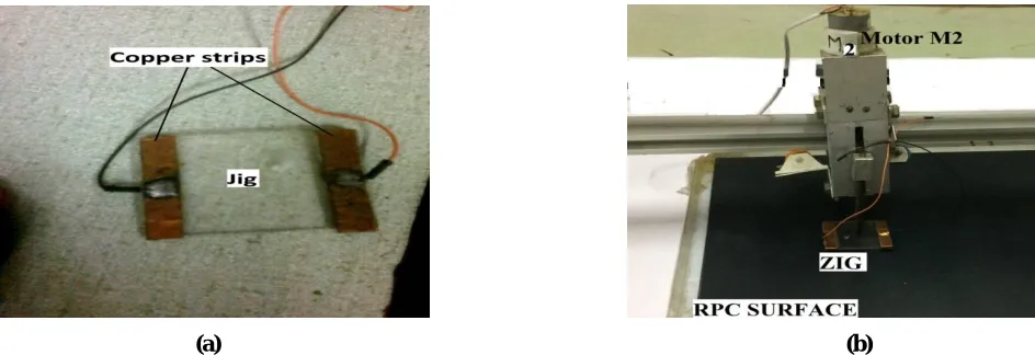
the Cu tape and plastic, as shown in Figure 2(a). Motion M2 that control the vertical (up and down) motion of the jig and complete assembly is shown in Figure 2(b). Motor M1 controls the motion of the jig-subunit along the x - axis. As soon as the jig completes the surface resistivity measurement of one line having width 5 cm over the glass electrode, both motors M3 and M4 move the jig along the y–axis simultaneously. These complete sets of steps repeat until the end of the glass electrode. In this manner, jig completes the measurement of surface resistivity of the whole surface of the electrode. Movement i.e., step size and speed of DC motor is controlled by library named as <AFMotor.h>, which is included at the beginning of the program.
(a) (b)
Fig. 2: (a)Photograph of the Jig and (b) Vertical motion subunit of Automatic Scanning System.
II (b). MEASUREMENT OF SURFACE RESISTIVITY
Principle of voltage divider is applied for the voltage of 5V, supplying from ARDUINO, which is divided between two resistances, one is known resistance (Rk) and the other one is the resistance across the jig (Rj), which is using for probing the resistance value as shown in Figure 3. Coding has been done in order to read the voltage value (Vout) across the jig, which is coming out from analog pin of microcontroller when it is placed over the ELECTRODE surface. In addition, Arduino also measures the current flow through the jig. Hence, the resistance value across the jig length can be calculated with the help of Eqn. (1). Both the information is stored in the computer for further processing using “Cool Term”, which transfers the data containing resistance values from the ARDUINO UNO.
Vout = Rk / (Rk + Rj) x Vin. (1)
Where, Rk and Rj are known and jig resistances, respectively.
II (c). AUTOMATIC DATA STORAGE AND DISPLAY
ISSN(Online): 2319-8753 ISSN (Print): 2347-6710
International Journal of Innovative Research in Science,
Engineering and Technology
(An ISO 3297: 2007 Certified Organization)
Website: www.ijirset.com
Vol. 6, Issue 6, June 2017
III. RESULTSANDDISCUSSION
The ASS is very effective that speedup the surface resistivity measurement of electrodes with high accuracy. Few experiments have been performed to test the ability and accuracy of the ASS is following.
III (a). ERROR IN RESISTANCE MEASUREMENT
Fig. 3: Circuit diagram for resistance measurement.
To know the variation in the measured value of surface resistivity, we performed a series of following experiments. Experiment - 1: We measured the resistance value of the known resistance (221.5 kΩ) at least 1000 times using the automatic scanning system (ASS). The obtained data is fitted with the Gaussian function and their parameters are also mentioned as the inset. We obtained the resistance value of 221.4±0.09 kΩ as shown in Figure 4. In this measurement constant amplitude current having 3 seconds interval was applied to the jig and during the measurement its movement was fixed. The observed data points are not in the expected manner due to the low statistics. The standard deviation from the mean value is 1.47 k.
(a) (b)
Fig. 4: (a) Distribution of measured resistance values of the Experiment – 1 and (b) the same for the case of Experiment – 2
ISSN(Online): 2319-8753 ISSN (Print): 2347-6710
International Journal of Innovative Research in Science,
Engineering and Technology
(An ISO 3297: 2007 Certified Organization)
Website: www.ijirset.com
Vol. 6, Issue 6, June 2017
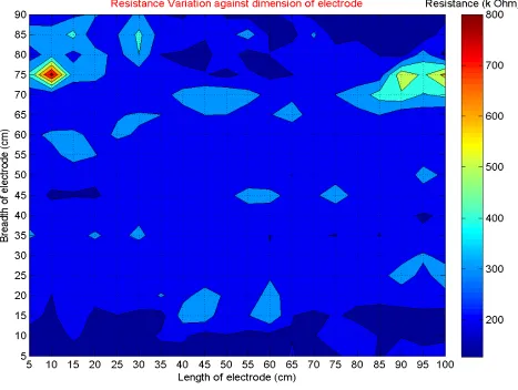
III (b). CONTOUR PLOT OF SURFACE RESISTIVITY OF 100 cm 90 cm GLASS ELECTRODE
To check the performance of the automatic scanning system (ASS), measurement of the surface resistivity of the graphite coated glass electrode having dimension 100 cm 90 cm has been performed. A jig of 5 cm 5 cm is used for the above experiment. The obtained results are shown in Figure 5 in terms of the contour plot. The colour code for the resistance value is also shown in unit of k. Figure 5, reflects the quality of graphite coating on the glass surface and its uniformity of distribution.
Fig. 5
:
Contour plot of measured surface resistivity of 100 cm 90 cm dimension RPC electrode by automatic scanning system.
ISSN(Online): 2319-8753 ISSN (Print): 2347-6710
International Journal of Innovative Research in Science,
Engineering and Technology
(An ISO 3297: 2007 Certified Organization)
Website: www.ijirset.com
Vol. 6, Issue 6, June 2017
IV. SUMMARY AND OUTLOOK
From the above results and discussion, we may summaries the research article as following:
1) The developed automatic scanning system is used for the measurement of surface resistivity of RPC detector’s electrodes. It is enough efficient and accurate to perform the measurement in short period. Use of very high RPM motor may speed up the job.
2) It is found that resistance of electrodes is mostly uniform i.e. more than 87% area, in the range of 200 KΩ - 300 KΩ. 3) Some strong variation of surface resistivity (~750 k) is observed in the contour plot in a small area i.e. less than a quarter percent, of the electrode. This variation will not affect the efficiency of the RPC detector because efficiency will get affected only if the almost similar non-uniform area having variation beyond the mentioned range will exactly match in both side electrodes.
4) We are still working for making better automatic scanning system in which we can control the motor shield using wireless communication so that we can operate the whole setup remotely and comfortably.
5) We are also working on the more advance application of the ASS in terms of RPC detector efficiency and calibration measurement.
ACKNOWLEDGMENT
Authors are grateful to the Department of science and technology (DST), New Delhi for providing financial support and the INO Collaboration for their valuable discussion and suggestions.
REFERENCES
[1] Design and Characterization Studies of Resistive Plate Chambers by S. Bheesette, Thesis (2009) [2] M. K. Singh et al IJIRSET 04 (10), 10035 (2015)
[3] S. Shree et al. DAE Nucl. Phys. Proc. 59, 854 (2014) [4] A. Pandey et al. DAE Nucl. Phys. Proc. 61, 1060 (2016)
[5] Arduino user guide web link: https://www.arduino.cc/en/Guide/HomePage
[6] Arduino motor shield user guide link: https://cdn-learn.adafruit.com/downloads/pdf/adafruit-motor-shield.pdf [7] A. Kumar et al. DAE Nucl. Phys. Proc. 60, 1008 (2015)
BIOGRAPHY
[1] [2] [3] [4] [5] [6] [1]: Akash Pandey, [2]: Abhishek Kumar, [3]: N. Marimuthu, [4]: Manoj Kumar Singh, [6] Dr. Venktesh Singh [Corresponding Author], [5]: Dr. V. S. Subrahmanyam