Design and Analysis of Horizontal Pressure
Vessel and Thickness optimisation
Anandhu P D 1, Avis A 2
P.G. Student, Department of Mechanical Engineering, Sree Naryana Gurukulam College of Engineering, Kadayiruppu,
Kerala, India1
Assistant Professor, Department of Mechanical Engineering, Sree Naryana Gurukulam College of Engineering,
Kadayiruppu, Kerala, India2
ABSTRACT: This project deals with design and analysis of horizontal pressure vessel and also thickness optimization of vessel. Pressure vessel is a container for confining fluid at elevated temperature and pressure. In the design of pressure vessel safety is the primary consideration, due the potential impact of possible accidents. Efforts are made in this project to design the pressure vessel using ASME codes & standards to legalize the design. Here we design the pressure vessel with ASME Section VIII, Division 1,2013.Finite element analysis of the pressure vessel has been done in ANSYS. Static structural analysis of the vessel has been done by applying the internal pressure, standard earth gravity, and also by fixing both the legs. Thickness optimisation of the pressure vessel is also done in ANSYS.
KEYWORDS:pressure vessel, ASME, ANSYS.
I.INTRODUCTION
A pressure vessel is defined as a container with a pressure differential between inside and outside. We can define pressure vessel as a container for confining fluid having internal energy greater than its free state. The inside pressure is usually higher than the outside, except for some isolated situations. The fluid inside the vessel may undergo a change in state as in the case of steam boilers, or may combine with other reagents as in the case of a chemical reactor. Pressure vessels often have a combination of high pressures together with high temperatures, and in some cases flammable fluids or highly radioactive materials. Because of such hazards it is imperative that the design be such that no leakage can occur. In addition these vessels have to be designed carefully to cope with the operating temperature and pressure. It should be borne in mind that the rupture of a pressure vessel has a potential to cause extensive physical injury and property damage. Plant safety and integrity are of fundamental concern in pressure vessel design and these of course depend on the adequacy of design codes. [1, 2]
The size and geometric form of pressure vessels vary greatly from the large cylindrical vessels used for high-pressure gas storage to the small size used as hydraulic units for aircraft. Pressure vessels commonly have the form of spheres, cylinders, cones, ellipsoids, torispherical, or composites of these. Some are buried in the ground or deep in the ocean, but most are positioned on ground or supported in platforms. [2, 3]
II.RELATEDWORKS
Shaik Abdul Lathuef and K.Chandra Sekhar (2012) discussed about some of the potential un-intended consequences related to Governing Thickness of shell as per ASME. Here they took the minimum thickness of pressure vessel shell to the desired requirements and also re-allocate the nozzle location to minimize the stresses developed in the shell. In this paper nozzle located at five different places and their analysis with ANSYS had been done. The new locations of the nozzle are at the left end of the shell, at the middle of the shell, at the right end, at dished end of both side. Also they calculated the stress and found from the result that the stress would be minimum at the dished end with hillside orientation. [4]
M. Pradeep Kumar, K. Vanisree (2013) they designed and analysed a high pressure frame assembly for submarine mounted EW system(Electronic Warfare System).They presented the work on Design and Implementation of Circular Cross Sectional Pressure Vessel Using Pro-E and ANSYS. According to their study the rectangle cross sectional vessel with flat end caps are not suitable for electronic warfare antenna because of the high stresses developed in it.They concluded the stresses developed in the circular cross section with hemispherical end caps are very less as compared to rectangle cross sectional vessel which is used in submarine system. Also in the circular cross section, the stresses and deflections are minimum. Design of pressure vessel done by ASME code section VIII and analysis is done by ANSYS software.[5]
V.N. Skopinsky and A.B. Smetankin (2006) they describe about the structural model and stress analysis of nozzle connections in ellipsoidal heads subjected to external loadings. They used Timoshenko shell theory and the finite element method. The features of the structural model of ellipsoid-cylinder shell intersections, numerical procedure were discussed. A parametric study of the effects of geometric parameters on the maximum effective stresses in the ellipsoid-cylinder intersections under loading was performed. The results of the stress analysis and parametric study of the nozzle connections are presented. They also concluded that the stresses due to the external loadings are secondary stresses with respect to primary stresses from the internal pressure, these stresses should be taken into consideration in a complete stress analysis for nozzle connections of a pressure vessel.[6]
III.DESIGNOFPRESSUREVESSEL
1a) Design of Shell (considering internal pressure) From ASME SEC VIII DIV 1 , UG-27. [7]
From longitudinal stress thickness t = P∗R
(2∗S∗E + 0.4∗P) =
. ∗
( ∗ ∗ . . ∗ . )= 3.96 mm
Considering the corrosion allowance ,t = 3.96 + 3 = 6.96 mm = 8 mm
From circumferential stress thickness t = ∗
( ∗ . ∗ ) =
. ∗
( ∗ . . ∗ . )= 7.974 mm
Considering the corrosion allowance, t = 7.94 + 3 = 10.974 mm = 12 mm
Internal Pressure acting on the vessel < Maximum allowable pressure . Hence the design is safe
Assume thickness t =14 mm (for t =12 mm design is not safe for external pressure)
Maximum allowable pressure = Pa = ∗
( ) =
∗
∗ . = 0.147 MPa Considering the corrosion allowance , t = 14 + 3 = 17 mm = 18 mm
External Pressure acting < Maximum allowable pressure . Hence the Design is safe
2a) Design of Ellipsoidal Head (considering internal pressure) From ASME SEC VIII ,DIV 1 , UG-32 (d)
Thickness of head t =2SE − P∗D0.2∗P = . ∗
∗ ∗ . . ∗ . = 7.94 mm Considering the corrosion allowance , t = 7.94 + 3 = 10.94 = 12 mm
2b) Design of Ellipsoidal Head (considering external pressure) From ASME section VIII division 1, UG-33(d)
Assume thickness t =14 mm
Maximum allowable external working pressure Pa = ∗
( ) =
∗
∗( ) = 0.5388 MPa
External Pressure acting < Maximum allowable external pressure . Hence Design is safe
Considering the corrosion allowance , t = 12 + 3 = 15 = 16 mm
3) Nozzle thickness calculation From ASME SEC VIII , DIV -1 , UG -45. [7,9]
Minimum nozzle thickness of N1(5 inch nozzle) = tN1 = min (ta , max (tb1 , tb2) )= min (2.11 , 18 )= 2.11 mm
Considering the corrosion allowance ,Thickness of nozzle 1 = 2.11 + 3 = 5.11 = 6 mm
Minimum nozzle thickness of N2 (8 inch nozzle) = t N2 = min (ta, max (tb1 , tb2 )) = min (3.18 , 18) = 3.18 mm
Considering the corrosion allowance, Thickness of nozzle 2 = 3.18 + 3 = 6.18 = 8 mm
Minimum nozzle thickness of N3 (20 inch nozzle) tb = min (ta,max(tb1 , tb2 )) = min (4.78,18) = 4.78
Considering the corrosion allowance tb = 4.78 + 3 = 7.78 = 8 mm
Considering the circumferential stress ta = ∗
∗ . ∗ =
. ∗
∗ . . ∗ . = 1.620 mm
Considering the corrosion allowance ta = 1.620 + 3 = 4.620 = 6 mm
Therefore nozzle thickness for manhole is t3 = max(ta, tb) = max(6,8) = 8 mm
4) Reinforcement Required for openings in Shells and Formed Heads
5 inch Nozzle with outside diameter 141.3 mm
The condition to be satisfied to have proper reinforcement is that ; A1 + A2 +A5 ≥ A
A = Total cross‐sectional area of reinforcement required in the plane under consideration A = d * tr * F + 2 * tn *tr * F ( 1 – fr1 ) = ( 129.3 *18*1 ) + (2*6*18(1-1)) = 2327.4 mm2
A1 = Area in excess thickness in the vessel wall available for reinforcement
A2 = Area in excess thickness in the nozzle wall available for reinforcement
A2 = 5*(tn - tr n)*fr2*tn = 5(6-3)*1*6 = 90 mm2
We know for proper reinforcement A1 + A2 + A5 ≥ A
A5≥ A – ( A1+A2)
A5 =cross‐sectional area of material added as reinforcement
A5 = 2327.4 – (258.6+ 90 ) = 1978.8 mm
A5 = ( Dp-d-2tn ) * te * fr4
1978.8 = (258.6 – 129.3 – 2* 6) * te *1
t e = thickness or height of reinforcing element =16.86 mm = 18 mm
Similar procedure has to be repeated for nozzle with 8 inch and 20 inch diameter
IV.FINITEELEMENTANALYSIS
Pressure vessel with 18 mm thickness has been modelled in Catia and analysed in ANSYS and then reduced the thickness of pressure vessel from 18 mm to 16 mm and then analysed further, again the thickness is reduced from 16 mm to 14 mm and analysed. Also pressure vessel with thickness 16 mm and manhole reinforcement pad diameter of 1500 mm was also been analysed.
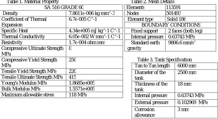
Table 1. Material Property Table 2. Mesh Details Elements 1113591 Nodes 5014501493
Element type Solid 186 BOUNDARY CONDITIONS Fixed support 2 faces (both leg) Internal pressure 0.63743 MPa Standard earth
gravity
9806.6 mm/s2
Table 3. Tank Specification
Material used for fabricating the pressure vessel is SA 516 grade 60 whose Density, Ultimate tensile strength, Young's modulus, Maximum allowable stress, Tensile yield strength etc has been mentioned in table 1. Hexagonal meshing was done in the pressure vessel. Element type selected was Solid 186 with 3 degrees of freedom and 20 nodes. No of elements after meshing is around 1 lakh and nodes are around 5 lakh. The tank designed is of horizontal type with ellipsoidal head and three nozzle are provided and saddle support is given for the pressure vessel. Naphtha is the fluid that is stored in the vessel with density of 665 kg/m3.
SA 516 GRADE 60
Density 7.8611e-006 kg mm^-3 Coefficient of Thermal
Expansion
6.7e-005 C^-1
Specific Heat 4.34e+005 mJ kg^-1 C^-1 Thermal Conductivity 6.05e-002 W mm^-1 C^-1 Resistivity 1.7e-004 ohm mm Compressive Ultimate Strength
MPa
0
Compressive Yield Strength MPa
250
Tensile Yield Strength MPa 220 Tensile Ultimate Strength MPa 415
Young's Modulus MPa 1.8685e+005 Bulk Modulus MPa 1.5571e+005 Maximum allowable stress 118 MPa
Tan to Tan length 6000 mm Diameter of the
tank
2500 mm
Thickness of the tank
18 mm
Internal pressure 0.63743 MPa External pressure 0.102969 MPa Corrosion
allowance
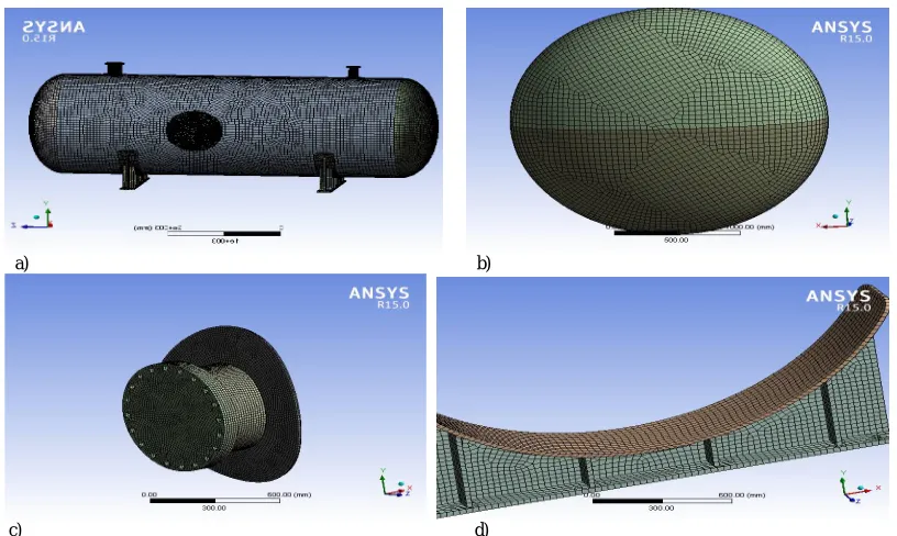
Fig. 1 solid model of Pressure Vessel designed in Catia
Solid model of Pressure Vessel was designed using Catia design software as per the dimension that has been obtained after the design procedure done using ASME Section VIII division 1,2013. This model was imported into ANSYS software for further analysis.
a) b)
c)
d)
Fig. 2 (a)Meshing of Pressure vessel (b) Meshing of Head (c) Meshing of Nozzle (d) Meshing of Support
V.RESULTS
Different cases had been analysed by changing the thickness of the vessel as said earlier and following results had been obtained for different cases
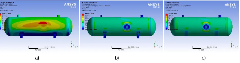
1) Pressure vessel with 18 mm thickness
a) b) c)
Fig. 3 (a)Total Deformation (b) Von-Mises stress (c) Von-Mises stress (without support)
Pressure vessel with 18 mm thickness after analysis it was seen that total deformation was 1.5133 mm and it was maximum near the manhole, also the Von -Mises Stress in the vessel was 86.914 MPa and it was maximum near to the manhole pad. This is because of the stress concentration that occurs in the hole that was created for manhole.
2) Pressure vessel with 16 mm thickness
a) b) c)
Fig. 4 (a) Total Deformation (b) Von-Mises stress (c) Von-Mises stress (without support)
Pressure vessel with 16 mm thickness after analysis it was seen that total deformation was 1.8677 mm and it was maximum near the manhole, also the Von -Mises Stress in the vessel was 112.65 MPa and it was maximum near to the manhole pad. This is because of the stress concentration that occurs in the hole that was created for manhole.
a) b) c)
Fig. 5 (a) Total Deformation (b) Von-Mises stress (c) Von-Mises stress (without support)
Pressure vessel with 16 mm thickness after analysis it was seen that total deformation was 1.8677 mm and it was maximum near the manhole, also the Von -Mises Stress in the vessel was 112.65 MPa and it was maximum near to the manhole pad. The maximum allowable stress is 118 MPa and the value that we obtained is at the verge of that value, so we decided to increase the diameter of the manhole pad to reduce the Von -Mises stress. In this case the Von-Mises Stress was 94.261 MPa. So the pressure vessel is safe.
VI.CONCLUSION
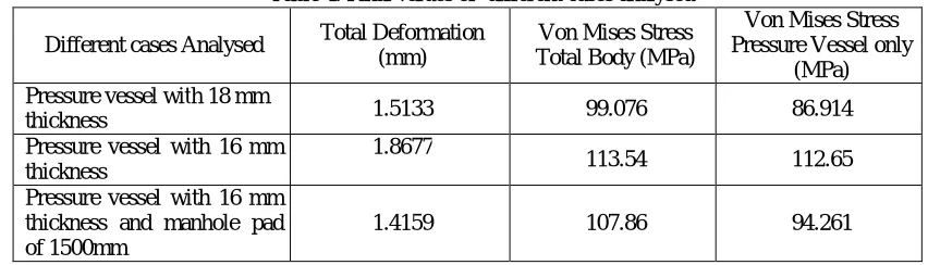
From the table 4 given below it is clear that thickness of vessel can be reduced from 18mm to 16mm ,by increasing the diameter of manhole pad from 996mm to 1500mm. We also observed that mass of the vessel can be reduced from 10138 kg ( pressure vessel with 18 mm thickness and manhole reinforcement pad of diameter 996 mm) to 9319 kg (pressure vessel with 16 mm thickness and manhole reinforcement pad of diameter 1500 mm).So we have been able to reduce the mass of vessel upto 819 kg
Table 4. Final values of different cases analysed
Different cases Analysed Total Deformation (mm)
Von Mises Stress Total Body (MPa)
Von Mises Stress Pressure Vessel only
(MPa) Pressure vessel with 18 mm
thickness 1.5133 99.076 86.914
Pressure vessel with 16 mm thickness
1.8677
113.54 112.65
Pressure vessel with 16 mm thickness and manhole pad of 1500mm
1.4159 107.86 94.261
REFERENCES
[1] Donald M. Fryer, John F. Harvey, High Pressure Vessels, Springer, pp.1-10,1998.
[2] Somnath Chattopadhyay, Overview of pressure vessels, Pressure vessels design and practice, pp.1-14, 2004. [3] Dennis R. Moss, Pressure vessel design manual, Gulf Professional Publishing,ELSEVIER, 3rd ed , pp.14-45, 2004.
[4] Shaik Abdul Lathuef, K.Chandra Sekhar, Design And Structural Analysis Of Pressure Vessel Due To Change Of Nozzle Location And Shell Thickness, IJAERS, Vol. I, Issue II, pp. 218-221, 2012.
[5] M. Pradeep Kumar, K. Vanisree, Design And Implementation Of Circular Cross Sectional Pressure Vessel Using Pro-E And ANSYS, IJMER, Vol. 3, Issue. 4, pp. 2350-2355, 2013.
[6] V.N. Skopinsky, A.B. Smetankin, Modeling And Stress Analysis Of Nozzle Connections In Ellipsoidal Heads Of Pressure Vessels Under External Loading, Int. J. of Applied Mechanics and Engineering, vol. 11, issue. 4, pp. 965-979. 2006.
[7] ASME Section VIII Division 1, The American Society Of Mechanical Engineers, Two Park Avenue, New York, NY, pp. 18-43. 2013