Improving Leaf Area Index Retrieval over
Heterogeneous Surface
S.Anne Priyanka1, R.Raj Mohan2
P.G Scholar, Department of Electronics and Communication Engineering,, Gojan School of Business and Technology, Chennai, Tamil Nadu, India1
Assistant Professor, Department of Electronics and Communication Engineering,, Gojan School of Business and
Technology, Chennai, Tamil Nadu, India2
ABSTRACT: We have been improving leaf area indexretrieval over heterogeneous surface. The collection of ground
measurements for validating remotely sensed crop leaf area index is labor and time intensive. This method presents and automatic measuring system that was designed based on a wireless sensor network (WSN). The data were analyzed in three ways 1) Comparison with LAI-2000, 2) a daily and 5-day aggregated time series analysis, sand 3) a comparison with a Moderate Resolution Imaging Spectro radiometer (MODIS). The preliminary results indicated that the measured LAI values from the LAI Net were correlated with the values derived from LAI-2000. When compared with MODIS LAI, we found that the spatial values of the ground LAI Net observations and the scaled-up ASTER (Advanced Space borne Thermal Emission and Reflection radiometer) LAI were identical or similar to the MODIS LAI values over time. With its low cost and low energy consumption, the proposed WSN observation system is a promising method for collecting ground crop LAI in flexible time and space for validating the remote sensing land products.
KEYWORDS: LAI, Land surface, growth ratio.
I. INTRODUCTION
Interpretation and application of LAI
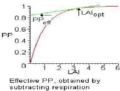
Figure 1LAI is used to predict photosynthetic primary production, transpiration and as a reference tool for crop growth. As such, LAI plays an essential role in theoretical production ecology. An inverse exponential relation between LAI and light interception, which is linearly proportional to the primary production rate, has been established.
Where Pmax designates the maximum primary production and designates a crop-specific growth coefficient.
II. EXISTING METHOD
.
There are two main categories of procedures to estimate LAI: 1) Direct method 2) Indirect methods. The former group consists of methods measuring leaf area in a direct way, while the latter group consists of methods where LAI is derived from more easily (in terms of time, workload, technology) measurable parameters. In this review article, basic inversion theories, demonstrated advantages and disadvantages of the more frequently used direct and indirect techniques to estimate LAI in forests will be discussed.
DIRECT METHOD
Direct methods can be easily applied on deciduous species by collecting leaves during leaf fall in traps of certain area distributed below the canopy. The area of the collected leaves can be measured using a leaf area meter or an image scanner and image analysis software. The measured leaf area can then be divided by the area of the traps to obtain LAI. That way it is not necessary to measure the area of all leaves one by one, but weigh the collected leaves after drying (at 60–80 °C for 48 h). Direct methods in evergreen species are necessarily destructive. However, they are widely used in crops and pastures by harvesting the vegetation and measuring leaf area within a certain ground surface area. It is very difficult (and also unethical) to apply such destructive techniques in natural ecosystems, particularly in forests of evergreen treespecies.Due to the difficulties and the limitations of the direct methods for estimating LAI, they are mostly used as reference for indirect methods that are easier and faster to apply.
(2)Indirect non-contact measurements
Fig.2.Fisheye photography
Due to the subjectivity and labor involved with the first method, indirect non-contact measurements are typically preferred. Non-contact LAI tools, such as hemispherical photography, Hemi-view Plant Canopy Analyser from Delta-T Devices, the CI-110 Plant Canopy Analyzer from CID Bio-Science, LAI-2200 Plant Canopy Analyzer from LI-COR Biosciences and the from Decagon Devices, measure LAI in a non-destructive way. Hemispherical photography methods estimate LAI and other canopy structureattributes from analyzing upward- looking fisheye photographs taken beneath the plant canopy. The LAI-2200 calculates LAI and other canopy structure attributes from solar radiation measurements made with a wide-angle optical sensor. Measurements made above and below the canopy are used to determine canopy light interception at five angles, from which LAI is computed using a model of radiative transfer in vegetative canopies. The LP-80 calculates LAI by means of measuring the difference between light levels above the canopy and at ground level, and factoring in the leaf angle distribution, solar zenith angle, and plant extinction coefficient. Such indirect methods, where LAI is calculated based upon observations of other variables (canopy geometry, light interception, leaf length and width, etc.) are generally faster, amenable to automation, and thereby allow for a larger number of spatial samples to be obtained. For reasons of convenience when compared to the direct (destructive) methods, these tools are becoming more and more important.
Indirect non-contact LAI measurement methods
III. METHODOLOGY
LAINET:
LAINET is an automatic device that obtains multi-angle transmittance of the vegetation canopy during the day following sun’s movement based on WSN technology and then calculates the crop LAI from multi-angle transmittance using a vegetation gap probability model. This WSN consists of three different nodes:
1) Circle node with 3 light sensors. 2) Linear node with 9 light sensors. 3) Sink nodes with GPRS network
The first node type is a circle node with three light sensors that are deployed above the canopy
.The second node type is a linear node with nine light sensors placed under the canopy and that receive the permeated radiation. Sink nodes are used to collect and transmit the data to a remote data server through general packet radio service network.
ADVANTAGES OF LAINET:
1) It can reduce the time required for one to access the experimental site, therefore can minimize the plant disturbances by the experimenter which is not possible with current traditional instruments.
2) Multiple measurement nodes are
automatically synchronised which ensures that the measured data of each node are
obtained simultaneously and avoids the data Uncertainty caused by the differences in measurement time.
3) The field data are remotely transmitted to the data centre via public wireless network and are automatically saved on the data base server.
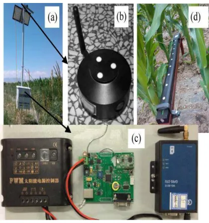
Figure 3LAI Net nodes Figure (a): The solar power system and the sink nodes above the canopy Figure (b): The zoom of a node above the canopy
Figure(c): The zoom of a sink node (middle), the solar power control (left) and GPRS unit (right) Figure (d): The linear nodes with 9 light sensors.
IV. TABULATION
Hardware Cost Labor (Work Days)
Type Single
Deploying Per Total Number Total measurement Maintain
price cost
cycle
LAI2000 $8000 2 $16000 0 4-32 0 32-416
LAINet $250 90 $ 22500 6 0 3 9
INSTRUMENTS VERSUS LAINET From the tabulation:
The traditional measurements take approximately 4-32 days of labour to complete the weekly repeated measurements.
For growth time of 3 months and a sampling frequency of 7 days e.g., approximately 13 times the observation are required to obtain continuous observed data over such a long period of time.
The approximate cost efficiency comparison between LAINET and traditional instruments is given in the tabulation.
V. TECHNOLOGIES
MICROCONTROLLER
The AT89S52 is a low-power, high-performance CMOS 8-bit microcontroller with 8K bytes of in-system programmable Flash memory. The device is manufactured using Atmel’s high-density non-volatile memory technology and is compatible with the industry standard 80C51 instruction set and pin-out. The on-chip Flash allows the program memory to be reprogrammed in-system or by a conventional non- volatile memory programmer. By combining a versatile 8-bit CPU with in-system programmable Flash on a monolithic chip, the Atmel AT89S52 is a powerful microcontroller which provides a highly-flexible and cost-effective solution to many embedded control applications.
Features:
•Compatible with MCS®-51 Products
• 8K Bytes of In-System Programmable (ISP) Flash Memory – Endurance: 10,000 Write/Erase Cycles •4.0V to 5.5V Operating Range
•Fully Static Operation: 0 Hz to 33 MHz
SIM900 GSM/GPRS Module
This GSM Modem can accept any GSM network operator SIM card and act just like a mobile phone with its own unique phone number. Advantage of using this modem will be that you can use its RS232 port to communicate and develop embedded applications. Applications like SMS Control, data transfer, remote control and logging can be developed easily.
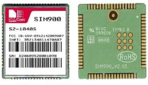
Figure 4 - SIM900 pin diagram
SIM900 is designed with a very powerful single-chip processor integrating AMR926EJ-S core
An embedded Powerful TCP/IP protocol stack
Based upon mature and field-proven platform, backed up by our support service, from definition to design and production.
QUICK START GUIDE
Insert SIM card: Press the yellow pin toremove the tray from the SIM cardholder. After properly fixing the
SIM card in the tray, insert the tray in the slot provided.
Connect Antenna: Screw the RF antenna ifnot already connected.
Connect RS232 Cable to PC/MCU:
(Cable provided for RS232 communication). Default baud rate is 9600 with 8-N-1, no hardware handshaking.
Connect the power Supply (12V 1A) to thepower input of board. Polarity should be Center +ve and outer–ve DC jack.
Network Led indicating various status of GSM module eg. Power on, network registration & GPRS
connectivity.
After the Modem registers the network, led will blink in step of 3 seconds. At this stage you can start using Modem for your application.
AT commands can be sent to control GSM Modem.
For sending SMS in text Mode:
AT+CMGF=1 press enter
Once The AT commands is given’ >’ prompt will be displayed on the screen. Type the message to send via SMS. After this, press
“ctrl+Z” to send the SMS.
If the SMS sending is successful, “ok” will be displayed along with the message number.
For reading SMS in the text mode:
AT+CMGF=1 Press enter
AT+CMGR= no.
Number (no.) is the message index number stored in the SIM card. For new SMS, URC will be received on the screen as +CMTI: SM
‘no’. Use this number in the AT+CMGR number to read the message.
GUIDE TO VOICE CALLING
Initiating outgoing call:
ATD+ mobile number; <enter key>
For disconnecting the active call:
ATH <enter key>
For receiving incoming call:
ATA <enter key>
Note: The modem automatically sets to the baud rateof the first command sent by the host system after it is powered up. So there is no need for setting the baud rate using commands. Before you start using the modem, please make sure that the SIM card you inserted support the needed features and there is enough balance in SIM
RF TRANSCEIVER
The QFMT5 and QFMR5 data link modules are miniature UHF radio modules, which enable the implementation of a simple telemetry link up to 300 meters, and at data rates of up to 128Kbit/s The QFMT5 and QFMR5 modules will suit one-to one and multi-node wireless links in applications including building and car security, remote industrial process monitoring and computer networking. Because of its small size and low power requirements, these modules are ideal for use in portable battery powered wireless applications.
change their electrical properties in some way such as Photo-resistors or Photo-conductors.
Photo-junction Devices – These photo-devices are mainly true semiconductor devices such as the photodiode or phototransistor which use light to control the flow of electrons and holes across their PN-junction. Photo-junction devices are specifically designed for detector application and light penetration with their spectral response tuned the wavelength of incident light.
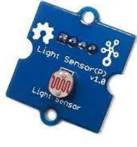
Figure 5- light sensor
VI. HARDWARE AND SOFTWARE
IMPLEMENTATION
MICROCONTROLLER 40 PIN IC 89S52
RF TRANCEIVER
PIR SENSOR
LDR
LCD DISPLAY
GSM
MPLAB IDE COMPILER
EMBEDDED C LANGUAGE
VII. IMPLEMENTATION
inclination angles, k is well approximated by 0.50. Extinction coefficients reported for 13 needle and broad-leaved tree species ranged from 0.28 to 0.65 and averaged 0.47.
VIII. CONCLUSION
In this present work, system has been designed and interfaced using a microcontroller with upper and lower Light sensors, PIR sensors RF transceiver, GSM module and test that for result by using Beer-Lambert Law. The light below the canopy, Qi, is related to the light above the canopy, Q0, and LAI, by the relationship Qi=Qoe^-KLAI and solving for LAI gives LAI = - ln (Qi / Qo)/ k.
REFERENCES
[1] G. B. Bonan, “Land–atmosphere interactions for climate system models: Coupling biophysical, biogeochemical, ecosystem dynamical processes,” Remote Sens. Environ., vol. 51, no. 1, pp. 57–73, Jan. 1995.
[2] P. J. Sellers et al., “Modeling the exchanges of energy, water, carbon between continents and the atmosphere,” Science, vol. 275, no. 5299, pp. 502– 509, Jan. 1997.
[3] R. B. Myneni et al., “Global products of vegetation leaf area and fraction absorbed PAR from year one of N MODIS data,” Remote Sens. Environ., vol. 83, no. 1/2, pp. 214–231, Nov. 2002.
[4] F. Deng, J. M. Chen, S. Plummer, M. Z. Chen, and . Pisek, “Algorithm for global leaf area index retrieval using satellite imagery,” IEEE Trans. Geosci. Remote Sens., vol. 44, no. 8, pp. 2219–2229, Aug. 2006.