IJEDR1603048
International Journal of Engineering Development and Research (www.ijedr.org)297
Mitigation Of Sag And Swell In Multibus System By
Using DPFC
1
T.Naga Bhargavi,
2B.Vijaya Krishna,
3G.Anil kumar
1Student, 2Assistant Professor,3Assistant professor 1Department Of Electrical & Electronics Engineering
1Bapatla Engineering College, Bapatla, India
________________________________________________________________________________________________________
Abstract -present days the demand of electricity and nonlinear loads increases, power quality problems will be occurs in the interconnected power system network. Power quality problems are voltage sag and swell can be eliminated by using distributed power flow controller then power quality can be improved. The switching level model is constructed using three phase six pulse shunt converter and single phase four pulse series converters. Both the converters are modeled as back to back voltage source inverters connected without the D.C link are controlled by pulse width modulation scheme. This model is implemented to the bus system of 2,3,5 bus system at different loads . The detailed DPFC simulation in switching level model is performed in Matlab/Simulink environment
IndexTerms – Distributed power flow controller(DPFC), ,Voltage sag, Voltage swell, Custom Power, Power quality ________________________________________________________________________________________________________
I.INTRODUCTION
In recent years, power quality disturbances become most issue which makes many researchers interested to find the best solutions to solve it. Power quality in the power system is the important issue for industrial, commercial and residential applications today. The voltage problem is mainly considered from under-voltage (voltage sag) condition over current caused by short circuit or fault somewhere in the system. In customer opinion a power problem is deviation in voltage, current and frequency that results in failure.To overcome the voltage sag and swell problems fast acting power electronics based FACTS (flexible A.C transmission system) devices are introduced. The flexible ac-transmission system(FACTS) that is defined by IEEE as “a power-electronic base system and other static equipment that provide control of one or more ac-transmission system parameters to enhance controllability and increase power-transfer capability” and can be Utilized for power-flow control. Currently, the distributed power-flow controller (DPFC) .This paper introduces a new concept, called distributed power-flow controller (DPFC) that is derived from the UPFC. The same as the UPFC, the DPFC is able to control. all system parameters. The DPFC eliminates the common dc link between the shunt and series converters. The active power exchange between the shunt and the series converter is through the transmission line at the third-harmonic frequency. The series converter of the DPFC employs the distributed FACTS (D-FACTS) concept Comparing with the UPFC, the DPFC have two major advantages: 1) low cost because of the low-voltage isolation and the low component rating of the series converter and 2) high reliability because of the redundancy of the series converters. This paper begins with presenting the principle of the DPFC, followed by its modeling. After a short introduction of the types of buses, the paper ends with the experimental results of the DPFC applied to the 2,3,5 bus system applying load between any two buses. In this paper, a distributed power flow controller, introduced as a new FACTS device, is used to mitigate voltage and current waveform deviation and improve power quality in a matter of seconds. The DPFC structure is derived from the UPFC structure that is included one shunt converter and several small independent series converters. The DPFC has capability to balance the line parameters, i.e., line impedance, transmission angle, and bus voltage magnitude. After implementing the DPFC between the buses in bus systems sag and swell in voltage and current are mitigated and the real and reactive powers are improved so the power quality increases in the system was verified through simulations with MATLAB/Simulink software
II.DISTRIBUTED POWER FLOW CONTROLLER
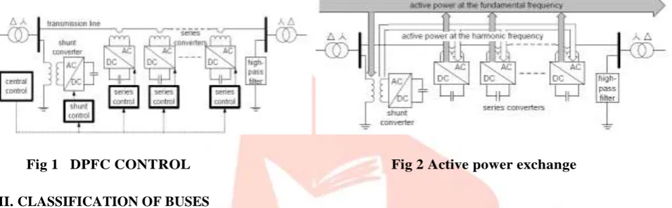
The modeling of the DPFC consists of the converter modeling and the network modeling. Due to the use of single-phase series converters, they are modeled as a single-phase system. To ensure that the single-phase series converter model is compatible with the three-phase network model, the network is modeled as three single-phase networks with 120◦ phase shift. the flow chart of the DPFC modeling process, which leads to six separated models Within the DPFC, the transmission line presents a common connection between the AC ports of the shunt and the series converters. Therefore, it is possible to exchange active power through the AC ports. The method is based on power theory of non-sinusoidal components. According to the Fourier analysis, non-sinusoidal voltage and current can be expressed as the sum of sinusoidal functions in different frequencies with different amplitudes. DPFC is controlled by the three schemes of controlling
IJEDR1603048
International Journal of Engineering Development and Research (www.ijedr.org)298
The central control generates the reference signals for both the shunt and series converters of the DPFC. Its control function depends on the specifics of the DPFC application at the power system level, such as power flow control, low frequency power oscillation damping and balancing of asymmetrical components. According to the systemrequirements, the central control gives corresponding voltage reference signals for the series converters and reactive current signal for the shunt converter. All the reference signals generated by the central control concern the fundamental frequency components. Each series converter has its own series control. The controller is used to maintain the capacitor DC voltage of its own converter, by using 3rd harmonic frequency components, in addition to generating series voltage at the fundamental frequency as required by the central control. The controller inputs are series capacitor voltages, line current, and series voltage reference in the dq frame. The third-harmonic frequency control is the major control loop with the DPFC series converter control. The principle of the vector control is used here for the dc-voltage control. The third-harmonic current through the line is selected as the rotation reference frame for the single-phase park transformation, because it is easy to be captured by the phase-locked loop(PLL) in the series converter. The objective of the shunt control is to inject a constant 3rd harmonic current into the line to supply active power for the series converters. At the same time, it maintains the capacitor DC voltage of the shunt converter at a constant value by absorbing active power from the grid at the fundamental frequency and injecting the required reactive current at the fundamental frequency into the grid.
Fig 1 DPFC CONTROL Fig 2 Active power exchange
III. CLASSIFICATION OF BUSES
Load Buses : In these buses no generators are connected and hence the generated real power PGiand reactive power QGi are taken as zero. The load drawn by these buses are defined by real power -PLi and reactive power -QLi in which the negative sign accommodates for the power flowing out of the bus. This is why these buses are sometimes referred to as P-Q bus. The objective of the load flow is to find the bus voltage magnitude |Vi| and its angle.
Voltage Controlled Buses : These are the buses where generators are connected. Therefore the power generation in such buses is controlled through a prime mover while the terminal voltage is controlled through the generator excitation. Keeping the input power constant through turbine-governor control and keeping the bus voltage constant using automatic voltage regulator, we can specify constant PGi and | Vi | for these buses. This is why such buses are also referred to as P-V buses. It is to be noted that the reactive power supplied by the generator QGi depends on the system configuration and cannot be specified in advance.
Furthermore we have to find the unknown angle δi of the bus voltage.
Slack or Swing Bus : Usually this bus is numbered 1 for the load flow studies. This bus sets the angular reference for all the other buses. Since it is the angle difference between two voltage sources that dictates the real and reactive power flow between them, the particular angle of the slack bus is not important. However it sets the reference against which angles of all the other bus voltages are measured. For this reason the angle of this bus is usually chosen as 0° . Furthermore it is assumed that the magnitude of the voltage of this bus is known
IV. BUS SYSTEMS
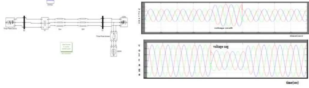
a)BUS SYSTEMS WITHOUT DPFC
IJEDR1603048
International Journal of Engineering Development and Research (www.ijedr.org)299
Fig 3 Two bus system without DPFC Fig 4 Two bus system voltage sag and swell without DPFC at 0.08-0.12secFig 5 Three bus system without DPFC
IJEDR1603048
International Journal of Engineering Development and Research (www.ijedr.org)300
Fig 7 Real and Reactive power at bus 2 and bus3 in Three bus system without dpfc at sag 0.04 to0.08sec
Fig 8 Voltage and current swell at bus 2 and 3 bus in three bus system without dpfc at 0.04 to 0.08sec
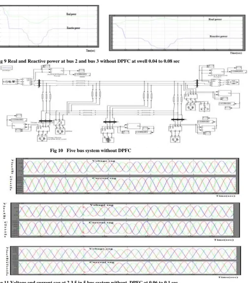
Fig 9 Real and Reactive power at bus 2 and bus 3 without DPFC at swell 0.04 to 0.08 sec
Fig 10 Five bus system without DPFC
IJEDR1603048
International Journal of Engineering Development and Research (www.ijedr.org)301
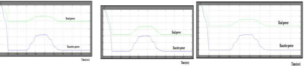
Fig 12.Real and Reactive powers at 2,3,5 in 5 bus system without DPFC at sag 0.06to0.1sec
Fig 13.Voltage and current swell at 2,3,5 buses in 5 bu system without DPFC at 0.06 to 0.1sec
Fig 14 Real and reactive powers at 2,3,5 bus in 5 bus system without DPFC
b) BUS SYSTEMS WITH DPFC
IJEDR1603048
International Journal of Engineering Development and Research (www.ijedr.org)302
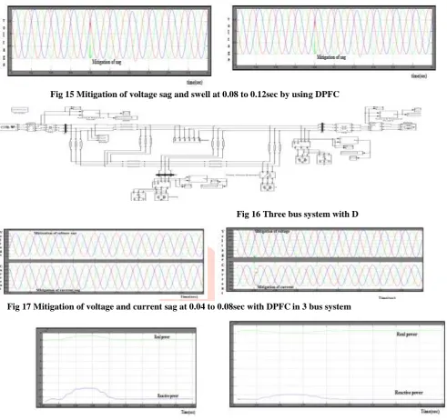
Fig 15 Mitigation of voltage sag and swell at 0.08 to 0.12sec by using DPFCFig 16 Three bus system with D
Fig 17 Mitigation of voltage and current sag at 0.04 to 0.08sec with DPFC in 3 bus system
Fig 18 Real and reactive power after mitigate the sag at 2,3 buses in 3 bus system with DPF
Fig 18 Mitigation of voltage and current swell at 2,3 buses in 3 bus system with dpfc
IJEDR1603048
International Journal of Engineering Development and Research (www.ijedr.org)303
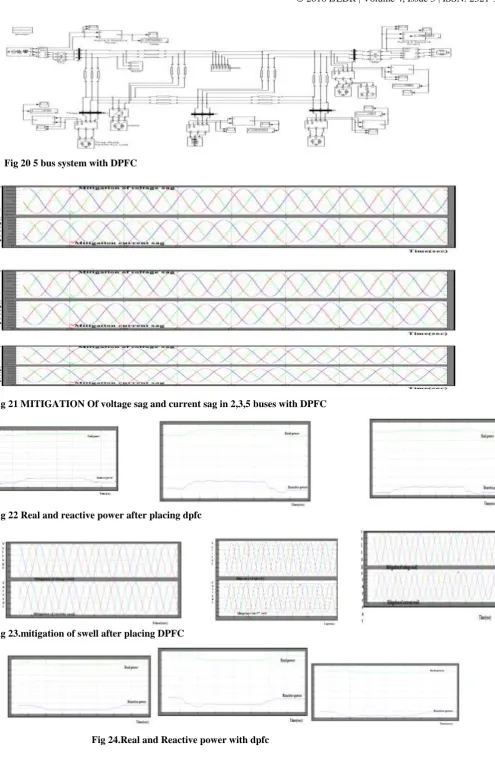
Fig 20 5 bus system with DPFC
Fig 21 MITIGATION Of voltage sag and current sag in 2,3,5 buses with DPFC
Fig 22 Real and reactive power after placing dpfc
Fig 23.mitigation of swell after placing DPFC
IJEDR1603048
International Journal of Engineering Development and Research (www.ijedr.org)304
V.CONCLUSIONThe reliability of the DPFC is greatly increased because of the redundancy of the series converters. The total cost of the DPFC is also much lower than the UPFC, because no high-voltage isolation is required at the series-converter part and the rating of the components of is low.Mainly, in this we are applying this DPFC to the multibus system of 2-bus,3-bus,and 5-bus system when the sudden load is applied to the system and sudden load is eliminated through the circuit breaker of different timings for the different buses tthe sag and swell are in these systems we mitigate these sag and swell which improves power quality using DPFC system in simulink is verified
REFERENCES
[1] Y.-H. Song and A. Johns, Flexible ac Transmission Systems (FACTS) (IEE Power and Energy Series), vol. 30. London, U.K.: Institution of Electrical Engineers, 1999.
[2] N. G. Hingorani and L. Gyugyi, Understanding FACTS : Concepts and Technology of Flexible AC Transmission Systems. New York: IEEE Press, 2000.
[3] L.Gyugyi, C.D. Schauder, S. L.Williams, T. R. Rietman,D. R. Torgerson,andA. Edris, “The unified power flow controller: Anew approach to power transmission control,” IEEE Trans. Power Del., vol. 10, no. 2, pp. 1085–1097, Apr. 1995.
[4] A.-A. Edris, “Proposed terms and definitions for flexible ac transmission system (facts),” IEEE Trans. Power Del., vol. 12, no. 4, pp. 1848–1853,Oct. 1997.
[5] K. K. Sen, “Sssc-static synchronous series compensator: Theory, modeling, and application,” IEEE Trans. Power Del., vol. 13, no. 1, pp. 241–246,Jan. 1998.