Kalina-Flash Cycle Performance Analysis and Parametric Optimization
Raveendra Nath R1*, C. Vijaya Bhaskar Reddy2, K.Hemachandra Reddy3
,
1 Department of Mechanical Engineering, JNTUA, Ananthapuramu, 515002, India 2 Department of Mechanical Engineering, SVCET, Murakambattu, 517127, India 3 Department of Mechanical Engineering, JNTUA, Ananthapuramu, 515002, India
ABSTRACT
In this paper, a thermodynamic investigation is done on a Kalina-flash cycle. This work is initially validated with the Kalina cycle power plant, Wich is commissioned in Husavic. Low-temperature Kalina-flash is considered for this study. This cycle is working with the ammonia-water mixture. The Kalina-flash cycle was optimized in the view of exergy and thermal efficiency. A multi-objective genetic algorithm is used to accomplish optimization. The optimum values of the objective functions are observed to be 40.20 and 11.70% respectively. At last, The influence of the separator inlet dryness fraction, basic ammonia mass fraction, temperature and flash pressure ratio on the first and second law efficiencies are analysed.
Keywords: genetic algorithm, Kalina cycle, energy efficiency, Exergy efficiency
1 INTRODUCTION
Energy demand is growing day by day. Most of the industries are consuming fossil fuels as energy sources. Rapid fossil fuel resources depletion is causing environmental degradation. The low-grade heat is exhausted to the atmosphere as waste. This energy can produce additional output at the same consumption of fuel and emission of pollutants. Binary mixture cycles of ammonia and water as a working medium had a high potential for power generation in the low-temperature range [1]. In 1984, Kalina introduced the Ammonia-water power cycle for low-temper heat. DiPippo R. [2] has compared the Kalina cycle and Organic Rankine cycle, the results showed that the Kalina cycle is having a better second law efficiency. P.k.nag[7] had reported increment in turbine inlet temperature and separator temperature increase the cycle efficiency, the ammonia concentration has optimum value for every set of key parameters. Wang et al. [3] ran a comparison for Kalina cycle, Organic Rankine cycle, single-flash and dual-pressure steam cycles with cement plant waste heat. As per the optimum results Kalina cycle attains higher Exergy efficiency. Nasruddin et al. [4] have Optimized the Kalina cycle with a geothermal heat source. Energy
and Exergy studied with a variable basic solution concentration. The maximum efficiency and power output had achieved at 78%. Saffari et al. [5] enhanced the geoThermal Kalina cycle with an artificial bee colony algorithm. The observed optimum results for Exergy and Thermal efficiencies are 48.18 % and 20.36 %, respectively. Shokati et al. [6] Examined the exergo-economic performance of an Organic Rankine cycle, dual-pressure, dual-fluid organic Rankine cycle by specific Exergy costing method, the optimum results represented the Kalina cycle can achieve less cost for power generation. Arslan[10] enhanced the KCS-34 cycle performance, an artificial neural network and life cycle cost analysis are studied. The optimum profitable range of ammonia-mass fraction is 80% to 90 %. Ho et al. [11] presented organic flash cycle (OFC), which is like a Kalina cycle, in the OFC binary mixture is heated up to the saturated condition only, thereafter binary mixture is flashed to produce saturated vapour and liquid, They proposed diverse upgrades to organic flash cycle, they described 10% improvement in utilization
efficiency, when compared with optimized basic Organic Rankine cycle with two-stage expansion process and blending the liquid from the flash evaporation in secondary expansion stage. Wang et al.[8] optimized a flash-binary geothermal power generation system with a genetic algorithm. the organic rankine cycle bottoming cycle is Kalina cycle. G.v.Pradeep Varma and T.Srinivas.[12] have compared Kalina cycle, Organic Rankine cycle and dual-flash Organic Rankine cycles. R124 fluid is used for these low-temperature heat cycles. Dual -flash organic rankine cycle had more potential in power generation. Liyancao et al. [13] had examined the Kalina flash cycle for optimum condition. Optimization described higher Exergy efficiency than the Kalina cycle with proposed configurations. It is implemented for Exergy and economic improvement. Thermal efficiency is determined, but not considered for Multi-Objective Optimization.
2. SYSTEM DESCRIPTION
fig.1 .schematic diagram of Kalina cycle 3. mathematical model and performance criteria
All the components in Kalina-flash cycle can be treated as control volume. The Kalina-flash cycle is designed on mass and energy conservation principle. Some assumptions were made as follows to simplify the mathematical model.
1. The cycle is in a steady state. Potential and kinetic energies are not considered. 2. All over the system, pressure and heat losses are ignored.
3. The isentropic efficiency of the expander and pumps were treated as fixed constants. 4. The working fluid from the separator is treated as saturated gas and liquid.
5. The working fluid at the exit of the condenser is considered as the saturated liquid. 6. Throttling is the isenthalpic process.
The mathematical expressions for the components of the proposed system as per the mentioned assumptions is as follows.
In HSRVG energy balance is expressed as mg(hg1-hg2)=m1(h1-h20) (1)
The heat addition from the heat source in the HRSG is given by Qin=Mg(hg1-hg2) (2)
For the turbine, an isentropic process is deviated, which is expressed as efficiency as follows.
ηturbine=
ℎ3−ℎ5
ℎ3−ℎ5𝑠 (3)
Wtb=m3(h3-h5) (4)
The law of mass conversation of the separator is described as Min=moutl+moutg (5)
Minxin=moutlxoutl+moutgxoutg (6)
In a heat exchanger, the energy balance is given by Mwf(hin,wf-hout,wf)=mcw(hout,cw-hin,cw) (7)
the pump, isentropic efficiency expressed as
ηpump =
ℎ1𝑠−ℎ14
ℎ1−ℎ14 (8)
The power input to the pump is given by Wp =Mbs(h1-h20) (9)
For the throttling valve, an isenthalpic process is expressed as hin=hout (10)
Wnet=wtb-wp1-wp2 (11)
Thermal efficiency is defined as ηThermal=
𝑤𝑛𝑒𝑡
𝑄𝑖𝑛 (12)
Exergy efficiency is described as ηExergy=
𝑤𝑛𝑒𝑡
𝐸𝑖𝑛 (13)
3.2 mathematical model validation
The available literature is used to validate the mathematical simulation. The kalian cycle is validated with the Ref. (14). The relative error between our model and reference literature is less than 2%. The thermodynamic properties of the ammonia-water are calculated with REFPROP 9.1 and Matlab software.
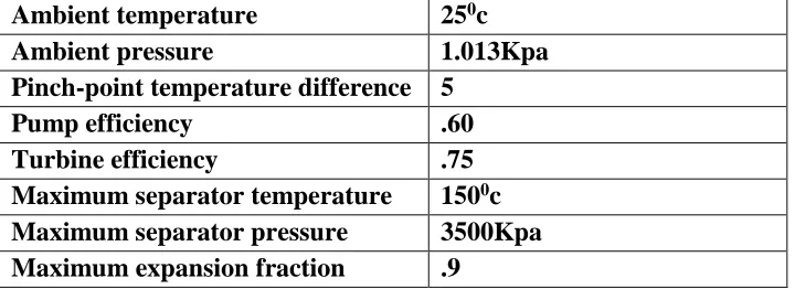
Table 1
The simulation and boundary conditions
Term
Value
Heat source
Ethylene glycol
temperature of heat source
170
0c
Ambient temperature
25
0c
Ambient pressure
1.013Kpa
Pinch-point temperature difference 5
Pump efficiency
.60
Turbine efficiency
.75
Maximum separator temperature
150
0c
Maximum separator pressure
3500Kpa
Maximum expansion fraction
.9
Table 2
The optimization parameters
Term
Limits
Optimum Values
Population size
100
100
Generations
100
100
Separator Dryness fraction limits
0.2 - 0.9
0.61
Separator temperature limits
80
0c - 150
0c
387.03
Basic solution Concentration
0.2 - 0.9
0.85
Flash pressure ratio
0.2 - 0.9
0.81
Table 3
System parameters at optimum condition
1 387.03 41.32 0.85 1300.12 25.00 0.61
2 387.03 41.32 0.98 1770.28 15.32 1.00
3 387.03 41.32 0.63 555.38 9.68 0.00
4 317.65 9.55 0.98 1615.96 15.32 0.95
5 377.62 33.47 0.63 555.38 9.68 0.05
6 377.62 33.47 0.98 1767.98 0.49 1.00
7 377.62 33.47 0.62 490.11 9.18 0.00
8 318.50 9.55 0.98 1634.24 0.49 0.96
9 334.23 33.47 0.62 262.80 9.18 0.00
10 332.64 9.55 0.62 490.11 9.18 0.19
11 328.40 9.55 0.85 1202.87 25.00 0.66
12 321.14 9.55 0.85 1102.53 25.00 0.60
13 303.00 9.55 0.85 309.04 25.00 0.00
14 303.35 41.32 0.85 312.59 25.00 0.00
15 323.39 41.32 0.85 412.93 25.00 0.00
16 339.78 41.32 0.85 496.41 25.00 0.00
q
h(kj)
fig.2 effect of dryness fraction on Thermal efficiency, Exergy efficiency, work output, work ratio.
fig.4 effect of flash pressure ratio on Thermal efficiency, Exergy efficiency, work output, work ratio.
4.Result and discussion
In this section, a Kalina-flash power cycle parametric analysis is done with a low-temperature heat source. optimization is also conducted to investigate the optimum thermodynamic performance of Kalina-flash power cycle. The boundary conditions and simulation parameters are summarized in Table .1. restricted conditions of an expander are shown in Table.2.
4.1. Parametric analysis at optimum condition.
A parametric analysis is conducted for the Kalina-flash cycle to examine the effect of four key parameters on the cycle performance. Three parameters include expander inlet quality (q2), the
concentration of the basic solution (xb), and flash expansion ratio, with relative to expander inlet
temperature (t2)are studied. Each parameter influence is studied along with separator temperature, while
other parameters are kept constant as listed in Table.3
turbine, which leads to a drop in the mass flow rate to the flash turbine. Flash turbine work output relative to the first turbine work output is falling.
Fig.3 shows the effect of the ammonia-water basic solution concentration on Exergy efficiency, Thermal efficiency, net power output, and work ratio. At the constant temperature, as the concentration of
ammonia-water increases, the turbine inlet pressure is falling, the mass flow rate to the separator is increasing. The net power output is mainly depended on the ammonia-rich vapour. Therefore, the net power output increases with the concentration of an ammonia-water basic solution. Similarly, the saturated vapour generation has also increased in the flash chamber. As a result, the network output and work ratio are increasing, the net power output is the dominant factor in energy efficiency and Exergy efficiency. Therefore, the Exergy efficiency and energy efficiency increase with the concentration of an ammonia-water basic solution. However, concentration rise influences the enthalpy drop in the turbine. As a result work output, work ratio, energy efficiency, and Exergy efficiency are increased. The
temperature and concentration will influence the mass flow rate in both turbines, it leads to improvement in work output, work ratio, energy efficiency, and Exergy efficiency.
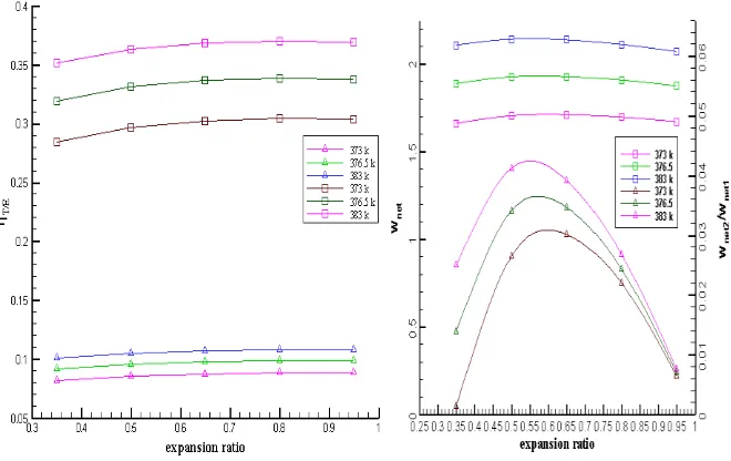
Fig.4 displays the effect of flash pressure ratio on Exergy efficiency, Thermal efficiency, net power output, and work ratio. The flash pressure ratio increases, the mass flow rate of saturated vapour in the second separator is increasing, similarly, enthalpy drop in the second turbine decreasing due to low pressure. The combined effect of these two factors work output increase initially and falls after that. It has little influence on network output. But the work ratio will follow up a positive trend at little pressure ratio and trend reverse after reaching peak value. The influence on overall energy efficiency and Exergy efficiency is also small. The temperature will influence the peak value.