ISSN (Print) : 2320 – 3765 ISSN (Online): 2278 – 8875
I
nternational
J
ournal of
A
dvanced
R
esearch in
E
lectrical,
E
lectronics and
I
nstrumentation
E
ngineering
(A High Impact Factor, Monthly, Peer Reviewed Journal)
Website: www.ijareeie.com
Vol. 6, Issue 10, October 2017
Z-Source Inverter fed Three Phase Induction
Motor drive with PI and PID Controlled
closed loop systems
R.Kapil, Dr.Vijayaragavan
PG Scholar, Dept. of EEE, Bharath University, Chennai, India
Asst. Professor, Dept. of EEE, Bharath University, Chennai, India
ABSTRACT: This paper presents the closed loop control of Z-Source Inverter fed three phase induction motor with PI and PID controller. PI and PID controller systems are designed and simulated using MATLAB. The principle of operation and simulation results is discussed. The simulation results of PI and PID controller are compared interms of time domain parameters and comparison table have been presented.
KEYWORDS: ZSI- Z-Source Inverter, VSI-Voltage Source Inverter Z-Source Inverter fed Induction Motor.
I. INTRODUCTION
The energy demand is increasing worldwide day-by-day. The non-renewable energy sources such as coal,oil and natural gases cannot be replenished once the deposit of these fuels are depleted. So the needs for renewable energy sources are increasing across the world. Among all the renewable energy sources solar energy is expected to play on important role in future energy production [1]-[5]. The PV cells convert solar energy into electrical energy. The PV systems can be grouped into standalone systems and grid connected systems. The PV system generates low voltage and requires high step-up converters for its applications.The DC-DC converter step-up the PV voltage and VSI is used to convert DC voltage to AC voltage [6].
ISSN (Print) : 2320 – 3765 ISSN (Online): 2278 – 8875
I
nternational
J
ournal of
A
dvanced
R
esearch in
E
lectrical,
E
lectronics and
I
nstrumentation
E
ngineering
(A High Impact Factor, Monthly, Peer Reviewed Journal)
Website: www.ijareeie.com
Vol. 6, Issue 10, October 2017
speed drives (ASD) was proposed in [16 ] which provides ride-through capability .Z.J. Zhou et al proposed a new topology of uninterruptable power supply (UPS) using Z-source inverter , maintain the desired AC voltage with high efficiency ,low harmonics , fast response and good steady state performance[17]. Transient modeling and analysis of PWM ZSI was presented by P.C.Loh et al [18]. AC small signal modeling and analysis of ZSI in continuous conduction mode presented in [19].New family of Embedded Z-source inverter (EZSI) was proposed in [20] to maintain smooth voltage or current across the DC source without addition of LC filter. Other topologies of Asymmetric and Symmetric Embedded Z-source inverter were presented in [21]. Current mode integrated control technique for ZSI fed induction motor drives was presented in [22 ] by S.Thangaprakash et.al. Embedded switched-inductor Z-source inverters are presented in [23 ] which provide a high boost voltage inversion ability , lower voltage across the switching devices, continuous input current and a reduced voltage stress on the capacitors. The PI controller and fuzzy logic controller (FLC) are designed and implemented for H6 single phase inverter in [24].But the above literature survey does not deal with closed loop control for EZSIIM. This paper proposes closed loop control for EZSIIM using PI controller and PID controller. PI controller and PID controller circuit are designed and simulated using MATLAB/Simulink and the obtained results are compared.
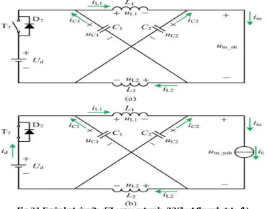
II. OPERATION PRINCIPLES OF Z-SOURCE INVERTER
Fig. 2.1&2.2 shows the equivalent circuits of Z-source network in shoot-through states and non-shoot-through states. The output voltage and output current of Z-source network, respectively, and the reference directions of voltages and currents are all shown in Fig. 2.1. Due to the symmetrical Z-source network, the voltages and currents of each
ISSN (Print) : 2320 – 3765 ISSN (Online): 2278 – 8875
I
nternational
J
ournal of
A
dvanced
R
esearch in
E
lectrical,
E
lectronics and
I
nstrumentation
E
ngineering
(A High Impact Factor, Monthly, Peer Reviewed Journal)
Website: www.ijareeie.com
Vol. 6, Issue 10, October 2017
Active state: The inverter is operated in one of its six active states. The diode D is forward biased. The load and the Inverter Bridge are replaced by the current source as shown in Fig.2.1&2.2.
(The switches Sx ≠ Sx’, x = A, B, or C; D = ON. For time interval T1)
(1)
(2)
Nonshoot-Through zero state: Inverter Bridge is operating in any one of its two nonshoot-through zero states. The
bridge can be viewed as a open circuit. The input DC voltage appears across the inductor and capacitor. But no inverter
output current flows to the load.
During nonshoot-through zero state the switches Sx ≠ Sx’, x = A, B, or C; D = ON.
(3)
(4)
Shoot-through zero state: Shoot through zero state is possible by seven different ways. Without disturbing the active
states, shoot-through state is allocated into each phase within total zero time. The front-end diode D is reverse biased.
The inverter is viewed as a short circuit from its DC link. There is no voltage across the load but the capacitor voltage
is boosted based on the shoot through duty ratio.
(The switches Sx = Sx’ = ON, x = A, B, or C; D = OFF. For time interval (T0)
(5)
(6)
The DC link voltage and peak AC voltage can be expressed by performing the state space averaging results in
(7)
The EZSI provides same voltage gain as that of ZSI with inherent filtering capacity. Embedded sources help to maintain required voltage level within impedance network with lower voltage across the capacitor [11].
ISSN (Print) : 2320 – 3765 ISSN (Online): 2278 – 8875
I
nternational
J
ournal of
A
dvanced
R
esearch in
E
lectrical,
E
lectronics and
I
nstrumentation
E
ngineering
(A High Impact Factor, Monthly, Peer Reviewed Journal)
Website: www.ijareeie.com
Vol. 6, Issue 10, October 2017 III. SIMULATION RESULTS
The simulation circuit for closed loop control with PI and PID controller is designed and simulated using MATLAB/Simulink.
3.1 Z-Source inverter fed induction motor drive closed loop system with PI controller
The simulation circuit of ZSI fed three phase induction motor with PI controller is shown in Fig.3.0.The speed of the induction motor is measured continuously and compared with the reference set speed .The difference in speeds is applied as error signal to the PI controller. The output of PI controller is given to ZSI system to run the induction motor at required speed. The speed of the induction motor with PI controller closed loop is shown in Fig.3.2. And its value is 1248 RPM. The torque of the motor is 1.2 N-m shown in Fig.6.
Fig.3.0. Z-Source Inverter fed three phase induction motor closed loop system with PI controller
ISSN (Print) : 2320 – 3765 ISSN (Online): 2278 – 8875
I
nternational
J
ournal of
A
dvanced
R
esearch in
E
lectrical,
E
lectronics and
I
nstrumentation
E
ngineering
(A High Impact Factor, Monthly, Peer Reviewed Journal)
Website: www.ijareeie.com
Vol. 6, Issue 10, October 2017
Fig.3.2. Speed of the Three phase induction motor with PI controller
Fig.3.3. Torque of the Three phase induction motor with PI controller
3.2 Z-Source inverter fed induction motor drive closed loop system with PID controller
The simulation circuit of ZSI fed three phase induction motor with PID controller closed loop is shown in Fig.3.4.The difference in set speed and actual speed is given as error signal to PID controller. The output signal of the controller is applied to ZSI to obtain the required speed. The speed of the motor is 1248 RPM and is shown in Fig.3.6. The torque response of the system is shown in Fig3.7. And its value is 1.2 N-m.
ISSN (Print) : 2320 – 3765 ISSN (Online): 2278 – 8875
I
nternational
J
ournal of
A
dvanced
R
esearch in
E
lectrical,
E
lectronics and
I
nstrumentation
E
ngineering
(A High Impact Factor, Monthly, Peer Reviewed Journal)
Website: www.ijareeie.com
Vol. 6, Issue 10, October 2017
Fig.3.5. Input voltage
Fig.3.6. Speed of the Three phase induction motor with PID controller
Fig.3.7. Torque of the Three phase induction motor with PI controller
The summary of the time domain parameters of Z-Source Induction motor drive closed loop system with PI controller and PID controller are given in table.1.
Table-1
Comparison of time domain parameters for PI and PID controller closed loop system Controller Rise time (s) Peak time (s) Setting time (s) Steady state error
(RPM)
PI 2.6 2.7 3.2 5.6
PID 2.5 2.6 2.7 3.2
ISSN (Print) : 2320 – 3765 ISSN (Online): 2278 – 8875
I
nternational
J
ournal of
A
dvanced
R
esearch in
E
lectrical,
E
lectronics and
I
nstrumentation
E
ngineering
(A High Impact Factor, Monthly, Peer Reviewed Journal)
Website: www.ijareeie.com
Vol. 6, Issue 10, October 2017 IV. CONCLUSION
The closed loop control of ZSI fed three phase induction motor with PI controller and PID controller are simulated successfully. I t is observed from the simulation results that PID controlled closed loop system provides better results than PI controller, since PID controlled system reduces rise time , settling time of the closed loop system and the steady state error in speed is reduced to 3.2 RPM. Contribution of this work is to obtain the better dynamic response of the ZSIIM closed loop system. The fuzzy logic based closed loop system will be simulated in future.
REFERENCES
[1] D.J. Arent, A.Wisel, and R.Gelman, “The status and prospects of renewable energy for combating global warming,” Elseiver Energy Economics, Vol. 33, No. 4, pp.584-593, Jul. 2011.
[2] F.Blaabjerg, Z. Chen, and S.B.Kjaer, “Power electronics as efficient interface in dispersed power generation systems,” IEEE Trans.Power Electron, Vol. 19, No. 5, pp. 1184-1194, Sep.2014.
[3] L.Zhang , K. Sun, Y. Xing , and M. Xing, “H6 Transformerless full -bridge PV grid-tied inverters,” IEEE Trans.Power Electron, Vol. 29, No.3, pp. 1229-1238,Mar.2014.
[4] Rong-Jong Wai and Wen-Hung Wang , “Grid-connected photovoltaic generation systems,” IEEE Trans. Circuits and systems ., Vol.55. No.3. Apr. 2008.
[5] J.A. Gow and C.D.Manning , “Photovoltaic converter systems suitable for use in small scale stand-alone or grid connected applications,”
Proc.IEE Electric. Power Appl. Vol. 147, No. 6, pp. 535-543, Jun.2000.
[6] N.Vazquez, J.Almanan , J.Alvarez , C.Aguilar, and J.Arau, “A comparison between the buck, boost and buck- boost inverters, “ in Proc. IEEE 30th Annu.Power Electron. Spec.Conf., Vol. 2. Pp.801-806, 1999.
[7] F.Z. Peng, Z-Source Inverter, IEEE Tran .Ind. Tran.Appl., Vol. 39, no.2. pp, pp.504-510, Mar/Apr.2003.
[8] M.S. Shen, J. Wang, A.Joseph, F.Z.Peng, L.M. Tolbert, and D.J. Adams, “Constant boost control of the Z-source inverter to minimize current ripple and voltage stress,” IEEE Trans. Ind. Appl., vol. 42, no.3, pp. 770-777, May/Jun. 2006.
[9] F.Z. Peng, M. S. Shen, and Z. Qian, “Maximum boost control of the Z-source inverter,” IEEE Trans.Power Electron., vol. 20, no. 4, pp. 833-838, Jul. 2005.
[10] P.C.Loh, D.M. Vilathgamuva, Y.S. Lai, G.T. Chua, and Y.W. Li, “Pulse-width modulation of Z-source inverters,” IEEE Trans. Power Electron.,vol. 20, no 6, pp. 1346-1355, Nov.2005.
[11] P.C.Loh , Feng Gao , Frede Blaabjerg, Shi Yun Charmaine Feng, Kong Ngai Jamies Soon, “ Pulsewidth –Modulated Z-Source Neutral-point-clamped inverter,” IEEE Trans. On Industry Applications.,vol. 43, no 5, pp. 1295-1308, 2007.
[12] Miao Zhu , Kun Yu, Fang Lin Luo, “ Topology analysis of a switched- inductor Z-source inverter ,” 5th IEEE Conference on Industrial Electronics and Applications, pp. 364-369, 2010.
[13] Minh-Khai Nguyen, Young-Cheol Lim, Geum- Bae Cho, “ Switched inductor Quasi Z-source inverter,” IEEE Trans. Power Electron.,vol. 26, no 11, pp. 3183-3191, 2011.
[14] Joel Anderson; F. Z. Peng, “Fourquasi-Z-Sourceinverters, ” 2008 IEEE Power Electronics Specialists Conference , pp. 2743 – 2749 , 2008.
[15] Yi Huang; Miaosen Shen; Fang Z. Peng Jin Jin Wang, " Z-Source inverter for Residential Photovoltaic Systems ,” IEEE Transactions on Power Electronics , vol.21 , no.6 , pp 1776-1782, 2006.
[16] Fang Z. Peng, Xiaoming Yuan, Xupeng Fang, and Zhaoming Qian, “ Z-Source inverter for adjustable speed drives,” IEEE Power Electronics Letter., vol. 1, no.2, pp. 33-35, June.2003.
[17] Zhi Jian Zhou, Xing Zhang, Po Xu and Weixiang X. Shen, “ Single-phase uninterruptible power supply based on Z-Source inverter,” IEEE Trans. Ind.Electron ., vol. 55, no. 8, PP. 2297-3004, Aug.2008.
[18] P.C. Loh , D. Mahinda Vilathgamuwa, Chandana Jayampathi Gajanayake, Yih Rong Lim and Chern Wern Teo, “ Transient Modeling and Analysis of Pulse-Width modulated Z-Source Inverter , ” IEEE Trans. Power Electron.,vol .22 , no .2 , March 2007.
[19] Veda Prakash Galigekere and Marian K.Kazimierczuk , “Small Signal Modeling of PWM Z-Source Converter by Circuit-Averaging Technique,” IEEE Conf. 2011.
[20] Chiang, Loh, “Embedded EZ-source inverters,” IEEE Trans. Ind.Appl . vol. 46, no. 1, PP. 256-267, Jan/Feb.2010.
[21] F. Gao, P.C. Loh, D.Li, and F.Blaabjerg, “Asymmetric and Symmetric Embedded EZ-source inverters,” IET Power Electron.vol.4, no.2, pp. 181-193, 2011.
[22]Sengoden Thangaprakash and Ammasai Krishnan, “Current mode integrated control technique for Z-Source inverter fed induction motor drives, ” Journal of Power Electronics, vol.10.,no.3 ,May 2010.
[23] Minh-Khai Nguyen, Young-Cheol Lim, Yong-Hak Chang , Chae-Joo Moon, “Embedded switched –inductor Z-Source inverters, ” Journal of Power Electronics, vol.13, no.1, January 2013.