An Inset-Fed Rectangular Microstrip Patch Antenna with Multiple
Split Ring Resonator Loading for WLAN and RF-ID Applications
Nambiyappan T. Selvi1, 2, *, Ramasamy Pandeeswari3, and Palavesa T. Selvan4
Abstract—In this paper, the analysis and design of a compact Multiple Split Ring Resonator (MSRR) inspired microstrip rectangular patch antenna is presented. The MSRR is used with four rings. The size of the antenna is 25×31×1.6 mm3 realized on a low cost FR4 substrate. The proposed rectangular microstrip patch antenna operates at the resonant frequency of 5.88 GHz prior to MSRR inclusion. The antenna characteristics are studied before and after inclusion of metamaterial. After including MSRRs at appropriate places, the proposed MSRR antenna induces a new resonant frequency of 2.78 GHz. In addition to rectangular patch’s fundamental resonance, the additional resonance is obtained at 2.78 GHz, thus, exhibits dual bands. Hence, MSRR loading antenna attains a bandwidth of 197 MHz at 2.78 GHz and 703 MHz at 5.88 GHz. The prototype of the proposed antenna is fabricated and measured. Simulated results are verified with the measured ones. This proposed antenna can be effectively utilized for WLAN and RF-ID applications. Parametric studies are illustrated to yield the desired frequency bands. Equivalent circuit model analysis of the MSRR loading is determined. Band characteristics of split ring structure are used to determine the negative permeability characteristics.
1. INTRODUCTION
Dual-band antennas have attracted much research attention in the field of wireless communication, radio frequency identifications, and microwave energy harvesting since they reduce the number of antennas and space usage [1]. Metamaterials have drawn a lot of attention among antenna designers due to their extraordinary features. Visionary speculation by Vesalago on the possible existence of substance with simultaneous negative values of ε and μ opened the way for new innovations in microwave antennas and components [2–4]. Metamaterials are artificially engineered structures which exhibit both negative
εandμ. The SRR structure is used to provide negative permeability [5], and the thin wire structure is used to provide negative permittivity [6]. The composite double negative medium is designed to provide simultaneous negative values of ε and μ [7]. Numerous metamaterial structures are dealt with in the literature such as square, spiral, and Laybrinth resonators [8]. Metamaterial based antenna uses array of metamaterials for performance enhancement which was discussed by Dong and Itoh [9]. Metamaterial inspired antenna consists of a unit cell or a few metamaterial unit cells for performance enhancement of antenna was studied by Si et al. [10]. Metamaterial inspired antennas have been investigated for antenna performance enhancement such as impedance matching [11], bandwidth enhancement [12], gain improvement [13], compactness [14] and multiband antenna design [15–25].
In this paper, μ-negative (MNG) metamaterial MSRR with four rings loaded with an inset-rectangular microstrip patch is used to obtain dual bands. Here, each MSRR comprises four rings. Two MSRRs are kept aside inset-fed and two along the sides of the patch. Compact size is obtained with the loading of MSRR structures at appropriate places. The μ-negative characteristic of MSRR
Received 1 November 2017, Accepted 15 January 2018, Scheduled 31 January 2018 * Corresponding author: Nambiyappan Thamil Selvi ([email protected]).
1 Periyar Maniammai University, India. 2 KR College of Engineering, India. 3 National Institute of Technology, India. 4 TRP
Figure 1. Evolution of inset fed microstrip patch antenna with MSRR loading.
The geometry of the proposed antenna is shown in Figure 2. The MSRR inspired antenna is fabricated on an inexpensive FR4 substrate with dielectric constant εr= 4.4 and thickness of 1.6 mm.
Figure 2. Geometry of proposed inset fed rectangular microstrip patch antenna with MSRR loading.
Figure 3. Photograph of proposed inset fed microstrip patch antenna with MSRR loading.
Table 1. Dimensions of the proposed inset fed microstrip patch antenna with MSRR loaded.
Parameter Dimension (mm) Parameter Dimension (mm)
L 25 d 4.4
W 31 Lf 15.4
LP 10 Wf 2.8
WP 12 Ls 5
g 0.28 Ws 5
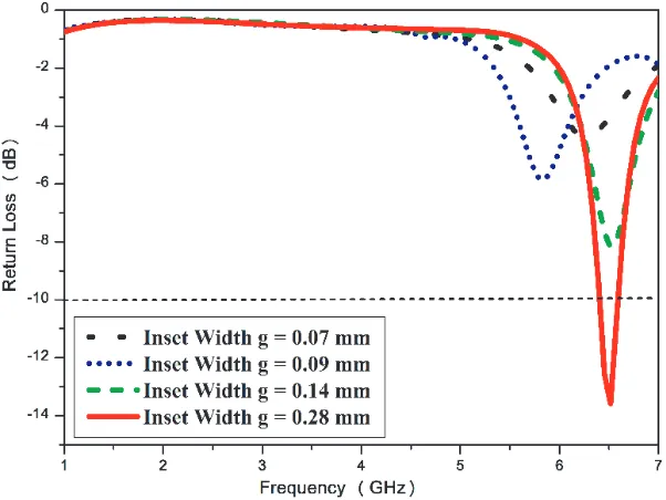
The dimension of the patch is 10×12 mm2. Inset-feed is used to excite the patch antenna. Inset cuts are made in the patch to match the antenna resistance to the feed resistance. The inset gap is Wf/10 whereas the depth is 4.4 mm where Wf — Width of feed line can be seen in Figure 4. The antenna radiates at the fundamental frequency of 6.5 GHz without loading, and the return loss is around
−13.57 dB. The bandwidth is found around 260 MHz. The inset width is varied as Wf/10, Wf/20,
Wf/30, and Wf/40 to yield optimized return loss on fundamental frequency as shown in Figure 4. Thus, the inset width is chosen as Wf/10. Parametric analysis on the patch with and without MSRR loading and the variation in inset fed width to yield optimum dual bands are shown in Figures 4 and 5, respectively.
Figure 4. Parametric analysis for proposed inset fed microstrip patch antenna without MSRR loading for various inset width.
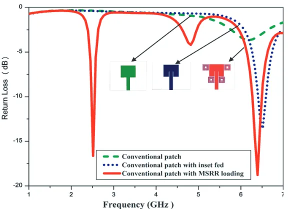
The design starts with conventional patch antenna and results in a fundamental resonance frequency of 6.21 GHz with a return loss of−3.64 dB. The addition of inset fed to the conventional patch antenna results in a frequency swing from 6.21 GHz to 6.5 GHz with a return loss of −13.57 dB. The MSRR structure is placed in adjacent to the rectangular patch where the surface current distribution is more yields another frequency of 2.51 GHz. The fabricated inset fed microstrip patch antenna with MSRR loading is shown in Figure 3. Finally, the MSRR loading not only enhances the basic resonance frequency 6.39 GHZ with a return loss of −18.77 dB but also adds another resonance frequency at 2.51 GHz with a return loss of−16.63 dB as shown in Figure 5.
Figure 5. Parametric analysis of the proposed antenna with conventional patch and with MSRR loading.
the resonant frequency of the SRR. The bandwidth is found to be 130 MHz at 2.52 GHz and 260 MHz at 6.39 GHz with a return loss of−16.16 dB and−17.99 dB at the respective resonant frequencies
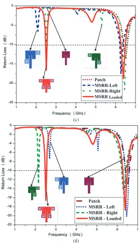
The parametric analysis of different combinations of loading MSRR elements is depicted in Figures 6(a), (b), (c) and (d), respectively. It is observed that the microstrip patch antenna with four MSRR rings results in s new resonance frequency in addition to microstrip’s fundamental frequency.
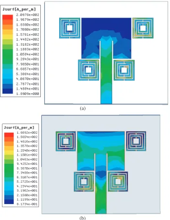
To understand the characteristics of antenna resonant modes, the simulated surface current distributions of the proposed MSRR loaded antenna are illustrated in Figures 7(a) and (b), respectively. At 2.52 GHz, the surface current distribution is good in microstrip feed line and MSRR as shown in Figure 7(a) while at 6.39 GHz the maximum surface current distribution is observed in microstrip patch and feed line shown in Figure 7(b), respectively.
2.1. Quasi Static Analysis
The split gap is one of the vital parameters of the SRR. If the split is removed, the MSRR will not produce any resonance frequency. Inductance of MSRR is due to the metallic strip, and the capacitance is due to the split and gap between the metallic strips. Analytical quasi circuit model is shown in Figure 8. The steps to find the resonant frequency of the MSRR is as follows [8].
The MSRR is placed near the patch antenna. The MSRR shows negative permeability characteristics in the microwave frequency range of interest. The length of the external ring (Ls) is 5 mm; width of the split ring (W) is 0.3 mm; dielectric distance (S) among the rings is 0.2 mm, which is placed over FR4 substrate. Inset feed is used to excite the MSRR loading. The split ring equivalent circuit consists of inductance LMSRR and capacitance CMSRR, given by,
LMSRR =
μ0 2
Lavg 4 4.86
ln0.98
ρ + 1.84ρ
(1)
where
ρ = (NR−1)(W +S) (L1−(NR−1)(W +S) & Lavg = 4 [L1−(NR−1)(W +S)] in which NR is the number of rings, and
CMSRR=
ε0(NR−1) 2
[2L1−(2NR−1)(W +S)]
K1
√
1−k12
K1(k1)
whereK1 is the elliptic integral of the first kind andk1 =S/(S+ 2W).
The above equations are manipulated in MATLAB to approximate the inductance LMSRR and capacitanceCMSRR values of the proposed MSRR loaded antenna. It is appropriate for number of rings in the MSRR greater than one (NR > 1). For NR = 4, L1 = (Ls+Ws)/2 = 5 mm. The computed
LMSRR = 1.72e−08 H and CMSRR = 1.6019e−13 F. Hence, the resonance frequency of MSRR is
fMSRR = 3.0261e+ 09. The theoretical calculated resonance for the proposed MSRR loading antenna is around 3 GHz. The simulated resonant frequency is 2.51 GHz. Hence, there is a small deviation between theoretical resonance frequency and simulated one. Consequently, this resonance frequency is due to the MSRR loading.
(a)
(c)
(d)
Figure 6. Parametric analysis of different combinations of MSRR loading. (a) Unit wise Incremental MSRR loading. (b) Two rings loaded (T) & (B). (c) Two rings loaded pairwise cross inclusion. (d) Two Rings Loaded (L) & (R).
2.2. Extraction of Negative Permeability
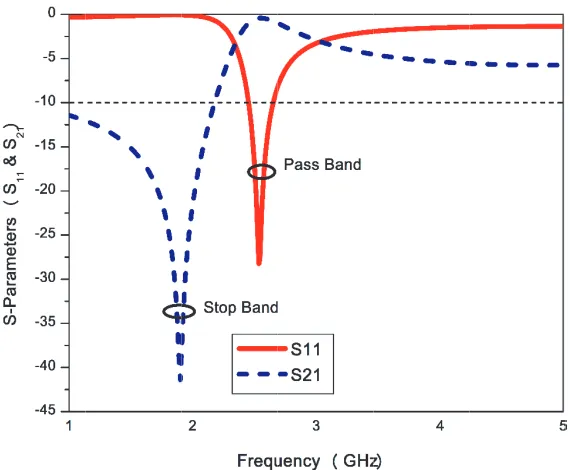
The proposed MSRR loading antenna is evaluated by the reflection coefficient (S11) and transmission coefficient (S21) to obtain the negative permeability characteristics [28–30]. The negative permeability characteristics of the proposed MSRR loading antenna is retrieved using Nicholson-Ross-Weir (NRW) method, shown in Figure 9. The proposed MSRR loading antenna is exerted by the waveguide setup to determine the reflection coefficient S11 and transmission coefficient S21. MATLAB code is written for Equation (1). Therefore, the negative permeability is calculated as,
(a)
(b)
Figure 7. Simulated surface current distribution of proposed MSRR loading antenna. (a) 2.52 GHz, (b) 6.39 GHz.
where
n= 1
kdcos
−1
1 2S21
(1−S112 +S212 )
and z=
(1 +S11)2−S2 21 (1−S11)2−S2
21
(4)
Figure 8. Equivalent circuit analysis of the proposed MSRR loading antenna.
Figure 9. Waveguide setup to retrieve S11 and
S21 parameters of the proposed MSRR loading antenna.
Figure 10. Retrieval ofS11 and S21 parameters.
Table 2. Simulated and measured results of the proposed MSRR loading antenna.
Proposed Antenna
Resonant Frequency
(GHz)
Return Loss (dB)
Impedance Bandwidth
(MHz)
Fractional Bandwidth (%)
Simulated 2.52 −16.16 130 05
6.39 −17.9 260 04
Measured 2.78 −23.91 197 07
Figure 11. Extracted negative permeability characteristics of the proposed MSRR loading antenna.
3. RESULTS AND DISCUSSION
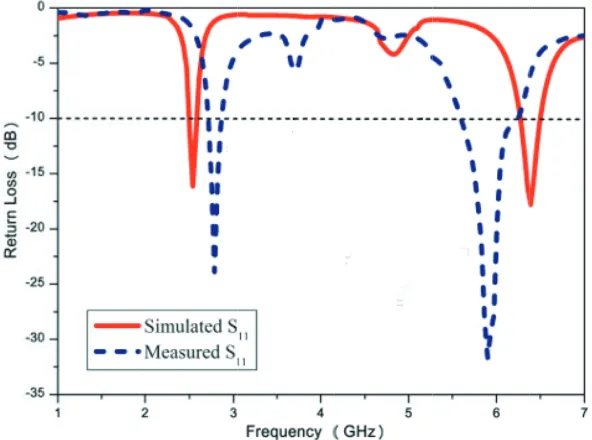
The final design is fabricated as shown in Figure 3. The return loss characteristics are measured using the ENA series E5071C Vector Network Analyzer (VNA). Figure 12 illustrates the simulated and measured return loss characteristics of the proposed inset fed rectangular microstrip patch antenna with MSRR loading.
Figure 12. Simulated and measured return loss characteristics of the proposed inset fed patch antenna with MSRR loading.
(a)
(b)
4. CONCLUSION
A novel inset-fed microstrip rectangular patch antenna with MSRR loading dual-band antenna with compact dimensions of 25× 31 ×1.6 mm3 for WLAN and RF-ID applications is presented. The parameters of the inset-fed antenna with and without MSRR inclusion were used to obtain the optimum resonant frequencies. The loading of MSRR in different probabilities with a rectangular microstrip patch antenna is attributed to achieving a resonant frequency of 2.78 GHz. The metamaterial parameter (μ) is determined negative at 1.9 GHz using effective medium theory approach. Thisμ-negative metamaterial (MNG) is used to obtain compact antenna. An antenna radiating at 2.9 GHz would have a size considerably large compared to the proposed structure. Hence size reduction is achieved. The proposed antenna meets the dual band requirements of 2.78 GHz WLAN and 5.8 GHz RF-ID applications. This paper highlights the metamaterial property and quasi-static analysis to verify all operating bands. Hence, the inset-fed rectangular microstrip patch antenna with MSRR loading dual-band antenna is designed, simulated, fabricated, measured and validated with the experimental design.
ACKNOWLEDGMENT
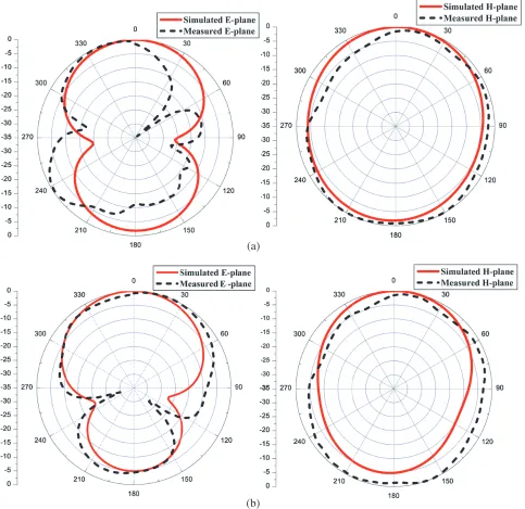
The authors extend their gratefulness to Dr. K. Vasudevan, Emeritus Professor, Department of Electronics, Cochin University of Science and Technology, Kerala, India for carrying out the radiation pattern measurements.
REFERENCES
1. Si, L. M., W. Zhu, and H. J. Sun, “A compact, planar, and CPW-fed metamaterial-inspired dual-band antenna,” IEEE Antennas Wireless Propagation. Letters, Vol. 12, 305–308, 2013.
2. Veselago, V. G., “The electrodynamics of substances with simultaneously negative values of and
μ,”Sov. Phys. Usp, Vol. 10, 509–14, 1968.
3. Christophe, C. and I. Tatsuo, Electromagnetic Metamaterials: Transmission Line Theory and Microwave Applications, Wiley-IEEE Press, New York, 2005.
4. Marqu´es, R., F. Martina, and M. Sorolla,Metamaterials with Negative Parameters: Theory, Design and Microwave Applications, Wiley-Inter Science, 2007.
5. Pendry, J. B., A. J. Holden, D. J. Robbins, and W. J. Stewart, “Magnetismfrom conductors and enhanced nolinear phenomena,” IEEE Transactions on Microwave Theory Technology, Vol. 47, 2075–2084, 1999.
6. Smith, D. R., D. C. Viker, N. Kroll, and S. Schultz, “Direct calculation of permeability and permittivity for a left-handed metamaterial,” Applied Physics Letters, Vol. 77, 2246–2248, 2000. 7. Smith, D. R., W. J. Padilla, D. C. Vier, S. C. Nemat-Nasser, and S. Schultz, “Composite medium
with simultaneously negative permeability and permittivity,”Physics Review Letters, Vol. 84, 4184– 4187, 2000.
8. Bilotti, F., A. Toscano, L. Vegni, K. Aydin, K. B. Alice, and E. Ozbay, “Equivalent circuit models for the design of metamaterials based on artificial magnetic inclusions,” IEEE Transactions on Microwave Theory Technology, Vol. 55, 2865–2872, 2007.
9. Dong, Y. and T. Itoh, “Metamaterial-based antennas,” Proceedings of the IEEE, Vol. 100, No. 7, 2271–2285, 2012.
10. Si, L.-M., H.-J. Sun, Y. Yuan, and X. Lv, “CPW-fed compact planar UWB antenna with circular disc and spiral split ring resonators,” PIERS Proceedings, 502–505, Beijing, China, March 23–27, 2009.
WiMAX/WLAN applications,” IEEE Antennas Wireless Propagation. Letters, Vol. 9, 240–243, 2010.
17. Yang, K., H. Wang, Z. Lei, Y. Xie, and H. Lai, “CPW-fed slot antenna with triangular SRR terminated feed line for WLAN/WiMAX applications,”Electronics Letters, Vol. 47, 685–686, 2011. 18. Quan, X. L., R. L. Li, Y. H. Cui, and M. M. Tentzeris, “Analysis and design of a compact dual-band
directional antenna,” IEEE Antennas and Wireless Propagation Letters, Vol. 11, 547–550, 2012. 19. Pandeeswari, R. and S. Raghavan, “A CPW-fed triple band OCSRR embedded monopole antenna
with modified ground for WLAN and Wi-Max applications,” Microwave and Optical Technology Letters, Vol. 57, 2413–2418, 2015.
20. Sharma, S. K. and R. K. Chaudhary, “Dual-band metamaterial-inspired antenna for Mobile applications,” Microwave and Optical Technology Letters, Vol. 57, 1444–1447, 2015.
21. Rajeshkumar, V. and S. Raghavan, “A compact asymmetric monopole antenna with electrically coupled SRR for WiMAX/WLAN/UWB applications,”Microwave and Optical Technology Letters, Vol. 57, 2194–2197, 2015.
22. Imaculate Rosaline, S. and S. Raghavan, “A compact dual band antenna with an ENG SRR cover for SAR reduction,”Microwave and Optical Technology Letters, Vol. 57, 741–747, 2015.
23. Rajeshkumar, V. and S. Raghavan, “Trapezoidal ring quad-band fractal antenna for WLAN/WIMAX applications,” Microwave and Optical Technology Letters, Vol. 56, 2545–2548, 2014.
24. Kaur, J. and R. Khanna, “Development of dual-band microstrip patch antenna for WLAN/MIMO/WIMAX/ AMSAT/WAVE applications,” Microwave and Optical Technology Letters, Vol. 56, 988–993, 2014.
25. Pandeeswari, R. and S. Raghavan, “Broadband monopole antenna with split ring resonator loaded substrate for good impedance matching,”Microwave and Optical Technology Letters, Vol. 56, 2388– 2392, 2014.
26. Balanis, C. A.,Modern Antenna Handbook, John Wiley and Sons, Inc., 2005.
27. Matin, M. A. and A. I. Sayeed, “A design rule for inset-fed rectangular microstrip patch antenna,”
WSEAS Transactions on Communications, Vol. 9, No. 1, 2010.
28. Smith, D. R., S. Schultz, P. Markos, and C. M. Soukoulis, “Determination of negative permittivity and permeability of metamaterials from reflection and transmission coefficients,” Phys. Review B, Vol. 65, 195104–195109, 2002.
29. Shelby, R. A., D. R. Smith, and S. Schultz, “Experimental verification of a negative index of refraction,” Science, Vol. 292, No. 5514, 77–79, 2001.