A Circularly Polarized Circularly-Slotted-Patch Antenna with Two
Asymmetrical Rectangular Truncations for Nanosatellite Antenna
Peberlin P. Sitompul1, 2, *, Josaphat T. Sri Sumantyo1, Farohaji Kurniawan1, 3, Cahya Edi Santosa1, 3, Timbul Manik2,
Katsumi Hattori4, Steven Gao5, and Jann-Yenq Liu6
Abstract—In this paper, a circularly polarized slot-patch antenna for nanosatellite is presented. The novel design of the circularly polarized wave conducted by two asymmetrical rectangular-truncation techniques implemented on a circularly-slotted-patch on the front side and a deformed-shifted-feedline on the back side of the substrate. The antenna is printed on substrates with the dielectric constant of 2.17 and thickness of 1.6 mm. The resonant frequency of the proposed antenna is set at 2.2 GHz with the minimum requirement of the axial ratio bandwidth (ARBW) of 300 MHz. The proposed antenna produces under 10 dB impedance bandwidth (IBW) 1.2765 GHz or equal to 58% (1.7235–3 GHz) with Left-Handed Circular Polarization (LHCP). The average antenna gain reaches 4.5 dBic at 2.2 GHz and the ARBW 327.5 MHz or about 14.88% (2.0275–2.355 GHz). This paper includes the description and presentation of the completed discussion.
1. INTRODUCTION
The Josaphat Microwave Remote Sensing Laboratory (JMRSL), Center for Environmental Remote Sensing (CEReS), Chiba University has been conducting research and development related to GNSS-RO and Sensor onboard microsatellite for ionosphere monitoring since 2015 [1, 2]. The critical part of the satellite system is an antenna as a radio wave transmitter and receiver. The proposed satellite antenna for ionospheric research is such as [3] by using a quadrifilar helical antenna and [4] with crossed-dipole, but this antenna has unappropriated size for nanosatellite. Thus, an investigation of the characteristics antenna such as small size, light weight, and polarization is necessary. Circularly Polarized (CP) antennas are useful equipment for satellite because of their resilience to multi-path interferences, polarization mismatch, and Faraday rotation effect. Particularly for nanosatellite, the CP and wide beam antennas are very critical, because the angles of elevation and azimuth are uncertain. The CP microstrip antennas have been broadly developed for the satellite antenna by considering its compact size and light weight, which is a critical issue for nanosatellite. Some CP microstrip antennas were discussed in articles such as [5] with six-element stacked patch and [6–9] with equilateral triangular-patch. A circularly-polarized printed antenna is presented in [7, 10] with truncated and triangular-ring slot in the patch, respectively. A CP antenna is presented by using the zeroth-order resonance and modified Alford loop [11]. A CP antenna is presented in [12] with stair-shaped edge and L-shaped feed line.
Received 5 December 2018, Accepted 18 January 2019, Scheduled 5 March 2019
* Corresponding author: Peberlin Parulian Sitompul ([email protected], peberlin [email protected]).
In this paper, a novel design of a circularly polarized antenna with a combination of circular slot and asymmetrical truncation on the patch diagonal is presented. The proposed antenna is printed on a substrate with the thickness of 1.6 mm, dielectric constant of 2.17, and center frequency of 2.2 GHz. The measurement produces a good result with the impedance bandwidth of 1.2765 GHz equal to 58% (1.7235– 3 GHz), while the obtained axial ratio bandwidth is 327 MHz equal to 14.88% (2.0275–2.355 GHz), and the average gain of the antenna is up to 4.5 dBic in the center frequency 2.2 GHz. The minimum requirements of the antenna design are shown in Table 1.
Table 1. The specification of the antenna.
Parameter Value Units
Electrical
Frequency (f) Polarization Axial Ratio (AR) Return Loss (RL)
Gain (G)
2.05–2.35 Circular
≤3
≤ −10
≥4
GHz -dB dB dBic
Mechanical
Weight (W) Thickness (t) Width×Length (W ×L)
<0.2
<10
≤100×100
kg mm mm
2. DETAILED DESIGN OF THE CIRCULARLY-SLOTTED-PATCH ANTENNA WITH TWO ASYMMETRICAL RECTANGULAR TRUNCATIONS
The antenna is printed on a single substrate, which consists of a ground set in the front side and a feedline set on the back side of the substrate. The proposed antenna is designed with a square patch, with size length L of 100 mm and widthW of 100 mm. A circular slot is developed in the patch center with the radius r of 26.5 mm. Two asymmetrical rectangular truncations lie on the diagonal of the patch with Ws of 16 mm as the width of the truncation and Ls1 of 48 mm and Ls2 of 42 mm as the
lengths of the truncation. The dimension of the feeding line is represented byWf1 of 4.5 mm, Wf2 of
10 mm,Lf1 of 40 mm, andLf2 of 8 mm. The detailed geometry of the antenna is shown in Figure 1.
The antenna is designed in 4 models. The conventional model consists of a square patch with a circular slot on patch center with radiusR, feedline widths ofWf1 andWf2, and feedline lengths ofLf1
andLf2. Model 1 consists of a circular slot with the shifted feedlineXf onx-axis. Model 2 consists of a
shifted feedlineXf and two equal-rectangular-truncations ofLs1 and Ls2 on the patch diagonal. Model
3 consists of a shifted feedline of Xf, a deformed feedline in which Wf2 is wider than Wf1 and two
asymmetrical-rectangular-truncations of Ls1 and Ls2 on the patch diagonal. TruncationLs1 is longer
thanLs2 as shown in Figure 1.
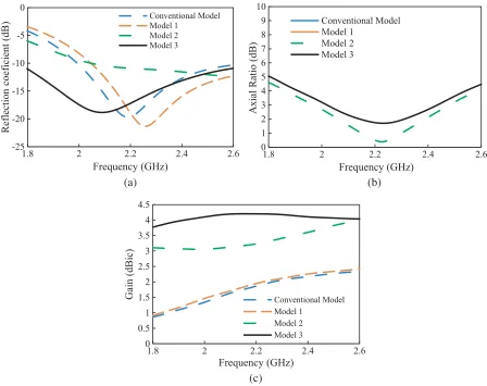
Figure 2 shows steps of designing the proposed antenna as conventional model, model 1, and model 2. The detailed dimensions of the proposed antenna are shown in Table 2. The comparison of the simulation result of the conventional model, model 1, model 2, and model 3 is depicted in Figure 3 and summarized in Table 3.
(a) (b) (c)
Figure 2. Design of the antenna models. (a) Conventional model. (b) Model 1. (c) Model 2.
Table 2. Dimensions of antenna models.
Models L (mm)
W
(mm)
R
(mm)
Ls1
(mm)
Ls2
(mm)
Wf1
(mm)
Wf2
(mm)
Xf1
(mm) Conventional
Model 100 100 26.5 no slot no slot 3.8 3.8 0 Model 1 100 100 26.5 no slot no slot 3.8 3.8 −5
Model 2 100 100 26.5 45 45 4.5 10 −5
Model 3 100 100 26.5 48 42 4.5 10 −5
Table 3. Simulation result of conventional model, model 1, model 2 and model 3.
Models fcibw (GHz)
IBW (GHz), %
fcarbw
(GHz)
3-dB ARBW (GHz), %
0 0.5 1 1.5 2 2.5 3 3.5 4 4.5
1.8 2 2.2 2.4 2.6
Gain (dBic)
Frequency (GHz)
Conventional Model Model 1
Model 2 Model 3 -25
-20 -15 -10 -5 0
1.8 2 2.2 2.4 2.6
Reflection coeficient
(dB)
Frequency (GHz)
Conventional Model Model 1
Model 2 Model 3
0 1 2 3 4 5 6 7 8 9 10
1.8 2 2.2 2.4 2.6
A
xial R
atio
(dB)
Frequency (GHz)
Conventional Model Model 1
Model 2 Model 3
(a) (b)
(c)
Figure 3. Performance comparison of (a) reflection coefficient (S11), (b) axial ratio and (c) antenna
gain of conventional model, model 1, model 2, model 3.
2.1. Effect of the Shifted-Feedline and Two Rectangular-Truncations
The proposed antenna is a square patch circularly-slotted on patch center and two-rectangular truncations on the diagonal of the patch. The unique design of this antenna lies on the two-rectangular truncations on the grounded plane and a shifted and deformed feedline to generate CP waves and enhance the antenna gain. The antenna is designed with a single layer, where the front layer is set as a ground, and then the back layer is configured as the feedline. The antenna is etched on the substrate with dielectric constant of 2.17, thicknessh of 1.6 mm, and loss of tangent of 0.0005.
Presently, many methods are applied to generate CP waves such as by equilateral triangular microstrip patch with [8, 9] the dual-feeding method and [10] the single feed [14] by inserting slits of different lengths at the edges of a square patch. The others for generating CP waves with a slot antenna presented by [15] using single feed cross slot, [16, 17] by a narrow slot or across slot with unequal slot lengths with single feed, [18] by single feed with a rectangular center slot, [19] by single feed with arc-shaped slot, [20] by slanted rectangular slot, and [21] by space-filling-based slot antenna. In this design, the circular slot patch with two rectangular truncations and the shifted-deformed feedline are proposed to generate CP waves and to enhance the antenna gain. The variety of the feedline position Xf on the x-axis and the rectangular slot lengths Lf1 and Lf2 on the y-axis is presented in
this section to complete the investigation. The simulation results of the shifted-feedline and the two equal-rectangular-truncations for the reflection coefficient S11, axial ratio, and the antenna gain with
-20 -18 -16 -14 -12 -10 -8 -6 -4 -2 0
1 1.2 1.4 1.6 1.8 2 2.2 2.4 2.6 2.8 3 3.2 3.4
S11 (
dB)
Frequency (GHz) Xf = 0 mm
Xf = -5 mm Xf = -14 mm
0 1 2 3 4 5 6 7 8 9 10
1 1.2 1.4 1.6 1.8 2 2.2 2.4 2.6 2.8 3 3.2 3.4
A
xial
Ratio
(
dB)
Frequency (GHz) Xf = 0mm
Xf = 5mm Xf = -14mm
0 0.5 1 1.5 2 2.5 3 3.5 4 4.5
1 1.2 1.4 1.6 1.8 2 2.2 2.4 2.6 2.8 3 3.2 3.4
Ga
in
(
dB
ic
Frequency (GHz) Xf =0mm
Xf =-5mm Xf =-14mm
(a) (b)
(c)
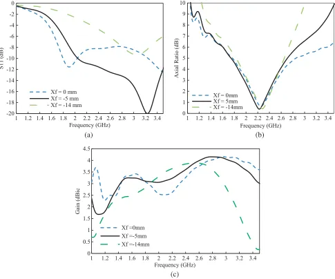
Figure 4. Variation of the shifted-feedline and the equal-rectangle-truncation to (a) the reflection coefficient, S11, (b) the axial ratio, (c) the antenna gain.
shifting Xf of 0 mm, −5 mm, and −14 mm to the reflection coefficient S11. The feedline is on Xf of
0 mm, and it can produce the reflection coefficient, S11<−10 dB of 1.79–2.06 GHz and 3.26–3.87 GHz.
The center of frequency is 1.9 GHz and 3.57 GHz, with the deepest curve which is obtained at−11.5 dB and −12.66, respectively.
When the feedline shifts Xf to −5 mm, it can produce the impedance bandwidth of reflection
coefficient, S11<−10 dB of 2.06–3.57 GHz. The center of frequency is 3.2 GHz, with the deepest curve
which is obtained at −20 dB. When the feedline shifts Xf to −14 mm, it cannot produce the reflection
coefficient, S11 < −10 dB. The simulation result shows that the possible feedline position is between
0 mm and −14 mm. If the feedline is shifted less than 0 mm and more than −14 mm of the x-axis, it cannot produce the reflection coefficient, S11 < −10 dB. Figure 4(b) shows the effect of the feedline
shifting Xf to 0 mm, −5 mm, and −14 mm on the axial ratio (AR). With the feedline on Xf of 0 mm,
it can produce the axial ratio bandwidth AR < 3 dB up to 22.2% of 2.02–2.52 GHz. The center of frequency is 2.25 GHz, with the deepest curve of 0.58 dB. When the feedline is shifted to left side of
The center of frequency is 2.28 GHz, with the deepest curve of 0.42 dB. The simulation result shows that feedline shifting has insignificant effects on the axial ratio. Figure 4(c) shows the effect of the feedline shiftingXf to 0 mm,−5 mm, and−14 mm on the antenna gain. When the feedline is onXf of 0 mm, it
can only reach 2.6 dBic at frequency of 2.2 GHz with a peak gain of 4 dBic at frequency 3 GHz. When the feedline is shifted to−5 mm, it can reach the antenna gain>3 dBic at 1.42–3.5 GHz with the peak curve of 4.15 dBic at frequency 2.8 GHz. When the feedline is shifted to−14 mm, it reaches the antenna gain of 3.6 dBic at 2.2 GHz with peak gain of 3.88 dBic at 2.5 GHz. The simulation result shows that the shifted feedline has very significant correlation to the reflection coefficientS11and antenna gain.
2.2. Optimizing the Reflection Coefficient (S11) and the Gain by the Feedline Tuning
Methods to optimize the reflection coefficient are presented in [22] by using a skew metallic surface and in [23] by varying the slot length. In this design, the reflection coefficientS11and gain optimization are
implemented by two methods; firstly by shifting the feedline and by the two rectangular truncations; secondly by applying the deformed feedline. The design by shifted-feedline and the two-rectangular-truncations has already been explained in the previous section.
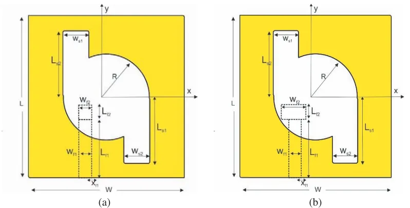
Figure 5 shows the feedline designs in different sizes. The design is created into three designs. Design 1 is square-shaped with width Wf1 of 3.8 mm, Wf2 of 3.8 mm, length Lf1 of 40 mm, and Lf2
of 8 mm. Then, design 2 is a square-shaped one with widthWf1 of 5 mm,Wf2 of 5 mm, length Lf1 of
40 mm, andLf2 of 8 mm. Design 3 is obtained by changing the widthWf1 narrower of 4.5 mm andWf2
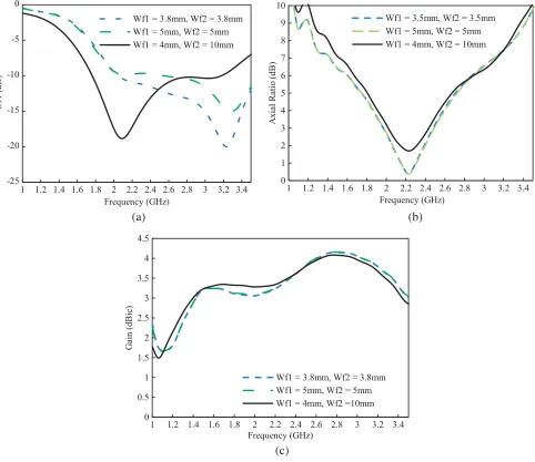
wider of 10 mm. Focus of this section is to investigate the feasibility of the diversity on feedline sizes. In general, all the feedline models can produce peak gain up to 4 dBic. Figure 6 shows the effect of the feedline design on the reflection coefficientS11, axial ratio, and antenna gain with fixed truncation
lengthsLs1 and Ls2 of 45 mm, respectively.
(a) (b)
Figure 5. The feedline design in different sizes. (a) Design 1, the feedline width Wf1 and Wf2 of
3.8 mm; Design 2, Wf1 and Wf2 of 5 mm. (b) Design 3Wf1 of 4.5 mm and Wf2 of 10 mm.
Figure 6(a) depicts the reflection coefficient S11 of design 1, design 2, and design 3. Design 1 has
the impedance bandwidth of 2.067–3.576 GHz, with the deepest curve of−19.99 dB on center frequency (fcibw) of 3.234 GHz. Design 2 has the impedance bandwidth of 2.556–3.576 GHz, with the deepest curve with S11 of −15 dB at frequency 3.286 GHz. This design shifts the center frequency to a higher
frequency of 3.286 GHz. Design 3 has impedance bandwidthS11 of 1.782–3.169 GHz, with the deepest
curve withS11of −18.8 dB at the center frequency of 2.11 GHz. This last model has succeeded to shift
-25 -20 -15 -10 -5 0
1 1.2 1.4 1.6 1.8 2 2.2 2.4 2.6 2.8 3 3.2 3.4
S11 (
dB)
Frequency (GHz)
Wf1 = 3.8mm, Wf2 = 3.8mm Wf1 = 5mm, Wf2 = 5mm Wf1 = 4mm, Wf2 = 10mm
0 0.5 1 1.5 2 2.5 3 3.5 4 4.5
1 1.2 1.4 1.6 1.8 2 2.2 2.4 2.6 2.8 3 3.2 3.4
G
ain (
dBic
)
Frequency (GHz)
Wf1 = 3.8mm, Wf2 = 3.8mm Wf1 = 5mm, Wf2 = 5mm Wf1 = 4mm, Wf2 =10mm
0 1 2 3 4 5 6 7 8 9 10
1 1.2 1.4 1.6 1.8 2 2.2 2.4 2.6 2.8 3 3.2 3.4
A
xial
Ratio
(
dB)
Frequency (GHz)
Wf1 = 3.5mm, Wf2 = 3.5mm Wf1 = 5mm, Wf2 = 5mm Wf1 = 4mm, Wf2 = 10mm
(a) (b)
(c)
Figure 6. Effect of the feedline design; design 1, design 2 and design 3 related to (a) reflection coefficient, S11, (b) axial ratio, (c) antenna gain.
Table 4. The antenna performance with the feedline form design.
Designs fcibw (GHz)
Impedance Bandwidth (GHz), %
fcarbw
(GHz)
3-dB ARBW (GHz), %
Peak Gain (dBic) Design 1 3.238 20623579, 46.84 2.25 1.980–2.487, 22.53 4.08 Design 2 3.286 2556–3579, 31.13 2.23 1.979–2.480, 22.46 4.08 Design 3 2.11 1773–3.169, 66.1 2.23 2.02–243, 18.38 4.079
the antenna generates similar axial ratios of 1.9–2.4 GHz with the deepest curve of 0.36 dB on center frequency (fcarbw) of 2.25 GHz. With the feedline width Wf1 of 4 mm andWf2 of 10 mm, the antenna
0.80 0.85 0.90 0.95 1.00
1.7 1.8 1.9 2 2.1 2.2 2.3 2.4 2.5 2.6 2.7 2.8 2.9 3
Efficiency
,
η
(%
)
Frequency (GHz)
Ls1=28mm, Ls2 =25mm Ls1=25mm, Ls2=25mm Ls1=28mm, Ls2=28mm
Figure 7. Effect of the rectangular lengthLs1 and Ls2 related to radiation efficiency.
The simulated result shows that the center of impedance frequency is very sensitive to the feedline design variation. Among all designs, design 3 shows a similar frequency to the center frequency of 2.11 GHz. This design is called model 2. However, the weakness of this model is that antenna gains on 2.2 GHz reach up to 3.3 dBic. Modification of rectangular length ofLs1 of 45 mm to be longer of 48 mm
andLs2 of 45 mm to be shorter of 42 mm has succeeded to enhance the antenna gain from 3.3 dBic to be
higher of 4.2 dBic. This model is called as model 3. The dimension and simulation result of conventional model, model 1, model 2, and model 3 are shown on Table 2 and Table 3.
Figure 7 shows the effect of the rectangular lengthsLs1 andLs2 related to radiation efficiency. The
radiation efficiency (η) in 2–2.4 GHz is more than 95%. Theη variations are similar withLs1 of 25 mm
or 28 mm andLs2 of 25 mm or 28 mm, respectively, but withLs1 of 28 mm andLs2 of 25 mm,η is better
in frequency of 2.4–3 GHz.
3. FABRICATION AND MEASUREMENT RESULT
The fabrication and measurement must be conducted to verify the simulated result. In this case, circumspection is required to produce a precise antenna and a good measurement result. Figure 8
(a) (b)
0 1 2 3 4 5 6 7 8
1.7 1.8 1.9 2 2.1 2.2 2.3 2.4 2.5 2.6 2.7 2.8 2.9 3
A
xial Ratio
(dB
)
Frequency (GHz)
Measurement Simulation
-20 -18 -16 -14 -12 -10 -8 -6 -4 -2 0
1.7 1.8 1.9 2 2.1 2.2 2.3 2.4 2.5 2.6 2.7 2.8 2.9 3
Reflection Coeficient
(dB)
Frequency (GHz)
Measurement Simulation
0 1 2 3 4 5 6
1.7 1.8 1.9 2 2.1 2.2 2.3 2.4 2.5 2.6 2.7 2.8 2.9 3
Gain (dBic)
Frequency (GHz)
____ Measurement
- - - - Simulation
(a) (b)
(c)
Figure 9. (a) Axial ratio. (b) Reflection coefficient, S11 and (c) antenna gain of the simulated result
against the measured result.
shows the fabricated antenna that has a total dimension of 100 mm×100 mm×1.6 mm. Figure 9(a) depicts the comparison of the axial ratios of measured and simulated results. The results have a good agreement in which the measurement result can produce the ARBW of 327.5 MHz or equal to 14.88% (20275–2355 GHz), and the deepest point of the curve on 2.22 GHz is 2 dB. The simulated result can produce the ARBW of 410 MHz or equal to 22.62% (1.960–2.460 GHz), and the deepest point of the curve on 2.235 GHz is 1.747 dB. The simulated and measured results meet the suitability. The minimum requirement of the bandwidth of the reflection coefficient is under 10 dB at 400 MHz. As shown in Figure 9(b), the simulation and measurement can produce acceptable results compared to the minimum requirement. The measured impedance bandwidth is up to 1.2765 GHz or equal to 58% (1.7235 GHz–3 GHz). At the center frequency 2.2 GHz, the result is up to −17.14 dB, while the deep curve is at 2.04 GHz of −18.22 dB. The measured impedance bandwidth is better than the simulated one.
frequency of 2.2 GHz, it yields 5.3 dBic, while in the higher frequency of 2.3 GHz, it is 3.8 dBic. There is a sinusoidal wave like curve on the antenna gain. In the frequency less than 2.2 GHz, it is shown that the measured result is higher than the simulated one, but at the frequency more than 2.2 GHz, it is shown that the measured result is lower than the simulated one.
0°
330°
300°
270°
240°
210° 180°
150° 120° 90°
60° 30°
-40 -30 -20 -10 0
2 GHz
0°
330°
300°
270°
240°
210° 180°
150° 120° 90°
60° 30°
-40 -30 -20 -10 0
2.2 GHz
0°
330°
300°
270°
240°
210° 180°
150° 120° 90°
60° 30°
-50 -40 -30 -20 -10 0
2.4 GHz
PLRPLT_BASE PLRPLT_SPOKES E-LHCP (Measured) E-LHCP (Simulated) E-RHCP (Measured) E-RHCP (Simulated) (a) E-plane of 2 GHz (b) E-plane of 2.2 GHz
(c) E-plane of 2.4 GHz
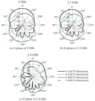
Figure 10. The measured and simulated radiation pattern of the proposed antenna. (a) 2 GHz, (b) 2.2 GHz (c) 2.4 GHz.
Table 5. Comparison of CP printed antenna performances in S-band.
Ref. fc (GHz) ARBW (%)3-dB Bandwidth (%)Impedance Gain(dB) Dimension (mm)Diameter (d)
[7] 1.840 37 44 3 to 5.8 150×170×1.6
[8] 1.27 0.58 19.5 6.4 146×163×3.2
[11] 2.4 54 6 1.5 (d×h) 48×9
[12] 2.45 25.8 42 3.8 52×52×1
[13] 1.227/1.575 13/10.15 3.1/3.2 8/7.5 150×78×25
[15] 2.25 13.7 101 5.6 170×170×1.6
Figure 10 shows the LHCP on 0-degree and the RHCP on 180-degree radiation pattern at three discrete frequencies of 2 GHz, 2.2 GHz, and 2.4 GHz. The measured and simulated results show a similar pattern at the lower frequency of 2 GHz, the center frequency of 2.2 GHz, and higher frequency of 2.4 GHz. Dimension and performances in S-band of the measured antenna are compared with those of some related CP printed antennas listed in the literature as shown in Table 5.
4. CONCLUSION
The shifted-deformed feedline and two asymmetrical rectangular truncations have managed to enhance the performance of the proposed antenna. It produces a good impedance bandwidth, axial ratio bandwidth, and antenna gain. The deformed feedline has achieved the performance of the impedance bandwidth and has shifted the center frequency close to 2.2 GHz. Evidently, two asymmetrical rectangular truncations with LS1 of 48 mm and LS2 of 42 mm can enhance the measured impedance
bandwidth of 1.276 GHz or equal to 58% (1.723–3 GHz) and 3-dB ARBW which obtains 14.88% (2.027– 2.35 GHz) and the measured antenna gain up to 4.5 dBic at 2.2 GHz. This novel antenna design has a good performance.
ACKNOWLEDGMENT
This research is supported in parts by the Chiba University Strategic Priority Research Promotion Program FY2016-FY2018; Indonesian National Institute of Aeronautics and Space (LAPAN); and Ministry of Research, Technology and Higher Education (RISET-PRO).
REFERENCES
1. Sri Sumantyo, J. T. and N. Imura, “Development of GNSS-RO and EDTP sensors onboard microsatellite for Ionosphere monitoring,” IGARSS, 2015.
2. Sri Sumantyo, J. T., “Development of microsatellites for atmospheric and land deformation observation,” Asia Oceania Geoscience Symposium (AOGS), 219, July 28, 2014.
3. Pansomboon, R., C. Phongcharoenpanich, and R. Phudpong, “Design of a dual-band quadrifilar helical antenna for radio beacon receiver,” ISPACS, 2011.
4. Bernhardt, P. A. and C. L. Siefring, “New satellite-based systems for ionospheric tomography and scintillation region imaging,”Radio Science, Vol. 41, RS5S23, 2006, doi:10.1029/ 2005RS003360. 5. Sri Sumantyo, J. T., K. Ito, D. Delaune, H. Yoshimura, and T. Tanaka, “Simple satellite-tracking
dual-band triangular-patch array antenna for ETS-VIII applications,”APS Conference, 2004. 6. Sri Sumantyo, J. T., K. Ito, and M. Takahashi, “Dual-band circularly polarized equilateral
triangular-patch array antenna for mobile satellite communications,” IEEE Transactions on
Antennas and Propagation, Vol. 53, No. 11, 3477–3485, November 2005.
7. Awaludin, A., J. T. Sri Sumantyo, C. E. Santosa, and M. Z. Baharuddin, “Axial ratio enhancement of equilateral triangular-ring slot antenna using coupled diagonal line slots,”Progress
In Electromagnetics Research C, Vol. 70, 99–109, 2016.
8. Baharuddin, M., V. Wissan, J. T. Sri Sumantyo, and H. Kuze, “Equilateral triangular microstrip antenna for circularly-polarized synthetic aperture radar,”Progress In Electromagnetics Research C, Vol. 8, 107–120, 2009.
9. Suzuki, Y., N. Miyano, and T. Chiba, “Circularly polarised radiation from singly fed equilateral-triangular microstrip antenna,” Microwaves, Antennas and Propagation, IEEE Proceedings, Vol. 134, No. 2, 194–198, April 1987.
11. Yang, L., N. W. Liu, Z. Y. Zhang, G. Fu, Q. Liu, and S.-L. Zuo, “A novel single feed omnidirectional circularly polarized antenna with wide AR bandwidth,”Progress In Electromagnetics Research C, Vol. 51, 35–43, 2014.
12. Chen, L., X. Ren, Y. Yin, and Z. Wang, “Broadband CPW-fed circularly polarized antenna with an irregular slot for 2.45 GHz RFID reader,” Progress In Electromagnetics Research Letters, Vol. 41, 77–86, 2013.
13. Cai, Y. M., K. Li, Y. Z. Yin, and X. Ren, “Dual-band circularly polarized antenna combining slot and microstrip modes for GPS with HIS ground plane,”IEEE Antennas and Wireless Propagation
Letters, Vol. 14, 1129–1132, 2015.
14. Wong, K. L. and J. Y. Wu, “Single-feed small circularly polarized square microstrip antenna,”
Electron. Letter., Vol. 33, 1833–1834, October 23, 1997.
15. Kurniawan. F., J. T. Sri Sumantyo, G. S. Prabowo, and A. Munir, “Wide bandwidth left-handed circularly polarized printed antenna with crescent slot,”2017 Progress In Electromagnetics Research
Symposium — Spring (PIERS), 1047–1050, Russia, 2017.
16. Iwasaki, H., “A circularly polarized small-size microstrip antenna with a cross slot,” IEEE
Transactions on Antennas and Propagation, Vol. 44, No. 10, 1399–1401, October 1996.
17. Lu, J. H., C. L. Tang, and K.-L. Wong, “Single-feed slotted equilateral-triangular microstrip antenna for circular polarization,”IEEE Transactions on Antennas and Propagation, Vol. 47, No. 7, 1174–1178, July 1999.
18. Kurniawan, F., J. T. Sri Sumantyo, K. Ito, H. Kuze, and S. Gao, “Patch antenna using rectangular centre slot and circular ground slot for Circularly Polarized Synthetic Aperture Radar (CP-SAR) application,”Progress In Electromagnetics Research, Vol. 160, 51–61, 2017.
19. Hsieh, G., M. Chen, and K. Wong, “Single-feed dual-band circularly polarized microstrip antenna,”
Electronics Letters, Vol. 34, No. 12, 1170–1171, 1998.
20. Aziz, M. Z. A., N. A. D. A. Mufit, M. K. Suaidi, A. Rahim, and M. R. Kamaruddin, “Design X-circular polarized with slanted rectangular slot by using single port,”Proceedings of ISAP, Nagoya, Japan, 2012.
21. Ghali, H. A. and T. A. Moselhy, “Broad-band and circularly polarized space-filling-based slot antennas,” IEEE Transactions on Microwave Theory and Techniques, Vol. 53, No. 6, 1946–1950, June 2005.
22. Valagiannopoulos, A. C., “Electromagnetic propagation into parallel-plate waveguide in the presence of a skew metallic surface,” International Journal of Applied Electromagnetics and
Mechanics, 31, 2009.
23. Chang. T. and J. Lin, “Circularly polarized antenna having two linked slot-rings,” IEEE