Available online: https://edupediapublications.org/journals/index.php/IJR/ P a g e | 283
Power Controllability of a Three-Phase Converter with an
Unbalanced Ac Sourc
Mr.Aravind Samanu & Ms.K.Lakshmi
1 PG Student, Dept. Of Power Electronics , SKR College Of Engineering & Technology, AP. 2 Asst. Professor, Dept. Of Power Electronics, SKR College Of Engineering & Technology,
AP.
Abstract- This paper explains the power controllability of three phase converter with an unbalanced AC source by using fuzzy logic controller. Three-phase DC-AC power converters suffer from power oscillation and over current problems in case of unbalanced AC source voltage that can be caused by grid/generator faults. Existing solutions to
handle these problems are properly
selecting and controlling the positive and negative sequence currents. In this work a new series of control strategies which utilize the zero-sequence components are proposed to enhance the power control ability under this adverse condition. A fuzzy logic controller is rule based logic; it is having more advantages than other controllers. By using fuzzy logic controller we get required output. It is concluded that by introducing proper zero sequence current controls and corresponding circuit configurations, the power converter can enable more flexible
control targets, achieving better
performances in the delivered power and
load current when suffering from
unbalanced AC source.
Index Terms— DC-AC converter, Unbalanced AC source, Control strategy, Fault tolerance, fuzzy logic controller.
I. INTRODUCTION
In many important applications for power electronics such as power generation, motor drives, power quality, etc., the three-phase DC-AC converters are important part as the backbone interface between DC and AC electrical systems [1],As shown in Fig.
1, a typical DC-AC voltage source converter is used to convert the energy between the DC bus and the three-phase AC sources, which could be the power grid, generation units or the electric machines depending on the applications [3]-[5].
Since the power electronics are getting so widely used and becoming essential in the energy conversion technology, the failures or shutting down of these backbone DC-AC converters may result in serious problems and cost. It is becoming a need in many applications that the power converters should be reliable to withstand some faults or disturbances in order to ensure certain availability of the energy supply [6]-[13].
When the voltages become distorted and unbalanced under faults or disturbances, the unbalanced AC voltages have been proven to be a
Available online: https://edupediapublications.org/journals/index.php/IJR/ P a g e | 284
Fig. 1. A typical DC-AC converter application This paper targets to improve the power control limits of typical three-phase DC-AC converter system under unbalanced AC source (e.g. grid or generator with voltage dips). A new series of control strategies which utilizes the zero-sequence components are then proposed to enhance the power control ability under this adverse condition.
II.CONVERTER SYSTEM WITH THE ZERO SEQUENCE CURRENT PATH
As can be finished up, in the typical three-stage three-wire converter structure, four control flexibilities for the load current appear to be insufficient to accomplishattractive exhibitions under the uneven air conditioning source. (Regardless of what mixes of control targets are utilized, either
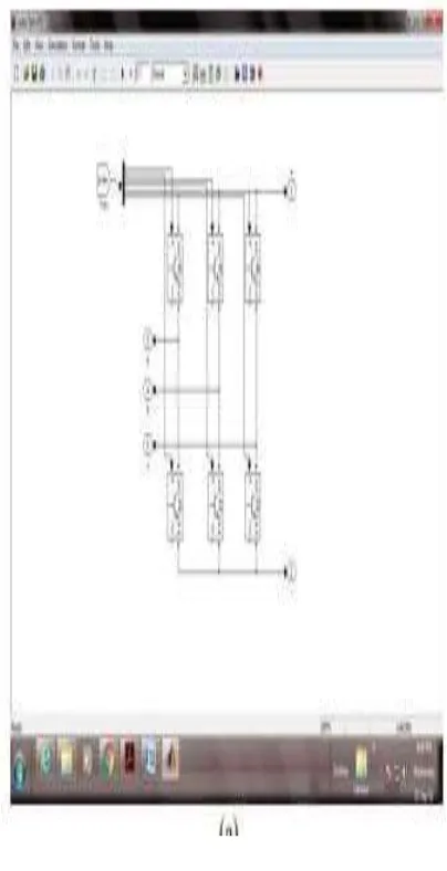
huge power swaying or over-burden/mutilated current will be displayed.) Therefore, more present control flexibilities are required so as to enhance the control execution under the unequal air conditioning source conditions. Another arrangement of the converter structure are appeared as demonstrated as the four-wire framework in Fig. 9(a) and the six-wire framework in Fig. 9(b). Contrasted with the three-wire converter structure, these sorts of converters present the zero-sequence current path, which may empower additional present control flexibilities to accomplish better power control exhibitions. It is noticed that in the framework associated application, the zero- sequence current isn't infused into the
Available online: https://edupediapublications.org/journals/index.php/IJR/ P a g e | 285
Fig.4. Converter structure with the zero-sequence current path. (a) Four-wire system. (b) Six-wire system
Fig.5. Control structure for the converter system with the zero-sequence current
A potential control structure is proposed in which an extra control loop is introduced to enable the controllability of the zero-sequence current. After introducing the regulated zero-sequence current, the three-phase current generated by the converter can be written as
By operating the voltage of the ac source (1) and the current controlled by the power converter(2), the instantaneous generated real power p, the imaginary power q in the αβ coordinate, and the real power p0 in the zero coordinate can be calculated as
Then, the instantaneous three-phase real power p3Φ and the imaginary power q3Φ of the converter can be written as
Available online: https://edupediapublications.org/journals/index.php/IJR/ P a g e | 286
Then, matrix equation as
It is noted that unlike the traditional approach in which the zero sequence components are normally minimized, the zero sequence voltage and the current here look like single-phase AC components running at the same fundamental frequency. As a result, the zero-sequence voltage/current can be represented by vectors in a synchronous reference frame in the zero sequence as
where the real part and imaginary part can be represented as follows:
It can be seen that if the three-phase ac source voltage is decided, then the converter has six controllable freedoms (i+ d ,i+q , i− d , i− q , i0 Re, and i0 Im ) to regulate the current flowing in the ac source. That means: six control targets/functions can be established by the converter having the zero-sequence current path. Similarly, the three-phase average active and reactive power delivered by the converter are two basic requirements for a given application, then, two control functions need to be first settled
as So, for the converter system with the zero-sequence current path, there are four control freedoms left to achieve two more control targets than the traditional three-wire system, this also means extended controllability and better performance under the unbalanced ac source.
III.ELIMINATION OF BOTH THE ACTIVE AND REACTIVE POWER OSCILLATION
Because of more current control freedoms, the power converter with the zero-sequence current path can not only eliminate the oscillation in the active power, but also cancel the oscillation in the reactive power at the same time. This control targets can be written as
The power oscillation caused by the zero-sequence current P0c2 and P0s2 are used to compensate the power oscillation caused by the positive- and negative-sequence currents Pc2 and Ps2.
Available online: https://edupediapublications.org/journals/index.php/IJR/ P a g e | 287
all of the controllable current components with the zero-sequence current path can be solved by
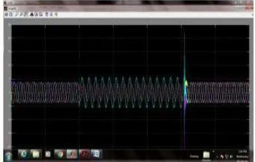
Fig.6. Simulation of converter control with no active and reactive power oscillation (three-phase converter with the zero-sequence path, Pref = 1 p.u., Qref = 0 p.u., Ps2 = 0 p.u., Pc 2 = 0 p.u., Qs2 = 0 p.u., Qc 2 = 0 p.u., VA = 0 p.u.). A. Elimination of
the Active Power Oscillation and the Negative-Sequence Current
And each of the current components can be calculated as
In order to facilitate the analytical solution, assuming that the d-axis or the real axis in the synchronous reference frame is allied with the voltage vectors in each of the sequence, then all of the controllable current components with the zero sequence current path can be solved as
It is noted that the converter has to deliver constant positive- and zero-sequence currents in order to achieve this control strategy under different dips of the source voltage. The oscillation of the reactive power is maintained in a much smaller range (up to 0.3 p.u.) compared to that in the three wire system (up to 1.3 p.u.) in Fig9(b). The zero-sequence current is controlled as zero when the voltage dip is at 1.0 p.u
IV.EXPERIMENTAL RESULTS
The control results by different converter structures and control strategies are
validated on a downscale dc–ac converter. As shown in Fig. 15, the circuit configurations and setup photo are both illustrated. A three-phase two-level converter with corresponding LCL filter is used to interconnect two dc voltage sources and a programmable three-phase ac voltage source. The amplitude of the phase A voltage in the programmable ac source is adjusted to 0.1 p.u. (22 Vrms ) in order to establish an adverse unbalanced condition.
Available online: https://edupediapublications.org/journals/index.php/IJR/ P a g e | 288
= 0 p.u., iq− = 0 p.u.). (a) Sequence current amplitude versus VA . (b) P and Q ranges versus VA .
.
Fig.8. Configurations of the experimental setup. (a) Circuit topology
Available online: https://edupediapublications.org/journals/index.php/IJR/ P a g e | 289
V.CONCLUSION:
In a regular three-stage three-wire converter structure, there are four current control flexibilities, and it might be insufficient to accomplish tasteful exhibitions under the unequal air conditioning source, in light of the fact that either altogether the wavered control or the over-burden current will be introduced. In the three-stage converter structure with the zero grouping current way, there are six current control opportunities. The additional two control opportunities originating from the zero grouping current can be used to expand the controllability of the converter and enhance the control execution under the uneven air conditioning source. By the proposed control techniques, it is conceivable to thoroughly cross out the swaying in both the dynamic and the responsive control, or diminished the swaying sufficiency in the receptive control. Then, the present adequacy of the flawed stage is altogether
assuaged without additionally expanding the current abundancy in the ordinary stages. The favorable position and highlights of the proposed controls can be as yet kept up under different conditions while conveying the receptive power. The examination what's more, proposed control strategies are very much concurred by trial approvals.
VI.BIBLIOGRAPHY
[1] F. Blaabjerg, M. Liserre, K. Ma, “Power Electronics Converters for Wind Turbine Systems,” IEEE Trans. on Industry Applications, vol. 48, no. 2, pp. 708-719, 2012.
[2] R. Teodorescu, M. Liserre, P. Rodriguez, Grid Converters for Photovoltaic and Wind Power Systems, Wiley-IEEE press, 2011.
Available online: https://edupediapublications.org/journals/index.php/IJR/ P a g e | 290
[4] J. W. Kolar, T. Friedli, “The Essence of Three-Phase PFC Rectifier Systems—Part I,” IEEE Trans. on Power Electronics,Vol. 28, No. 1, pp. 176-198, Jan 2013.
[5] Jiabing Hu, Lei Shang, Yikang He, Z.Z. Zhu, “Direct Active and Reactive Power Regulation of Grid-Connected DC/AC Converters Using Sliding Mode Control Approach,” IEEE Trans. on Power Electronics,Vol. 26, No. 1, pp. 210-222, Jan 2011.
[6] C. Wessels, F. Gebhardt, F.W. Fuchs, “Fault Ride-Through of a DFIG Wind Turbine Using a Dynamic Voltage Restorer During Symmetrical and Asymmetrical Grid Faults,” IEEE Trans. on Power Electronics, Vol. 26, No. 3, pp. 807-815, Mar 2011.
[8] F. Aghili, “Fault-Tolerant Torque Control of BLDC Motors,” IEEE Trans. on Power Electronics,Vol. 26, No. 2, pp. 355-363, Feb 2011.an Xiangwu, G. Venkataramanan,Wang Yang, Dong Qing, Zhang Bo, “Grid-Fault Tolerant Operation of a DFIG Wind Turbine Generator Using a Passive Resistance Network,” IEEE Trans. on Power Electronics,Vol. 26, No. 10, pp. 2896-2905, Oct 2011.
[9] B.A. Welchko, T.A. Lipo, T.M. Jahns, S.E. Schulz, “Fault tolerant three-phase AC motor drive topologies: a comparison of features, cost, and limitations,”IEEE Trans. on Power Electronics,Vol. 19, No. 4, pp. 1108- 1116, 2004.
[10] F. Blaabjerg, K. Ma, D. Zhou, "Power electronics and reliability in renewable
energy systems", Proc. of ISIE 2012, pp. 19 - 30, May 2012.
Author’s Profile:
Mr.S.ARAVIND
receiv ed B.Tech in Electrical andElectronics Engineering
from Sri Raghavendra
institute of Science &
Technology Engineering
College, Vinjamur affiliated to the Jawaharlal Nehru technological university Anantapur, and pursing M. Tech in Power
Electronics from SKR College of
Engineering and Technology ,
Kondurusatram(v), Manubolu (M),affiliated to the Jawaharlal Nehru technological university Anantapur in 2017, respectively.
Ms.K.LakshmiHas
Received Her B.Tech
In EEE In 2013
And M.Tech PG In
Electrical Power
Engineering from
JNTU Ananthapur In 2016. She Has Guided 4 P.G Students And 8 U.G Students. Her
Research Included Electrical Power
Engineering At Present she Is Working As
Asst Professor In SKR Engineering
College, Kondurusatram (v),