© 2016, IRJET | Impact Factor value: 4.45 | ISO 9001:2008 Certified Journal
| Page 2957
VARIATION OF SURFACE ROUGHNESS WITH FEED RATE ON MILD
STEEL COMPONENTS PRODUCED BY C N C LATHE
J. N. Malleswara Rao
1*, M. Sumalatha
2, V. V. S. Kesava Rao
3, V. Anurupa
4& G. Srivalli
51
Associate Professor, Department of Mechanical Engineering, V. R. Siddhartha Engineering College,
Vijayawada-520 007, A. P., India, e- mail:[email protected]
2
Assistant Professor, Department of Mechanical Engineering, V. R. Siddhartha Engineering College, Vijayawada-7.
3
Professor, Department of Mechanical Engineering, Andhra University College of Engineering, Visakhapatnam,A. P.
4
Assistant Professor, Department of Mechanical Engineering, V. R. Siddhartha Engineering College, Vijayawada-7.
5
Assistant Professor, Department of Mechanical Engineering, V. R. Siddhartha Engineering College, Vijayawada-7.
---***---Abstract - Machine tools are categorized as machine tools
with manual control and automatic machine tools as per the degree of Automation. Conventional lathes belong to the classification of machine tools which are controlled manually. Computer Numerical Control (CNC) machines fall into the classification under automatic machine tools. The feed rate in lathe effects the surface finish value to a greater extent. Surface roughness often called as roughness, is a component of surface texture. It is quantified by the deviations in the direction of the normal vector of a real surface from its ideal form. Roughness plays an important role in determining how a real object will interact with its environment. Rough surfaces usually wear more quickly and have higher friction coefficients than smooth surfaces. Roughness is often a good predictor of the performance of a mechanical component, since irregularities in the surface may form nucleation sites for cracks or corrosion. Through numerals, letters, punctuation marks and other symbols, the coded instructions are expressed in the Numerical Control (NC) Lathes. The dedicated computer in CNC lathe controls various elements and also the executive programme. In CNC Lathes, the part program is fed through input media like magnetic tape, floppy disc, compact diskette, pen drive or through internet lines. In the present experimental work, a batch of six cylindrical work pieces of Mild Steel material with two steps is manufactured on the CNC lathe. The effect of feed rate on the Surface roughness produced on the work pieces by CNC Lathe is practically observed and the results are furnished in this paper.
Key Words: CNC lathe, feed rate, cutting force, part program, dynamometer, mild steel and surface roughness (Ra).
1.INTRODUCTION
In the manufacturing of engineering components, automobiles, aircrafts, etc., lot of innovations and advancements took place in the case of Machine Tools. CNC Lathes replaced the Conventional Lathes to a greater extent, since the CNC Lathes are operated by a part program automatically and without manual intervention, which results in the enhancement of production rate of CNC Lathes. Some of the main advantages of NC are: Maximum accuracy and repeatability; Minimum non- productive time; Reduction in the inspection requirements; Lower scrap rates; Possibility of machining more complex part geometries at lower costs; minimization of the Inspection requirements; easy implementation of engineering changes; minimized manufacturing lead times; requirement of floor space is low and reduction of skill level of the operator.
1. 1. Computer Numerical Control (CNC):
A dedicated micro computer is provided in the CNC Lathes, where as in the case of NC Lathes, the machine control unit is based on a hard- wired controller. Current trends of NC are: i. Replacement of punched tape ii. Inspection probes iii. Advanced NC systems iv. FMS systems, and v. Robotics. The Machine Control Unit (MCU) is the hardware that distinguishes CNC from conventional NC. The MCU consists of the following components and sub systems. i. Central processing unit, ii. Memory, iii. Input and Output Interface, iv. Controls for machine tool axes and spindle speed, and v. Sequence controls for other machine tool functions.© 2016, IRJET | Impact Factor value: 4.45 | ISO 9001:2008 Certified Journal
| Page 2958
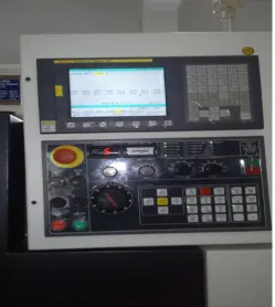
systems. i. Operating system software ii. Machine interfaced [image:2.595.36.286.217.496.2]software and iii. Application software. There are many benefits CNC. i. The part program and tape reader are used only once to enter the program into the computer memory ii. Tape editing at the machine site iii. Metric conversion iv. Greater flexibility v. User written programs, and vi. Total manufacturing system. Machine control Unit of the CNC lathe is shown in Fig. 2.1.
Fig. 2.1. Machine control Unit of the CNC lathe.
II. Cutting Tools, Equipment and Machines:
2. 1.
In the present experimental work, CNC lathe is Ace Micromatic Jober XL, Bangalore make, Igloo Model. Tungsten Carbide single point cutting tools are used in turning operation on CNC lathe. Hydraulic 3- jaw chuck, Tail stock and tool head of CNC lathe are shown in Fig. 2.2Fig.2.2: Tail stock and 8 station indexable tool head of CNC lathe.
2.2 Work piece:
[image:2.595.311.547.242.368.2]A batch consisting of 6 nos Mild Steel work pieces are specially fabricated in the experiments on CNC lathe. The cylindrical work piece is shown in Fig. 2.21. The operations include facing, plain turning, chamfering and parting off operations.
Fig. 2.21 Cylindrical Mild Steel work piece.
III. EXPERIMENTAL SET UP:
[image:2.595.309.530.540.719.2]The experimental set up on CNC Lathe is shown in Fig. 3.1. Tungsten Carbide single point cutting tools are used in the turning operation on C N C Lathe. Various parts are shown below: 1. Hydraulic chuck. 2. Mild steel work piece. 3. Tungsten Carbide cutting tool. 4. Input power to the Dynamometer. 5. Strain reader. 6. Dynamometer.
© 2016, IRJET | Impact Factor value: 4.45 | ISO 9001:2008 Certified Journal
| Page 2959
IV. RESULTS AND DISCUSSIONS:
4.1 Experiments on CNC Lathe:
[image:3.595.40.275.268.403.2]Mild Steel round bar stock of 20 mm diameter is used as workpiece in the present experiments. The work piece is loaded into the hydraulic chuck of CNC Lathe. CNC part program is written and it is executed at spindle speed N = 400 rpm and the corresponding cutting speed, v = (¶ D N / 1000) m/min. = (22 x 19 x 400) / (7 x 1000) = 23.9 m/min. Depth of cut used is 0.30 mm. Cutting conditions for turning operation are shown in Fig. 4.1.
Fig. 4.1. Cutting conditions for turning operation.
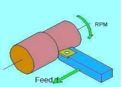
Feed is the term applied to the distance the tool bit advances along the work piece for each revolution of the lathe spindle. Feed is measured in mm per revolution. Fig. 4.2 shows the direction of Feed in Lathe.
Fig. 4.2. Direction of Feed in Lathe.
A light feed must be used on slender and small work pieces to avoid damage. In the normal practice, if an irregular finish or chatter marks are developed during turning operation on Lathe, it is necessary to reduce the feed and checking is required for the tool bit for alignment and sharpness. Also, feed plays a vital role in the control of
surface finish on the work pieces. Generally, in the case of final machining of inside of the cylinder liners, external turning of pistons, inside machining of hydraulic cylinders, bush bearings, etc., very better surface finishing is required for the prolonged and long life for the components. Hence, practical experiments are conducted to investigate the effect of variation of Feed rate on the Surface roughness (Ra) on the
work piece on CNC Lathe. Plain turning operation is performed on the 19 mm diameter work piece in CNC Lathe. Three feed rates are selected in the present work : 0.15, 0.30 and 0.45 mm / rev. In the first experiment, the plain turning operation is performed on two specimens on CNC Lathe with 0.15 mm/rev feed rate. The corresponding Surface Roughness value (Ra) is measured with the surface
[image:3.595.308.448.310.477.2]roughness tester, as shown in Fig. 4.3.
Fig. 4.3. Surface Roughness Tester.
The second experiment is performed with plain turning operation on two more specimens on CNC Lathe with 0.30 mm/rev feed rate. The corresponding Surface Roughness value (Ra) is again measured on the two specimens also.
Finally, in the third experiment, plain turning operation is performed on the last two more specimens on CNC Lathe with 0.45 mm/rev feed rate. The corresponding Surface Roughness value (Ra) is again measured on the last two
specimens also. All the six work pieces are shown in Fig. 4.4.
[image:3.595.36.236.505.648.2] [image:3.595.309.559.643.745.2]
© 2016, IRJET | Impact Factor value: 4.45 | ISO 9001:2008 Certified Journal
| Page 2960
The results of the effect of Feed rate on the Surface [image:4.595.37.270.358.471.2]Roughness value on Mild Steel work pieces are is shown in Table 4.1.
Table 4.1: Results of the effect of Feed rate on the Surface Roughness value on Mild Steel work pieces.
S. No. Feed Rate mm/ rev Surface Roughness (Ra) µm
1 0.15 1.36
2 0.30 1.63
3 0.45 1.95
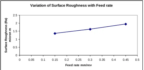
A graph is drawn for the effect of Feed rate on the Surface Roughness value on Mild Steel work pieces in CNC Lathe, as shown in Fig. 4.5.
Variation of Surface Roughness with Feed rate
0 0.5 1 1.5 2 2.5
0 0.05 0.1 0.15 0.2 0.25 0.3 0.35 0.4 0.45 0.5
Feed rate mm/rev
S urf a c e R ou gh ne s s ( R a ) m ic ron m
Fig. 4.5 : Graph showing the variation of Feed rate on the Surface Roughness value on Mild Steel work pieces.
It is observed from the graph that, as the feed rate is increased in CNC Lathe, the surface roughness value is found to increase. In the turning process, as the work piece rotates, the path of the tool will be along a helical pattern. There is a small ridge portion left uncut during the turning process, as the tool bit feeds on the work piece, and moves near the head stock. In the case of minimum or low values of feed rates, this results in minimum material left over on the finished surface and hence this is the reason for a better surface finish value on the work piece. On the other hand, if the feed rate selected on the Lathe is more, the surface roughness value obtained will be more. In practice, it is required to know both the amplitude and frequency to ensure that a surface is fit for a purpose. Also, roughness may promote adhesion. Although a high surface roughness value is undesirable, it can be difficult and expensive to control the feed in manufacturing. Decreasing the roughness of a work piece surface will usually increase its time of
manufacturing and cost of manufacturing. This often results in a trade off between the manufacturing cost and its performance in application.
3. CONCLUSIONS
After conducting the experimental investigation on CNC Lathe with 6 nos. Mild Steel work pieces, the following conclusions are obtained, with the conditions listed above.
1. The Surface Roughness value (Ra) increases with the increase in the Feed rate in CNC Lathe. 2. Mote time will be taken to complete a job with
better surface finish, since the manufacturing on Lathe involves the setting of feed rate at minimum possible value. If the production time is more for one component, cost of production also increases correspondingly.
REFERENCES
[1] N. Satheesh Kumar, Ajay Shetty & Ananth K, “Effect of spindle speed and feed rate on Surface roughness of Carbon Steels in CNC turning”, International Conference on Modelling, Optimization and Computing, Elsevier, Procedia Engineering, Vol. 38, (2012), pp. 691 – 697.
[2] R. Rajamanickam, K. Thanasekaran, G. Prabu & S. Gopal, “Optimization of Surface Roughness for Turning operation in Lathe using Taguchi method”, International Journal of Innovative Research in Science, Engineering & Technology, Vol. 4, Spl. Issue 6, May, 2015, pp. 1668 – 1674.
[3] Nitin Agarwal, “Surface Roughness Modelling with Machining parameters speed, feed & depth of cut in CNC Milling”, M I T Internationsl Journal of Mechanical Engineering, Vol. 2, no. 1, Jan, 2012, pp. 55 – 61.
[4] Suresh Dhiman, Rakesh Sehgal, S. K. Sharma & Vishal S. Sharma, “Machining behaviour of AISI 1018 Steel during turning”, Journal of Scientific & Industrial Research, Vol. 67, May, 2008, pp. 355- 360.
[5] Mikell P. Groover, “Automation, Production Systems, and Computer- Integrated manufacturing”, 3rd Edition, Prentice Hall of India, 2013.
© 2016, IRJET | Impact Factor value: 4.45 | ISO 9001:2008 Certified Journal
| Page 2961
[7] Yoram Koren, “Computer Control of ManufacturingSystems”, Mc Graw Hill International Edition, Singapore, 2014.
BIOGRAPHIES
Sri J. N. Malleswara Rao is working as Associate Professor in the department of Mechanical Engineering at V. R. Siddhartha Engineering College, Vijayawada, A. P. He is having 26 years of Teaching experience. He has guided 12 M. Tech. Project works. His areas of interest are: Machine Tools and Metal Cutting, Roller Burnishing, C N C Machines, & Rapid Prototyping.
Smt. M. Sumalatha is working as Assistant Professor in the department of Mechanical Engineering at V. R. Siddhartha Engineering College, Vijayawada. She is having 10 years Teaching experience. She guided 5 M. Tech. Project works. Her areas of interest are: CNC, CAD/ CAM, Maintenance of Industrial Equip-ment & Additive Manufacturing.
Dr. V. V. S. Kesava Rao is working as Professor in the department of Mechanical Engineering at Andhra University College of Engineering, Visakhapatnam, A. P. ayawada. He is having 4 years of experience as Maintenance Engineer at SAIL. He is having 14 years of Teaching experience. He has guided 40 M. Tech. Project works and 4 Ph. D. scholars. His areas of interest are: Industrial Management, Mainte-nance of Industrial Equipment, & Rapid Prototyping.
Smt. V. Anurupa is working as Assistant Professor in the department of Mechancial Engineering at V. R. Siddhartha Engineering College, Vijayawada. She is having 3 years Teaching experience. Her areas of interest are: CNC, CAD/ CAM, & Additive Manufacturing.