Article 1
Construction and Experimental Study of a 3-Dof
2Haptic Master for Interactive Operation
3Huijun Li *, Aiguo Song, Baoguo Xu, Bowei Li, Hong Zeng andZhen Lin 4
School of Instrument Science and Engineering, Southeast University, Nanjing 210096, China; 5
7
* Correspondence: [email protected]; Tel.: +86-025-8379-3293 8
Abstract: This paper presents a novel 3-degrees-of-freedom (3-DOF) haptic master with 9
rubber bands for self-resetting. The mechanical design avoids coupling between three 10
directions mechanically by using three perpendicular axis intersecting at one point. Bevel 11
gear transmission is adopted to increase the compactness of the overall structure. 12
VR-based interactive system is designed and built by incorporating the proposed haptic 13
master. The proposed haptic device can generate force feedback along 3-degree-of-freedom 14
motion using motors and provide command signals to the avatar in the virtual 15
environment. In order to analyze the performance of the developed device in terms of 16
haptic feedback operation, ergonomics assessments are designed and experimentally 17
implemented. Preliminary studies on the influencing factor including the guidance force, 18
the reset force, the speed of the avatar and the arm the length have been conducted. The 19
results of this paper are of great significance for the design of the haptic master and 20
interactive system. 21
Keywords: haptic master; force feedback; VR-based interaction; ergonomics assessments 22
23
1. Introduction 24
The development of many applications of interactive operation requires flexible haptic master 25
to perform contact tasks. These tasks include interaction with computer aided design models, flight 26
simulators, telerobotic surgery, micro/nano-manipulation, undersea salvage, as well as telerobotic 27
maintenance and decontamination and decommissioning of chemical and nuclear facilities [1,2]. 28
The execution of these tasks by an operator is affected by his/her level of perception of the 29
interaction [3]. This illusion of presence is enhanced by audio, visual and haptic cues. While visual 30
cues are certainly mandatory, and audio cues beneficial at times, haptic cues can significantly 31
improve the flow of information from the environment to the operator for many tasks requiring 32
dexterity [4]. Several types of haptic master devices featuring the feedback function have been 33
proposed, some of which are commercially available devices and some are experimental prototypes 34
[5-7]. The PHANToM, which is the most commonly used haptic device, can generate force feedback 35
along 6-degree-of-freedom (DOF) motions using motors [8]. The Xitack IHP of Xitack SA, which has 36
been proposed for virtual reality applications, has 4-DOF force feedback functions [9]. Dual 37
ArmWork Platform (DAWP) at Argonne National Laboratory [10], one of the key improvements the 38
Cobotic Hand Controller can provide to DAWP operation is the implementation of virtual surfaces, 39
or virtual constraints on motion, as suggested by Faulring [11]. Such master devices can reproduce 40
the constraints or guidance of the slave site and can vastly simplify execution of a contact task. While 41
guidance or constraints can be implemented at the slave side in the existing system, an active master 42
allows for the reproduction of these guidance or constraints at the master and may reduce operator 43
fatigue while increasing efficiency by eliminating unneeded or wrong motions in workspace. Thus, 44
if the operator is inserting a peg into a hole and constrains the motion of the peg to the plane of the 45
objects at the slave but guides it to the top of the hole, he/she feels these same constraints and 46
guidance at the master. 47
There are mainly three kinds of haptic masters. CyberGrasp is typical force feedback gloves 48
which are in form of external skeleton and can make people feel the interactive force by exerting 49
forces on the fingertips according to the degree of stretch of the joints of the fingers [12]. The arm 50
force feedback device can provide force feedback to the operators at multiple degrees of freedom. 51
Such devices have large load structures, with multiple degrees of freedom, allowing complex 52
movement. The typical device of this kind is Omni produced by Sensable Technologies. The body 53
force feedback devices are generally large and complex that not only support the movement of the 54
upper limbs, but also provide a wide range of movements of the lower limbs including the hip, knee 55
and ankle joints, so the device is generally in the form of the outer skeleton. The typical device of this 56
kind is Haptic Walker [13]. 57
Current trend in mechanical design of haptic masters is to meet the need for designs with 58
safety, high performance, sufficient workspace, enough force and torque, high stiffness, and small 59
inertia [14-16]. By their nature, haptic masters operate in contact with a human operator. Greater 60
research effort on the operator’s perception and overall performance using the haptic masters could 61
accelerate the development of haptic interaction technology [17-19]. In these research, the haptic 62
perception of the users was optimized and evaluated using haptic devices. Human factors as well as 63
others that affect the design specifications of force-reflecting haptic interfaces were also concerned 64
[20]. 65
Although a number of commercial and research haptic masters are becoming available, their 66
applications have been limited. Large improvements on existing devices can only be achieved by a 67
proper match between the performance of the device and human haptic abilities. The hope that the 68
generating synthesized haptic experiences is adequate for a particular task. To find out how the 69
users can complete the operation with a haptic master by creating synthetic haptic experiences, 70
quantitative human studies are essential. To determine the nature of these approximations, or, in 71
other words, to find out what we can get away with in creating synthetic haptic experiences, 72
ergonomics studies are essential. Understanding of such influencing factors as the guidance force, 73
the reset force, the speed of the virtual avatar and the arm length is critical for proper design 74
specification of the hardware and software of haptic interfaces. 75
In this paper we introduced a novel 3-degrees-of-freedom (3-DOF) haptic device with self 76
–resetting rubber bands and concerned with quantitative measures of influencing factors that affect 77
the overall performance and then the design specifications of force-reflecting haptic master. The 78
remainder of the paper is organized as follows. Mechanical design and kinematical analysis is 79
presented in Section 2. VR-based interactive system is analyzed in Section 3. Experimental setting is 80
presented in Section 4, and the performance of the proposed system is verified experimentally in 81
Section 5. The paper is then concluded in Section 6. 82
2. Three-DOF Haptic Master 83
2.1. Mechanical Design 84
Mechanical design of haptic masters is to meet the need for designs with sufficient workspace, 85
enough force and torque, high stiffness, small inertia and mechanical singularity. However, some of 86
these requirements, such as large stiffness and small inertia, are conflicting in nature [21, 22]. Due to 87
the multi-criteria and multi-domain functional and performance requirements of high-performing 88
haptic devices, it is not sufficient to develop such a device by sub-optimizing the requirements from 89
each separate discipline. The main design objectives of our device are to obtain a large workspace 90
and mechanical singularity, and, at the same time, provide torque feedback along three motion 91
directions. In this paper, a parallel haptic master for interactive operation is designed consisted of 92
three mutually orthogonal translational axes, which has lower inertia and the better stiffness. At the 93
assembly drawing of this device is presented in Figures 1. Maxon DC motors for each axis are 95
mounted to provide force feedback. The device is capable of rendering continuous forces up to 25N 96
in X and Y axis and torque of 0.5Nm in Z axis. The user grasps a handle mounted on the end effector 97
which is replaceable. 98
99
Figure 1. General assembly drawing of the haptic master (1) Base; (2) Cuboid frame; (3) Handle; (4) 100
Bevel gears; (5) (6) Actuators and photoelectric encoders; (7) Cylinder sleeve 101
The proposed structure is similar to a 3-axis gyroscope in which three axes are orthogonal and 102
intersect at a fixed point that will not change its position while the handle moves or rotates. At the 103
same time, each kinematic singularity is independent and there is no movement intervention which 104
means that coupling is avoided. 105
The device mainly consists of the base, the cuboid frame and cylindrical sleeve, three actuators 106
and photoelectric encoders, a torsion spring for restoration of rotation in Z axis, two rubber bands 107
for self-resetting in X and Y axis, the handle and couplings. The cuboid frame and the cylindrical 108
sleeve are moved in X- and Y-direction through the shaft, and the operating handle is rotated around 109
Z axis by the rotary shaft. 110
to measure the rotation angle in three degrees of freedom 111
Three Maxon encoders are utilized to measure the rotation angles in three degrees of freedom 112
around the motor shafts that are used to calculate the pose of the operating handle, which is 113
coherent with the motion of the operator. Three DC motors manufactured by Maxon Corporation 114
are used to generate the force / torque feedback along X, Y, and Z axis respectively to act on the 115
operator's hand. The forces feedback generated by the actuators on X and Y axis are transferred by 116
two bevel gears to ensure the consistent directions with X and Y axis. While haptic devices usually 117
work a low speed and provide high torque, corresponding reducer are equipped to increase the 118
motor output torque and to reduce the rotational speed. In addition, restoration mechanism is 119
designed to make the haptic device return to the originating pose after operating. In the cylindrical 120
sleeve a torsion spring is installed for rotation restoration around Z axis by placing each end in the 121
position limitation holes which are connected to the actuator and to the handle respectively. While 122
the handle rotates around Z axis, the torsion spring elastic force acts as restoration force. Each end of 123
two rubber bands is fixed at the bottom of the middle actuators and the frame respectively, pulling 124
to each side to realize zero reset in X and Y axis by the elastic forces of the rubber bands. Also 125
buttons are equipped at the end of the handle to implement restoration during movement and to 126
switch the functional mode. Such mechanism design is valuable for high stiffness, small inertia and 127
mechanical singularity and other aspects. The developed haptic device is shown in Figure 2. 128
130
Figure 2. Prototype of the designed 3-DOF haptic master 131
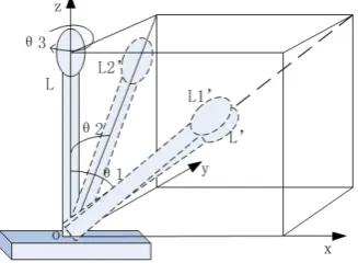
2.2. Kinematics analysis 132
The Kinematic diagram of the designed haptic master is described in Figure 3. The motion of 133
the haptic device to any point in the workspace can be decomposed into motion components on 134
x-o-z plane and y-o-z plane respectively. 135
136
Figure 3. Kinematical Diagram of the Designed Haptic Master 137
Assuming that the length of the handle bar is l and the rotational angles of on x-o-z plane and 138
y-o-z plane are θ1 and θ2 respectively, if the coordinates of the end of the handle are (Px, Py, Pz), the 139
relationship between the position of the end, the rotational angles of the handle and the length of the 140
handle bar l is (ignoring minor deformation of the bar), 141
1
2 2
1 2
1 ( ) ( )
θ
θ θ
× =
+ +
x
l tan P
tan tan
(1) 142
2
2 2
1 2
1 ( ) ( )
θ
θ θ
× =
+ +
y
l tan P
tan tan
(2) 143
2 2
1 2
1 ( θ) ( θ )
=
+ +
z
l P
tan tan
(3) 144
The rotational ranges of the haptic device along X, Y, Z are -60°~60° -
,
60°~60° -90°~90°,
145respectively and the distance from the center of rotation to the end of the handle is 150 mm, so the 146
motion space of the haptic master can be deduced to be a spherical surface from formula (1-3) and its 147
149
150
Figure 4. Working space of the developed haptic master 151
3. VR-Based Force Feedback Interactive System 152
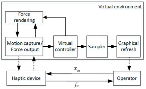
3.1. System Construction 153
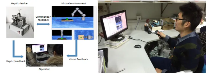
VR-based system consists of the operator, the haptic master, the virtual environment which 154
integrates with the geometric model, the kinematic model, the controller and the force rendering 155
module. Figure 5 shows the schematic diagram of the system. In such a system, the haptic master is 156
utilized to acquire the motion of the operator’s hand and to provide force feedback so that the 157
operator can control the avatar in VR and feel the interactive force between the avatar and the virtual 158
objects. The virtual environment is used to create a digital model of the physical world in the 159
computer and calculate the virtual force according to different operations based on operational 160
kinematics and dynamics of different tasks. The goal of force rendering is to convert the calculated 161
virtual forces to match the capabilities of the virtual force signal with the force-sensing interaction 162
device to ensure stable force feedback. When a human operator operates the haptic master, 163
command (x ) is sent out to the virtual environment to control the avatar and virtual force (f ) is fed 164
back to the operator with graphical refresh at the same time. 165
166
Figure 5. The structure diagram of the VR-based haptic interactive system 167
One of the major goals in this system is to provide the operator with force and visual feedback. 168
The graphic model maintains the information about the current geometric states of the avatar and 169
the environment. Collision detection is conducted while performing tasks in the virtual 170
environment. This allows the virtual objects to deform and give counterforce to the avatar. This force 171
generated in the virtual environment exerts on the operator at the same time. Then the operator 172
holding the haptic master feels the counterforce acting on the avatar and watches the motion of the 173
virtual objects on the screen. The combination of visual and force feedback makes the operator feel 174
In order to improve the frequency of force feedback, the virtual environment module is divided 176
into two loops, one is for visual display and the other is for force feedback. Since the two loops can 177
be processed independently, the virtual force can be rendered at a high frequency of 500~1KHz to 178
ensure the continuity and stable perception for the operator. The graphics update loop is to complete 179
the collision detection, the collision response (including deformation calculation and graphics 180
rendering) at a lower frequency of tens of hertz. 181
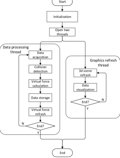
3.2. Software Design 182
The system software provides interface display and visual feedback for the operator. The whole 183
software is developed in Microsoft Visual Studio2008 platform, based on MFC framework and 184
Measurement Studio. OpenGL is used as a graphical interface to render the 3D virtual scene and to 185
complete the dynamic elements loading. The overall flowchart of the software is shown in Figure 6. 186
Start
Open two threads
Data acquisition
Collision detection
Virtual force calculation
Data storage
Virtual force refresh
3d scene refresh
Data visualization
End Initialization
End?
End?
Y
Y
N
N Graphics refresh
thread Data processing
thread
187
Figure 6. Flow chart of the haptic feedback environment 188
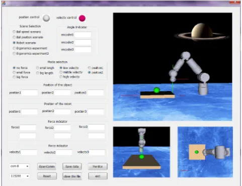
According to the function of each module of the force feedback system, the layout of the whole 189
software is designed in detail. There are several different functional areas in the software interface. 190
The first is serial mode setting area. Serial communication mode is mainly uses in this system. Before 191
opening the serial port, the operator need to set the serial port parameters by pulling down the menu 192
on the serial port baud rate, serial number to choose to improve the software versatility and 193
compatibility. The Operators can also open or turn off the serial port at any time and reset the entire 194
software. The second is data storage area which includes the degree of information on each degree of 195
freedom, the location and speed of the virtual avatar, and the feedback force information of each 196
degree of freedom. In the experimental operation, the operator can click the Save button to save the 197
data in the specified path in a certain format to save as a text document. The third is data 198
visualization area. In order to understand the angle information and feedback force information in 199
the three degrees of freedom and virtual force feedback in dials and waveforms. The fourth is virtual 201
scene selection area. In order to adapt to different operating environment and experimental tasks, 202
three different virtual environments are designed in the software, namely the flexible ball scene 203
model, virtual robotic task scene and ball tracking scene. The operator can switch according to their 204
own needs to operate in the corresponding scenario. The last is operation mode selection area. The 205
haptic master is designed in line with the principles of ergonomic to adapt to the human body arm 206
operating habits and with a suitable elastic reset force to ensure self-resetting. Because the haptic 207
master is similar to the selector or joystick, it can be used for position control or speed control. The 208
operator can quickly switch between the position control mode and the speed control mode in this 209
area. The overall software interface is shown in Figure 7. 210
211
Figure 7. Software Interface of the Force Feedback System 212
3.3. Virtual Force Feedback 213
In the VR-based system, coordinated visual and force feedback can improve the perception of 214
the operator. Generally, the God-Object algorithm can be used to calculate the interactive force 215
between the avatar and the virtual object. According to the single point contact linear dynamic 216
model, when the avatar interacts with the virtual object, the virtual force is, 217
= 0 − < ≥ (4)
218
wherein denotes the interaction force between the avatar and the virtual object, and 219
represent the location of the contact point and the virtual agent point respectively, is the virtual 220
wall stiffness. The feedback force is limited by setting the maximum threshold in the software so that 221
it will not exceed the allowable force range. 222
4. Experiments 223
4.1. Experimental System 224
The haptic master is mainly used in the field of VR-based interaction and teleoperation to 225
acquire the movement of the operator's hand and to provide the operator with force feedback. As 226
man-machine interactive interface, not only mechanical but also ergonomic characters are important. 227
In order to experimentally evaluate the performance of the developed haptic master, we built a 228
prototype of VR-based interactive system for experiments. Several ergonomic experiments are 229
designed and performed. Effective data collected is utilized to statistically analyze the characteristics 230
and efficiency while using the developed haptic master. 231
The experimental system consists of the developed haptic master, the virtual environment and 232
of the virtual environment, such as contact force, frictional force, guidance force, etc., through the 234
haptic master. 235
236
Figure 8. Experimental system 237
4.2. Experimental Tasks 238
In this study, we mainly analyze several factors that play a significant role in the haptic 239
interactive system, including the guidance force, the reset force, the speed of the avatar and the arm 240
length. Ten healthy volunteers aged 20-30 years (habitual use of the right hand) participated in the 241
experiments. The experiments consist of two parts. The first part is the virtual robotic task scenario 242
shown as Figure 9(a). In this task scenario, the operator should control the virtual arm through the 243
haptic device to grasp the green ball on the yellow plane, then move it to the red ball and release. 244
Catching or releasing the ball is switched by the button on the handle of the haptic master. In this 245
experiment, no guidance is provided and the operator should plan their own path according to the 246
information available to them. The second part of the experiment is ball tracking scenario shown in 247
Figure 9 (b). This is a path-guided operational task. The operator should control the blue ball 248
through the haptic master to track the pink ball following the preset path. Once the blue ball touched 249
the pink ball, the latter moved to the next positon and the operator should go on tracking. The entire 250
process consists of six such cycles. 251
252
(a) (b) 253
Figure 9. Experimental Tasks. (a) Virtual robotic scenario; (b) Ball tracking scenario 254
Variable-controlling approach is applied in the experiment to analyze the effects of each factor 255
on the interactive operation. The first factor is the guidance force (fg) provided by the haptic master
256
a1, a2 and a3 respectively. The second factor is the reset force (fr) which drivers the haptic device
258
back to the initial pose. Suppose the reset force of 0N, 2N, 4N is for condition b1, b2 and b3 259
respectively. The third is the speed of the virtual avatar which is set at 0.5cm/s, 1.5cm/s and 2.5cm/s 260
for the condition c1, c2 and c3 respectively. 261
Among all the control factors, a1, b1, c2 are the default control factors. During the experiments, 262
when the influence of a variable is studied, the control factor of this variable is changed, and other 263
variables are the default factors. For example, three groups of experiments at condition 264
、
、
a1*b1*c2 a2*b1*c2 a3*b1*c2 should be carried out to study the effect of the guidance force in the 265
virtual robotic scenario and the ball tracking scenario respectively. So each subject needs to do 18 266
experiments and the experimental sequences of each subject were randomly arranged. 267
5. Results and Analysis 268
5.1. Effects of the Guidance Force 269
Three levels of 0N, 2N, and 4N were applied in the experiment to investigate the influence of 270
the guidance force on the operation efficiency of the haptic interactive system. The elapsed time for 271
completing the designed task was recorded, as is shown in Table 1. 272
Table 1. Average Task Completion Time (Second) 273
Subjects Virtual robotic scenario Ball tracking scenario fg=0N fg =2N fg =4N fg =0N fg =2N fg =4N
1 21.625 18.633 17.846 46.157 40.492 38.491
2 25.648 24.765 22.694 53.719 48.468 46.189
3 16.654 14.369 15.432 66.492 62.483 55.371
4 18.462 16.751 16.345 49.755 44.392 43.034
5 25.349 21.459 21.469 62.449 58.428 55.482
6 28.394 28.200 25.624 55.664 52.983 52.648
7 23.462 21.954 18.694 53.469 52.694 48.691
8 23.489 20.645 19.369 49.648 44.669 45.893
9 19.762 19.239 17.425 51.673 50.945 50.694
10 21.694 20.469 20.964 55.644 52.469 50.442 274
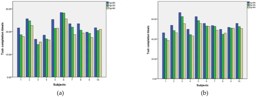
According to the statistical data in Table 1, task completion time histogram of each operator 275
with three levels of guidance force in two scenarios is shown in Figure 10. 276
277
(a) (b) 278
Figure 10. Task completion time histogram in two different scenarios. (a) Virtual robotic scenario; (b) 279
As can be seen from the Figure 10, the overall distribution of task completion time in three cases 281
is consistent although the task completion time of ten subjects is slightly different. The guidance 282
force will shorten the task completion time in both two scenarios. In the case of the virtual robot 283
scenario, task completion time was reduced by 15.3% at most and 8% on average with 2N guidance 284
force compared with no guidance force. When 4N guidance force was available, task completion 285
time was shortened by 20.3% at most and 12.7% on average compared with no guidance force. In the 286
ball tracking scenario, task completion time reduction was 10.77% at most and 6.7% on average with 287
2N guidance force compared with no guidance force. When 4N guide force was available, task 288
completion time was shortened by 16.60% at most and 10.6% on average. The result indicates that 289
the guidance force can give the operator a certain operation hint which can help to improve the 290
operation efficiency and to shorten the task completion time. Although task completion time is 291
averagely shortened with 4N guide force compared with 2N guide force, further experiments should 292
be carried out to study the optimal guidance force for different subjects and different tasks. 293
5.2. Relationship between the Reset Force and the Operating Range 294
To study the effect of the reset force on the interactive operation, the reset force was set at three 295
grades that include elastic force of the rubber bands only, elastic force plus 2N motor output and 296
elastic force plus 4N motor output. Other variables were the default factor. Univariate analysis of 297
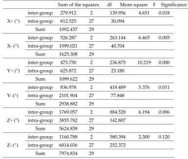
variance was used to analyze. Table 2 shows the result of variance analysis of the maximum 298
operating angle (in degree) in six motion directions. 299
Table 2. Analysis of variance the maximum operating angle in six movement directions 300
Sum of the squares df Mean square F Significance
X+ (°)
inter-group 279.912 2 139.956 4.651 0.018
intra-group 812.525 27 30.094
Sum 1092.437 29
X- (°)
inter-group 526.287 2 263.144 6.465 0.005
intra-group 1099.021 27 40.704
Sum 1625.308 29
Y+ (°)
inter-group 473.750 2 236.875 10.219 0.000
intra-group 625.872 27 23.180
Sum 1099.622 29
Y- (°)
inter-group 836.978 2 418.489 5.376 0.011
intra-group 2101.904 27 77.848
Sum 2938.882 29
Z+ (°)
inter-group 1769.057 2 884.528 6.194 0.006
intra-group 3855.782 27 142.807
Sum 5624.839 29
Z- (°)
inter-group 1160.788 2 580.394 2.300 0.120
intra-group 6814.036 27 252.372
Sum 7974.824 29
X+ means the positive direction of X axis X- means the negative direction of X axis. The rest in the same way.
301
In the result of the variance analysis given in Table 2, the sum of the squared variance, the mean 302
square, the F value and the probability P of the groups are given. From the significance level P <0.05, 303
there was a significant difference in the mean value between groups in the positive and negative 304
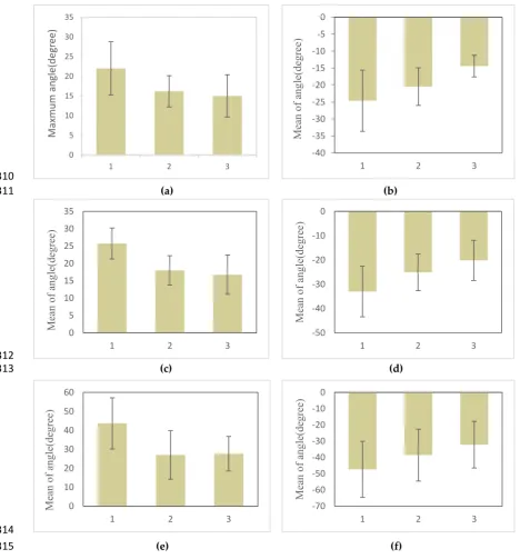
Figure 11 shows the histogram of the range of the movement of the hand in the positive and 306
negative directions of the X, Y, Z under the conditions of three grades of resetting force. The abscissa 307
in Figure 11 is 1, 2, 3, representing the motor reset force of 0N, 2N and 4N respectively and the 308
vertical axis represents the maximum angle of the operating movement in this direction degree (°). 309
310
(a) (b) 311
312
(c) (d) 313
314
(e) (f) 315
Figure 11. Bar charts of the range of motion with three grades of resetting force (95% CI). (a) In the X 316
axis positive direction; (b) In the X axis negative direction; (c) In the Y axis positive direction; (d)In 317
the Y axis negative direction; (e)In the Z axis positive direction; (f)In the Z axis negative direction. 318
As can be seen from the Figure 11, the reset force effects the operating range of the haptic 319
master in all motion directions. The greater the reset force, the corresponding operating range is 320
smaller. This is possibly because the reset force constraints the free motion of the operator to some 321
extent. So the reset force should be minimized in the condition that the restoration is ensured. 322
323 324
0 5 10 15 20 25 30 35
1 2 3
Maxmum angle(degree)
-40 -35 -30 -25 -20 -15 -10 -5 0
1 2 3
Mean of angle(degree)
0 5 10 15 20 25 30 35
1 2 3
Mean of angle(degree) -50
-40 -30 -20 -10 0
1 2 3
Mean of angle(degree)
0 10 20 30 40 50 60
1 2 3
Mean of angle(degree) -70
-60 -50 -40 -30 -20 -10 0
1 2 3
5.3. Relationship between the Speed of the Avatar and the Operating Range 325
In this experiment, the speed of the virtual object is set at 0.5m/s, 1.5m/s, 2.5m/s respectively 326
and the other factors are set as default factors. Three groups of the operable range were recorded in 327
degree (°) and one-way analysis of variance (ANOVA) was used to study the effects of different 328
conditions on the experiments. The results are shown in Table 3. 329
Table 3. Variance Analysis of Virtual Object Motion 330
Sum of the squares df Mean square F Significance
X+ (°)
inter-group 199.247 2 99.624 4.004 0.030
intra-group 671.833 27 24.883
Sum 871.080 29
X- (°)
inter-group 250.083 2 125.041 2.350 0.115
intra-group 1436.942 27 53.220
Sum 1687.025 29
Y+ (°)
inter-group 124.523 2 62.261 2.013 0.153
intra-group 835.071 27 30.929
Sum 959.593 29
Y- (°)
inter-group 354.916 2 177.458 2.142 0.137
intra-group 2236.635 27 82.838
Sum 2591.551 29
Z+ (°)
inter-group 1412.462 2 706.231 4.761 0.017
intra-group 4005.187 27 148.340
Sum 5417.648 29
Z- (°)
inter-group 1083.262 2 541.631 1.721 0.198
intra-group 8496.079 27 314.670
Sum 9579.341 29
It can be seen from the significance level (P) that the intra-group means along X-axis positive 331
direction and Z-axis positive direction are significantly different (P< 0.05) while the differences in 332
other directions are not significant. Furthermore, the differences of the measurement data were 333
compared with the homogeneity test of variances and the results indicated there was no significant 334
difference between the variance of each group at 0.05 level, that is, the variance is homogeneous, as 335
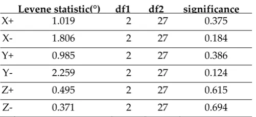
is shown in Table 4. 336
Table 4. Homogeneous test of variance under conditions of different avatar speed 337
Levene statistic(°) df1 df2 significance
X+ 1.019 2 27 0.375
X- 1.806 2 27 0.184
Y+ 0.985 2 27 0.386
Y- 2.259 2 27 0.124
Z+ 0.495 2 27 0.615
Z- 0.371 2 27 0.694
LSD multiple comparison procedure was used for further analysis. In Table 5, the experimental 338
significance level was less than 0.05, there was a significant difference between the two groups. The 340
results show that there is a significant difference in operating range in the six directions when the 341
virtual object moved at the lowest speed and the highest speed, which indicates that the speed of the 342
virtual object has an effect on the amplitude of the haptic device. 343
Table 5. LSD multiple comparison results of experimental data of virtual object velocity 344
Dependent
Variable (I)a (J)a
Mean Difference (I-J)
Standard
Error significance
95% confidence intervals (CIs) lower limit upper limit
X+(°)
1.00 2.00 4.17500 2.23082 0.072 -.4023 8.7523
3.00 6.18800* 2.23082 0.010 1.6107 10.7653
2.00 1.00 -4.17500 2.23082 0.072 -8.7523 .4023
3.00 2.01300 2.23082 0.375 -2.5643 6.5903
3.00 1.00 -6.18800* 2.23082 0.010 -10.7653 -1.6107
2.00 -2.01300 2.23082 0.375 -6.5903 2.5643
X-(°)
1.00 2.00 -3.68900 3.26252 0.268 -10.3831 3.0051
3.00 -7.07000* 3.26252 0.039 -13.7641 -.3759
2.00 1.00 3.68900 3.26252 0.268 -3.0051 10.3831
3.00 -3.38100 3.26252 0.309 -10.0751 3.3131
3.00 1.00 7.07000* 3.26252 0.039 .3759 13.7641
2.00 3.38100 3.26252 .309 -3.3131 10.0751
Y+(°)
1.00 2.00 2.33300 2.48711 .357 -2.7701 7.4361
3.00 4.98700 2.48711 0.055 -.1161 10.0901
2.00 1.00 -2.33300 2.48711 0.357 -7.4361 2.7701
3.00 2.65400 2.48711 0.295 -2.4491 7.7571
3.00 1.00 -4.98700 2.48711 0.055 -10.0901 .1161
2.00 -2.65400 2.48711 0.295 -7.7571 2.4491
Y-(°)
1.00 2.00 -5.47200 4.07034 0.190 -13.8236 2.8796
3.00 -8.28400 4.07034 0.052 -16.6356 .0676
2.00 1.00 5.47200 4.07034 0.190 -2.8796 13.8236
3.00 -2.81200 4.07034 0.496 -11.1636 5.5396
3.00 1.00 8.28400 4.07034 0.052 -.0676 16.6356
2.00 2.81200 4.07034 0.496 -5.5396 11.1636
Z+(°)
1.00 2.00 10.28330 5.44684 0.070 -.8927 21.4593
3.00 16.65510* 5.44684 0.005 5.4791 27.8311
2.00 1.00 -10.28330 5.44684 0.070 -21.4593 .8927
3.00 6.37180 5.44684 0.252 -4.8042 17.5478
3.00 1.00 -16.65510* 5.44684 0.005 -27.8311 -5.4791
2.00 -6.37180 5.44684 0.252 -17.5478 4.8042
Z-(°)
1.00 2.00 -8.10550 7.93309 0.316 -24.3829 8.1719
3.00 -14.69300 7.93309 0.075 -30.9704 1.5844
2.00 1.00 8.10550 7.93309 0.316 -8.1719 24.3829
3.00 1.00 14.69300 7.93309 0.075 -1.5844 30.9704
2.00 6.58750 7.93309 0.414 -9.6899 22.8649
345
Figure 12 shows the histogram of the operating range of the haptic master in the positive and 346
negative directions of X, Y, Z axis under the conditions of three grades of avatar speed. The abscissa 347
in Figure 12 is 1, 2, 3, representing the avatar speed of 0.5cm/s, 1.5cm/s and 2.5cm/s respectively. The 348
vertical axis represents the maximum operating angle in degrees in the corresponding direction. 349
350
(a) (b) 351
352
(c) (d) 353
354
(e) (f) 355
Figure 12. Bar graph of the operating range in six motion directions with three grades of avatar speed. 356
(a)X+; (b)X-; (c)Y+; (d)Y-; (e)Z+; (f)Z- 357
It can be seen from Figure 12 that of the moving speed of the virtual avatar has a certain 358
influence on the operating range in each direction. The larger the moving speed, the smaller the 359
operating range in the corresponding motion direction. 360
361
0 5 10 15 20 25 30
1 2 3
Mean value(Degree)
-40 -35 -30 -25 -20 -15 -10 -5 0
1 2 3
Mean value(Degree)
0 5 10 15 20 25 30 35
1 2 3
Mean value(Degree)
-50 -40 -30 -20 -10 0
1 2 3
Mean value(Degree)
0 10 20 30 40 50 60
1 2 3
Mean value(Degree)
-70 -60 -50 -40 -30 -20 -10 0
1 2 3
5.4. Relationship between the Arm Length and the Operating Range 362
In the experiment, the length of the right arm (the distance from the scapula to the palm) of each 363
subject was measured. Figure 13 shows the scatter plot of the relationship between the operating 364
range and the arm length. The abscissa is the arm length and the ordinate is the average operating 365
range of multiple experiments. 366
367
Figure 13. The scatter plot of the relationship between the operating range and the arm length 368
Method of correlation analysis was applied to study the relevance. In this paper, the spearman 369
correlation coefficient was used to analyze the relationship between the arm length and the 370
operating range. The results are shown in Table 6. 371
Table 6. Operation space range and arm length correlation coefficient table 372
Spearman rank correlation coefficient
X+ (°) X-(°) Y+(°) Y-(°) Z+(°) Z-(°)
Arm length (cm)
correlation coefficient 0.638 -0.413 0.675 -0.122 0.626 0.371
Sig.( double sides) 0.047 0.235 0.032 0.783 0.053 0.291
N 10 10 10 10 10 10
From the Table 6, the operating range correlates with the arm length in the X-axis Y-axis 373
positive direction at 0.05 significant level. Because the X-axis positive direction is to move the handle 374
of the haptic device to right and the Y-axis positive direction is to move forward, it can be deduced 375
that the operating range and the arm length are positively correlated when the handle is moved 376
away from the body and the correlation coefficients are 0.638 and 0.655 respectively. 377
5.5. Differences in Operating Range along Different Directions 378
Table 7 shows the operating ranges of the experimenter in each direction in each experiment, ie, 379
the maximum operating angle. 380
Table 7. Operating range statistics 381
X+(°) X-(°) Y+(°) Y-(°) Z+(°) Z-(°)
Speed of virtual object
Slow 21.709 -24.406 25.479 -33.013 41.948 -47.341
Medium 17.534 -20.717 23.146 -27.541 31.665 -39.235
Fast 15.521 -17.336 20.492 -24.729 25.293 -32.648
Reset force
Small 22.002 -24.606 25.742 -32.987 43.648 -47.347
Fast 16.194 -20.453 18.010 -25.108 27.031 -38.595
Large 15.013 -14.405 16.755 -20.160 27.707 -32.169 -100
-80 -60 -40 -20 0 20 40 60 80
40 50 60 70 80
Operat
ing
range
/
Degree
Arm length/cm
z-As can be seen from Table 7, the maximum range along X and Y negative direction is greater 382
than that along the positive direction. X negative direction represents moving the handle to the left 383
and positive direction represents moving the handle to the right. Similarly, Y negative direction 384
represents moving the handle close to the operator and the positive direction represents moving the 385
handle away from the operator. It can be concluded that the motion of the operator's handle toward 386
himself/herself is greater than moving away from himself/herself. This means that asymmetric 387
control interval is necessary for a haptic-master based system. 388
5.6. Determination of Operating Range and Operation Speed 389
Three sets of experiments were taken to study the operating range of the haptic master while 390
the moving speed of the virtual object was controlled at the medium speed, reset force is provided 391
by the rubber bands. According to Table 7 we can obtain that under the above conditions the average 392
range of hand movement is roughly -21.96 ° ~ 19.74 ° along X-axis angle, -29.25 ° to 24.95 ° along Y 393
and -41.60 ° to 39.09 ° around Z axis. 394
The distance from the end of the handle to the intersection of three axes is about 30cm, so the 395
magnitude of the swing from left to right is about -11.49cm ~ 10.33cm, the magnitude of the swing 396
forwards or backwards is about -15.32cm ~ 13.06cm, and the wrist rotation angle range is -41.60 ° ~ 397
39.09 °. 398
In the experiment, the speed at which the operator operates the handle is recorded at the same 399
time, so the maximum operating speed of the operator can be obtained by the above method. Table 8 400
shows the operating speed of the subjects in each direction in experiments, in degrees per second. 401
Table 8. Operation speed data statistics 402
Direction X+(°/s) X-(°/s) Y+(°/s) Y-(°/s) Z+(°/s) Z-(°/s)
Speed of virtual object
Slow 102.333 -111.000 101.999 -103.666 381.943 -347.221
Medium 83.333 -113.333 76.333 -100.333 280.555 -305.555
Fast 89.524 -108.095 71.428 -76.666 255.952 -259.920
Reset force
Small 99.333 -101.666 104.332 -101.999 387.499 -348.610
Fast 98.000 -106.333 90.333 -112.333 255.555 -312.500
Large 110.000 -110.476 104.761 -89.523 261.904 -287.698
Since the moving speed and the reset force of the virtual avatar have no significant effect on the 403
operating speed, all the experimental results are averaged and the maximum operating speed in 404
different directions can be obtained. The operating speed in X, Y, Z axis is -109.18°/s ~ 98.38°/s, 405
-99.73°/s ~ 92.06°/s, -310.60°/s ~ 300.75°/s respectively. Converted the speed to translation in the 406
workspace, the operating speed from left to right is -57.17cm/s ~ 51.51cm/s, the operating speed 407
forwards and backwards is -52.22cm/s ~ 48.20cm/s. That is, the operators are used to operating the 408
haptic master at such speed and this should be considered while an interactive system is designed 409
using a haptic master. 410
6. Conclusion 411
In this study, a novel 3-DOF self-resetting haptic device was designed. The mechanical design 412
avoids coupling between three directions mechanically by using three perpendicular axis 413
intersecting at one point. It can provide three DOF force feedback to human operators. VR-based 414
interactive system using the developed device was built and experiments were conducted. Statistical 415
analysis was used to study the influencing factor including the guiding force, the reset force, the 416
speed of the virtual object and arm length. The experimental results can provide evidence for how to 417
design and optimize the haptic master and the haptic interactive system. 418
Acknowledgments: This paper is supported by Natural Science Foundation of China under Grants number 420
61403080 and the National Key Research and Development Program of China (No. 2016YFB1001301). 421
Author Contributions: Each co-author made important contributions to this research. Huijun Li organized the 422
research. Aiguo Song and Bowei Li joined in the design of the haptic device and conducted calibration 423
experiments. Zhen Lin, Baoguo Xu and Hong Zeng participated in the formulation of main design targets. This 424
writing was finished by Huijun Li and supervised by Aiguo Song. All authors approved the final version of this 425
paper. 426
Conflicts of Interest: The authors declare no conflict of interest. 427
References 428
1. Bolopion A, Régnier S. A review of haptic feedback teleoperation systems for micromanipulation and 429
microassembly[J]. IEEE Transactions on automation science and engineering, 2013, 10(3): 496-502. 430
2. Sasaki T, Kokubo K, Sakai H. Hydraulically driven joint for a force feedback manipulator[J]. Precision 431
Engineering, 2017, 47: 445-451. 432
3. Pacchierotti C, Meli L, Chinello F, et al. Cutaneous haptic feedback to ensure the stability of robotic 433
teleoperation systems[J]. The International Journal of Robotics Research, 2015, 34(14): 1773-1787. 434
4. Oscari F, Oboe R, Daud Albasini O A, et al. Design and Construction of a Bilateral Haptic System for the 435
Remote Assessment of the Stiffness and Range of Motion of the Hand[J]. Sensors, 2016, 16(10): 1633. 436
5. Laycock S D, Day A M. Recent developments and applications of haptic devices[C], Computer Graphics 437
Forum. Blackwell Publishing, Inc, 2003, 22(2): 117-132.. 438
6. Borro D, Savall J, Amundarain A, et al. A large haptic device for aircraft engine maintainability [J]. IEEE 439
Computer Graphics & Applications, 2004, 24(6):70 - 74. 440
7. Adams R J, Moreyra M R, Hannaford B. Excalibur, A Three-Axis Force Display[J]. Proc of the Asme 441
Winter Annual Meeting Haptics Symposium, 2010. 442
8. Çavuşoğlu M C, Feygin D, Tendick F. A critical study of the mechanical and electrical properties of the 443
phantom haptic interface and improvements for highperformance control[J]. Presence: Teleoperators and 444
Virtual Environments, 2002, 11(6): 555-568. 445
9. Xitact Medical Simulation, http://www.xitact.com 446
10. Noakes, M., Love, L., and Lloyd, P. 2002. Telerobotic planning and control for DOE D&D operations. IEEE 447
International Conference on Robotics and Automation, Washington DC, pp. 3485–3492. 448
11. Faulring E L, Colgate J E, Peshkin M A. The cobotic hand controller: design, control and performance of a 449
novel haptic display[J]. The International Journal of Robotics Research, 2006, 25(11): 1099-1119. 450
12. Bouzit M, Popescu G, Burdea G, et al. The Rutgers Master II-ND force feedback glove[C]. Haptic Interfaces 451
for Virtual Environment and Teleoperator Systems, 2002. HAPTICS 2002. Proceedings. 10th Symposium 452
on. IEEE, 2002:145-152. 453
13. Schmidt H. HapticWalker-A novel haptic device for walking simulation[C]//Proc. of'EuroHaptics. 2004. 454
14. He X J, Choi K S. Safety control for impedance haptic interfaces[J]. Multimedia Tools and Applications, 455
2016, 75(23): 15795-15819. 456
15. Sun X, Andersson K, Sellgren U, Towards a Methodology for Multidisciplinary Design Optimization, 457
Proceedings of the ASME 2015 International Design Engineering Technical Conferences & Computers and 458
Information in Engineering Conference IDETC/CIE 2015, August 2-5, 2015, Boston, Massachusetts, USA. 459
16. Qin H, Song A, Liu Y, et al. Design and calibration of a new 6 DOF haptic device[J]. Sensors, 2015, 15(12): 460
31293-31313. 461
17. Sauvet B, Laliberte T, Gosselin C. Design, analysis and experimental validation of an ungrounded haptic 462
interface using a piezoelectric actuator[J]. Mechatronics, 2017, 45: 100-109. 463
18. Sarakoglou I, Garcia-Hernandez N, Tsagarakis N G, et al. A high performance tactile feedback display and 464
its integration in teleoperation[J]. IEEE Transactions on Haptics, 2012, 5(3): 252-263. 465
19. Sun X, Sellgren U, Andersson K. Situated Design Optimization of Haptic Devices[J]. Procedia CIRP, 2016, 466
50: 293-298. 467
20. Tan H Z, Srinivasan M A, Eberman B, et al. Human factors for the design of force-reflecting haptic 468
interfaces[J]. Dynamic Systems and Control, 1994, 55(1): 353-359. 469
21. Ellis, R.; Ismaeil, O.; Lipsett, M. Design and evaluation of a high-performance haptic interface. Robotica, 472
1996, 14, 321–327. 473
22. Yoon W K, Suehiro T, Tsumaki Y, et al. A method for analyzing parallel mechanism stiffness including 474
elastic deformations in the structure[C].Intelligent Robots and Systems, 2002. IEEE/RSJ International 475