Detection and Imaging of Damage and Defects in Fiber-Reinforced Composites by 3D Computed Tomography Resonance Magnetic Technique
Tarpani A.C.S.P.1., Alves C.L.1, Tannús A.2, Tarpani J.R.1,*
1 Materials Engineering Department, Engineering School of São Carlos, University of São
Paulo, 13590-566, São Carlos-SP, Brazil
2 Physics and Informatics Department, Physics Institute of São Carlos, University of São
Paulo, 13590-566, São Carlos-SP, Brazil
Tarpani A.C.S.P.: [email protected] Alves C.L.: [email protected] Tannús A.: [email protected]
* Corresponding author: [email protected] (http://orcid.org/0000-0003-1201-8999)
Abstract: Damaged and defective fiber-reinforced polymer composites were inspected by magnetic resonance imaging. Nondestructive examination was conducted with samples immersed in saline water solution simulating biofluids permanently in contact with load-bearing orthopedic implants. Size, geometry, orientation and positioning of translaminar and delamination fractures in the test pieces were characterized. In this regard, translaminar damages required all primary imaging planes, namely, axial, coronal and sagittal to be fully portrayed, whereas only sagittal slicing was demanded for entire depiction of delaminations. Size and spatial distribution of water clusters formed in composite samples, as well as surface finishing features of the specimens were also outlined. The evaluated imaging technique has shown high potential for nondestructive inspection of fiber-reinforced polymer parts operating in liquid proton-rich media.
Keywords: Damage and defect assessment; Magnetic resonance imaging; Polymer matrix composite.
Nomenclature
A Axial
C Carbon or Coronal
CF(RP) Carbon fiber (-reinforced polymer) dgd Damage growth direction
EMI Electromagnetic interference EPX-GF Epoxy resin-glass fiber EPX-CF Epoxy resin-carbon fiber FLASH Fast low angle shot
FOV Field of view
FRP Fiber-reinforced polymer
G Glass
GF(RP) Glass fiber (-reinforced polymer)
l Specimen length
(CT)MRI (Computed tomography) Magnetic resonance imaging PEEK Polyetheretherketone
PPS-CF Polyphenylene sulfide-carbon fiber
RARE Rapid image acquisition with refocused echoes
S Sagittal
t Specimen thickness
w Specimen width
2D Two-dimensional
1. Introduction
Compared to structural metallic alloys, high-performance fiber-reinforced polymer (FRP) composites exhibit very low density, high specific stiffness and high specific strength (per unit mass), low probability of catastrophic fracture, corrosion resistance and remarkable design flexibility. They are employed in several engineering fields and, therefore, they operate in high-demanding mechanical, thermal and environmental condition [1].
Increased life expectancy of the human population and the number of victims of traumatic incidents has boosted the need for advanced materials for implants capable of directing, complementing or replacing the functionality of human living tissues, especially for load-bearing (orthopedic) deals. FRP composites have been widely accepted due to their remarkable versatility for orthopedic applications, allowing for matching the biomechanical requirements (e.g. stiffness) necessary for long-term periprosthetic implantation. Biocompatibility of FRP also provides support to the appropriate cellular activity, assisting the regeneration of soft and hard tissues [2-5].
Permanently and temporarily implanted FRP devices in hard tissue applications include full hip joint, knee, ankle, toe, shoulder, elbow, wrist and finger, besides intramedullary spine fusion cage, internal plate for bone fracture repair, cervical, lumbar and femur nails. Excellent reviews on composite materials in orthopedic implants can be found elsewhere [6-18]. Human body implants have a finite lifespan, typically following long-term use, i.e. fatigue, in continuous contact with body fluids. However, implants can move, damage, fracture and therefore stop working properly much earlier than expected [19-30]. In any case, nondestructive, noninvasive, painless, reliable, non-lethal radiation, fast and high penetrating power techniques for determining the degree of structural integrity of advanced FRP orthopedic implants are highly desirable. Multiple examinations with no risk to the patient health would then be feasible to postpone and even avoid surgeries to replace the implanted element (i.e., in-service lifetime extension), and provide surgeon guidance towards the best surgical strategy well before eventual medical procedure [31].
Modern computed tomography magnetic resonance imaging (CT-MRI [33,34]) presents clear advantages over traditional concurrent techniques due to its non-health-threatening nature (against X-ray radiography and eddy current [35,36]), independence on damage orientation (as opposite to ultrasonics [37]), unrestricted use with electrically (carbon fiber-CF) and non-electrically (glass fiber-GF) conductive FRP composites (again contrary to eddy current [36]) and high penetration power of electromagnetic field (differently from the surface-confined analysis provided by thermography [38]).
Furthermore, since body fluids are proton-rich compound and quite sensitive to the magnetic resonance effect, CT-MRI technique is naturally a very promising tool for structural integrity assessments of FRP implants [39-43,48-50].
Though the medical literature provides some in-vivo magnetic resonance images of implanted FRP orthopedic devices [12,44-46], none of the articles addressed the potentialities of MRI to detect and characterize defects and damages. Also, to the best of the authors knowledge, no in-vitro experiment on this subject has already been conducted and published in the open literature.
Recently, the authors conducted MRI experiments with contaminated and damaged aircraft honeycomb sandwich panels, when entrapped hydrogen-rich liquids and crushed core cells were identified, quantified and discriminated [47]. Following that successful initiative, the present study evaluates the potential of multi-slice 3D-MRI technique for in-vitro nondestructive inspection of FRP specimens deliberately damaged under well-controlled conditions and subsequently immersed in saline solution.
2. Composite laminates and test coupons
2.1 FRP laminates
(Fibertex™-Brazil, areal weight of 200 g/m ) stacked array [0/90]10S. The 3.5 mm-thick laminate was
cured in furnace at 70ºC and exhibited fiber volume fraction of 40% and 7% of void content; (ii) continuous carbon fiber-reinforced thermosetting epoxy resin (EPX-CF) laminate obtained at industrial-scale via vacuum bag autoclave processing 24 layers of 0/90 bidirectional plain-weave fiber fabric (areal weight of 193 g/m2) previously impregnated with
high performance aeronautical grade EPX system (Araldite LY 5052 resin and Aradur 5052 polyamines mixture by Huntsman™) piled up to [(0/90)/±452/(0/90)]6 architecture. The 5
mm-thick aerospace grade laminate (like Ref. 2) was cured at 180ºC and presented nominal fiber volume fraction of 60%; (iii) continuous carbon fiber-reinforced thermoplastic polyphenylene sulfide (PPS-CF) laminate manufactured at industrial-scale by hot compressing (300°C) 16 layers of 0/90 bidirectional 5-harness satin (5HS) CF fabric (areal weight of 280 g/m2) semi-impregnated (semi-preg) with aeronautical grade thermoplastic
polyphenylene sulfide stacked to [(0/90)/±452/(0/90)]4 array. The 5 mm-thick aerospace
grade laminate displayed nominal fiber volume fraction of 50%.
It is worth mentioning that the use of carbon and glass FRP fiber-reinforced epoxy composites in biomedical engineering suffered backlash due to concerns about leachable toxic rest monomers of epoxy resins, though initiatives to reduce their risk to human health by promoting higher crosslinking densities have more recently been implemented [17,51-54]. Anyways, one must consider that 1980s carbon and glass FRP implants are still in service [55,56] and deserve to be a matter of interest for in-vivo nondestructive examination. Regarding polyaromatic thermoplastic polymer PPS, it exhibits superior cytocompatibility and in-vivo osteogenesis for novel orthopedic implants, besides elastic modulus practically identical to human cortical bones and lower water absorption [57,58]. Thus, this material will rival ing with widely employed polyetheretherketone (PEEK) [6,8,10,59].
2.2 Purposely damaged test specimens
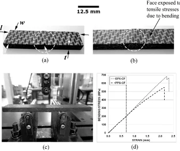
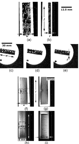
specimens were partially fractured in translaminar (Fig.1-a) and delamination (Fig.1-b) modes in a three-point bending (3PB) setup (Fig.1-c). A notch was machined in translaminar test coupons (arrowed in Fig.1-a) to favor subsequent fracture by flexural loading. All specimens were loaded in bending until their central line deflection attained 1.5 mm (Fig.1-d). This value is substantially lower than that necessary to completely fracture a femur neck in laboratory experiments simulating sideways fall-on-the hip position [60]. This means that a composite orthopedic implanted device can be damaged in relatively common daily events, while the corresponding bone structure remains intact. Once the EPX-CF and PPS-CF specimens where intentionally damaged, they were immersed in water-based saline solution. Regarding the EPX-GF test coupons, no mechanical damage was imposed prior to immersion in saline solution, since only their hygroscopic behavior was of interest during MRI inspection due to its high-volume fraction of voids, i.e. defects.
3. MRI equipment and protocols
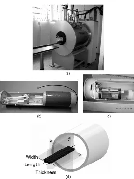
Horizontal 2.0 Tesla superconducting magnet (Oxford Instruments model 85310HR™), operating at 85 MHz, with 310 mm of internal diameter and equipped with a set of high-speed X, Y and Z gradient coils was used (Fig.2). Gradient coils operated with efficiency of 0.16 Gauss/(cm.Ampere), producing magnetic field gradients of about 30 Gauss/cm in a settling time of 160 microseconds. The MRI system operated with Bruker Biospin™ electronics and Paravision™ V console, employing the following protocols for image generation: 2D-RARE (two-dimensional Rapid Image Acquisition with Refocused Echoes), commercially known as Turbo Spin Echo, and 2D-FLASH (two-dimensional Fast Low-Angle Shot).
2D-RARE and 2D-FLASH protocols used in this study enabled the acquisition of two-dimensional images composed of pixels. The third dimension was explored by stacking parallel slices, with slice direction field of view (FOV) determined by the interslice distance and number of slices, which were controlled by the operator.
RARE is a rapid imaging technique that speeds up image acquisition by acquiring more than one k-space (i.e. array of numbers in the form of matrix representing spatial frequencies in resonance imaging) line per repetition (i.e. number of times that each excitation step is reproduced). RARE-type sequence comprises multiple π pulses to create many echoes. By applying a different phase encoding gradient to each echo, multiple k-space lines can be collected in each excitation step. The speed up factor is often referred to as the echo train length, or turbo factor.
FLASH is the first version of a large family of fast gradient-echo methods. It is based on the application of reduced flip angles for MR excitation, the acquisition of magnetic field gradient echoes and considerably shortened repetition times. It is one instance of the generic form of steady-state free precession imaging.
by the MRI device was 0.1x0.1 mm /pixel, although higher levels of resolution of up to 0.05x0.02 mm2/pixel were eventually achieved.
Figure 2. (a) Employed MRI system, (b) empty case of radiofrequency wireless transceiver antenna, (c) falcon tube containing a composite test coupon ready for examination, (d) schematic of experimental MRI setup portraying principal inspected planes for a tablet-shape specimen, namely, A (Axial), S (Sagittal), C (Coronal).
4. Experimental methodologies
4.1 Electrical conductivity measurements
used to determine whether the three composite laminates were prone to this detrimental effect. Electrical resistance of dry specimens was measured according to the four-point probe method [62], which is applicable when the distance between the probes is small compared to the specimen size. Probes were located 5 mm away from each other. Resistivity was calculated using the resistance data and geometry of the specimens.
4.2 Immersion in proton-rich liquid environment
Fractured and defective FRP test coupons were immersed in water-based salt solution simulating biofluids [63]. After 25 days, the purposely damaged EPX-CF and PPS-CF specimens were transferred, along with the undamaged, but defective EPX-GF sample to falcon tubes filled with the same saline solution and then inspected by MRI.
Water absorption curves were obtained for the three laminates up to 110 days of immersion.
4.3 MRI scanning
4.3.1 Electromagnetic interference (EMI)
Figure 3. Mini-vessels utilized for detection of MRI artifacts.
4.3.2 Damaged and defective specimens
Test specimens individually inserted in 50 ml plastic falcon tubes containing saline solution were loaded to the superconducting magnet (Fig.2a-c). The longitudinal axes of the rectangular specimens and cylindrical magnet were aligned parallel to one another. It was also ensured that one of the main (largest) faces of the test coupons would face upward (Fig.2-d).
2D-RARE and 2D-FLASH protocols for images generation were used, and preference was given for the best image quality if time expenditure in both setup and imaging steps were not compromised, which means fractions of an hour for the entire procedure.
Exceptions were long-lasting MRI inspections (up to hundreds of minutes) for highly detailed surface finish analysis.
5. Results and discussion
5.1 Electrical conductivity measurements
Electrical conductivities of EPX-CF and PPS-CF were, respectively, 1.7 E3 Ω.m-1 and 3.0
5.2 Immersion in proton-rich liquid environment
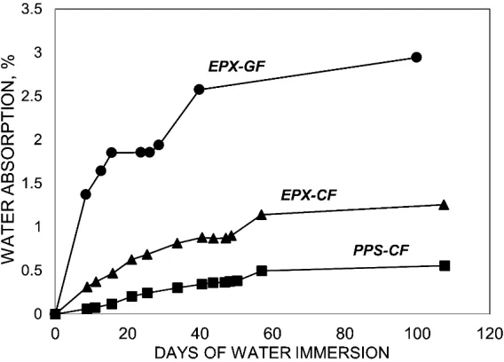
Figure 4 displays water uptake plots for the three composite laminates tested. As expected, the EPX-GF laminate exhibited by far the most hydrophilic behavior, followed by EPX-CF and PPS-CF composites, respectively. Sood & Pecht [64] concluded that water ingress in glass fiber-reinforced composites mainly occur through the fiber-matrix interface due to hydrolysis of the silane glass finish, or from residual thermal stresses. According to the authors, once a path is formed, an aqueous layer can develop through the adsorption, absorption, and capillary action of moisture at that region.
Regarding the CFRP laminates, it can be concluded that water uptake by the thermoplastic PPS matrix is significantly lower than the thermosetting EPX one. The high crystallinity of the former polymer, along with the low affinity of its chemical structure for water explain this behavior. Conversely, water absorbed into EPX resin associates with secondary hydroxyl polar group, which is the main water absorption center [65].
5.3 MRI scanning
5.3.1 Electromagnetic interference (EMI)
Figure 5 portrays longitudinal (at left) and transverse (at right) tomographic views of small-scale composite containers fully immersed in saline solution.
Figure 5. MR tomographic views of: (a) EPX-GF, (b) EPX-CF, (c) PPS-CF vessels immersed in saline water solution.
differences in appearance between the inner water and the composite walls, but also deviation from rectilinear projection of the vessel corners.
Comparing the images of, respectively, EPX-GF and EPX-CF containers, one can confirm the detrimental effects of CF on MR inspection. On the other hand, by confronting EPX-CF and PPS-CF images, the more adverse effect of the thermoplastic matrix over the thermosetting one becomes evident.
EMI analysis outcomes are, therefore, in full agreement with electrical conductivity values provided in Section 5.1.
5.3.2 Damaged and undamaged specimens
Water absorption and surface texture analyses
Water absorption analysis relies on Figs 6a-e, which refer to defective EPX-GF test coupon. Fig.6-a shows a tomographic C-view taken at the mid-thickness (t/2) position. As intrinsically insulating (Section 5.1 and Subsection 5.3.1), this composite material practically does not produce EMI noise, so that no image distortion occurred. The absorbed saline solution (white spots) is confined in evenly distributed cellular compartments, apparently resembling the 0/90 bidirectional plain-weave array of the continuous GF fabric reinforcing the EPX resin matrix.
Figure 6-b presents a S-view at the mid-width (w/2) position. Numerous discrete white spots confirm that the EPX-GF laminate absorbs large amounts of liquid, thus confirming results supplied in Fig.4.
Figures 6c-e exhibit tomographic A-views (displaced 0.5 mm relative to each other) at the mid-length region of the specimen. Again, a regular pattern of preferential liquid absorption sites is noticed, though it changes as the cross-section position shifts along the longitudinal (specimen length) direction.
Less than 35 minutes were spent to acquire this set of images using 2D-RARE protocol with l5 repetitions, 27 x 27 mm2 FOV, 256 x 256 pixel matrix size and 14 ms echo-time.
the authors succeeded in this task using elementary free image processing software during the assessment of honeycomb sandwich panels via MRI [47].
Surface texture analyses of FRP structural components is of utmost importance in several fields of application, as human orthopedic implants since it must enable and actively support bone tissue regeneration process [4,16].
To exam surface textures of the FRP herein tested, thin slice thickness (0.25 to 0.5 mm) were programed. Besides, perfect alignment between the MRI slice plane and the analyzed surface was guaranteed.
Figure 6-f shows superficial C-view of PPS-CF test coupon exhibiting translaminar fracture imaged via 2D-RARE protocol with 7 repetitions, 70 x 30 mm2 FOV, 256 x 256 pixel matrix
size and 14 ms echo-time; image acquisition time was 40 min. The fracture-induced machined notch is highlighted by the square dotted frame at the right side of the image; at the left, crush damage caused by direct contact with the steel-made central loading pin of 3PB test device is displayed in the square dashed frame.
By using the same test coupon and tomographic view, a higher resolution image is shown in Fig.6-g. 2D-RARE protocol with 20 repetitions, 70 x 30 mm2 FOV, 1024 x 1024 pixel matrix
size, 14 ms echo-time was used for this purpose. Image acquisition time was 160 minutes aiming to depict the subtlest surface scratches.
The crush damage shown in Fig.6-f is depicted as superficial S-view in Fig.6-h (square dashed frame). 2D-RARE protocol was employed with 20 repetitions, 70 x 30 mm2 FOV,
1024 x 1024 pixel matrix size, 14 ms echo-time, taking the longest acquisition time of 200 min.
In Fig.6-i, superficial C view exhibits the texture of undamaged EPX-GF test piece, were near-surface entrapped voids generated by volatiles release during chemical reaction of bicomponent EPX resin are clearly seen.
Translaminar and delamination fracture analyses
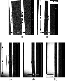
Translaminar fracture analysis invokes Figs 7a&b, which refer to the EPX-CF laminate. Fig.7-a (large square dashed frame) portrays tomographic C-view at the mid-thickness of the damaged specimen; 2D-RARE protocol with 5 repetitions, 50 x 40 mm2 FOV, 312 x 312
S-view, is depicted in Fig.7-b (small square dotted frame). The through-the-width image-slice was at one-quarter (w/4) from the notched-side of the test coupon. At that position, crack opening displacement was still distinctly detectable by MRI, since the damage extended perpendicularly to the specimen length direction.
Delamination fracture analysis requests Figs 7c-e. Fig.7c refers to a tomographic S-view of EPX-CF laminate presenting interply delaminations (rectangular dotted frame) at the mid-length portion of the test coupon. 2D-RARE protocol with 8 repetitions, 160 x 40 mm2 FOV,
312 x 312 pixel matrix size and 11 ms echo-time took 25 minutes for the entire imaging process.
Figure 7-d differs from Fig.7-c in that 2D-FLASH protocol was used towards a shorter exposure time (18 minutes) by applying 10 replications, 160 x 40 mm2 FOV, 192 x 128 pixel
matrix size and 5 ms echo-time. Although higher scan rate implied loss of image quality, it did not prevent one from determining the number of delaminations (which is significantly higher in the EPX-CF laminate, since it contains much more individual plies than PPS-CF, as previously described in Section 2.1) and their length, which are fundamental inputs for practical and theoretical failure analyses of structural composite laminates [66,67]. The extra 7 minutes expended by the former protocol seems to be justifiable when multiple scans are demanded in structural integrity assessments.
Fig.7-e corresponds to a tomographic S-view of thermoplastic PPS-CF laminate via 2D-RARE imaging protocol. The same operational parameters and acquisition time as for the thermosetting EPX-CF laminate in Fig.7-c were utilized. Good image quality was also obtained, indicating that 2D-RARE protocol is suitable for delamination-damage inspection in both classes of polymer matrix composites. Still regarding Figs.7c-e, the number of delaminations present in EPX-CF composite is larger than in PPS-CF laminate.
It is worth mentioning that delaminated FRP coupons would hardly require other than S-view for a full fracture portrayal. This fact constitutes a significant advantage over translaminarly fractured laminates, which invariably demands at least two basic imaging planes to fully delineate this kind of damage.
Unbalanced crack growth
Figures 8a-d present a special situation wherein unbalanced translaminar fracture growth developed in EPX-CF test coupon submitted to 3PB test. Four C-view parallel slices at different through-the-thickness positions of the test specimen reveal dissimilar crack lengths and corresponding crack opening displacements.
shown in Figs8a-d. The largest crack opening displacement (related to the longest crack profile) in one flank of the specimen favored water ingress into the crack (high responsive magnetic resonance region), while in the opposite flank the smallest crack opening displacement (related to the shortest crack profile) prevented water ingress, therefore reducing magnetic resonance signaling in that area.
Figure 8-f depicts similar case related to PPS-CF test coupon, but differently from Fig.8-e no translaminar crack growth developed, but instead a large delamination. Hence, ingress of water allowed MRI depiction of the interply damage (whitish area).
Figures 8g-j show some stages of crack/damage progression in the EPX-CF test coupon, as captured by means of tomographic S-views. For this purpose, parallel slices were imaged, respectively, at four different distances from the notch tip, namely, 1, 3, 4 and 5 mm. The non-symmetrical through-the-thickness crack growth is noticeable, confirming again MRI images in Fig.10. The right-hand side leading edge (indicated by white arrows in Fig.11d-f) is always discernible, whereas the left-hand forefront trends to fade away. Therefore, Fig.8 corroborates previous findings regarding translaminar fracture imaging by MRI (Subsection “Translaminar fracture analysis”), which established that at least two primary view-planes must be used to fully portray that damage type.
It is worth mentioned that research findings here reported can be extended to many engineering applications of composites (other than bioengineering) operating partially or fully immersed in rich-proton media like offshore oil drilling platforms, deep-water structures, bridges, large and / or thick-walled composite marine crafts, and overwrapped pressurized vessels for scramjet engines [68-73].
6. Conclusions
This study evaluated the potential of multislice 3D Computed Tomography Magnetic Resonance Imaging (CT-MRI) for in-vitro nondestructive inspection of glass (G) and carbon (C) fiber-reinforced polymer (FRP) specimens deliberately damaged under well-controlled conditions and subsequently immersed in saline solution simulating biofluids. Main conclusions are as follows:
i. 2D-RARE protocol has proven more adequate than 2D-FLASH for nondestructive MRI examination of translaminar and delamination damages in FRP laminates.
iii. Translaminar and delamination damages can be characterized via MRI in terms of their size, geometry, orientation and positioning in the test pieces.
iv. Surface texture features in CFRP, as well as inner water-rich clusters in GFRP laminate were also well delineated via MRI.
v. Translaminar damage demanded at least two of the three primary MRI tomographic planes (axial, coronal and sagittal) to be fully depicted, whereas delamination damage required just one basic tomographic plane for its entire characterization (sagittal).
vi. Based on the achieved results, MRI is envisioned as valuable nondestructive imaging tool for in-field (in-situ) and laboratorial (ex-situ) inspection and failure analysis of structural FRP laminates operating in hydrogen-rich liquid environments.
Funding Acknowledgements: The authors gratefully acknowledge the scholarships provided by FAPESP (State of São Paulo Research Foundation) to C.L.A. (Processes 2014/00030-7 and 2014/20798-0). The collaboration of M.Sc. Oliveira J.S. and Eng. Vidoto E.L.G. in providing auxiliary MR images and water absorption data is also greatly appreciated.
Author contributions: Tarpani A.C.S.P. performed the analysis and interpretation of data, besides substantial revision of the paper; Alves C.L. was the main responsible for samples preparation, mechanical testing and data acquisition; Tannús A. managed the magnetic resonance imaging laboratory and carried out the experiments; Tarpani J.R. conceived, designed and coordinated the whole project, having drafted the paper.
References
1. Comprehensive composite materials II (2018) PWR Beaumont, CH Zweben Eds., 2nd Ed.,
Elsevier Ltd., 4288p. ISBN 978-0-08-100534-7
2. Petersen R (2016) Carbon fiber biocompatibility for implants. Fibers, Basel. v.4, p.1-13. https://doi.org/10.3390/fib4010001
3. Chung DDL (2003) Composite materials for biomedical applications. In: Composite Materials: Engineering Materials and Processes. 1st Edition, Springer, p.233-243. ISBN
978-1-4471-3734-4
4. Williams DF (2008) On the mechanisms of biocompatibility. Biomaterials, v.29, p.2941-2953. https://doi.org/10.1016/j.biomaterials.2008.04.023
5. Iqbal HMN, Keshavarz T (2017) The challenge of biocompatibility evaluation of biocomposites. Biomedical Composites, 2nd Ed., Woodhead Publishing Series in
Biomaterials, L Ambrosio Ed., p.303-334. ISBN 9780081007525
6. Brockett CL, Carbone S, Fisher J, Jennings LM (2017) PEEK and CFR-PEEK as alternative bearing materials to UHMWPE in a fixed bearing total knee replacement: an
experimental wear study. Wear, v.374-375, p.86-91
https://doi.org/10.1016/j.wear.2016.12.010
7. Ghalme SG, Mankar A, Bhalerao Y (2016) Biomaterials in hip joint replacement. International Journal of Materials Science and Engineering, v.4, p.113-125. https://doi.org/10.17706/ijmse.2016.4.2.113-125
8. Ziran BH, Harris R (2018) Use of carbon fiber-reinforced PEEK for treatment of femur fractures: a small step for implants, a large step in fracture care. Journal of Orthopaedical Trauma, p.e1-e5. https://doi.org/10.1097/BOT.0000000000001285
9. Ong K, Yun M, White K (2015) New biomaterials for orthopedic implants. Orthopedic Research and Reviews, v.7, p.107-130. https://doi.org/10.2147/ORR.S63437
11.Tian L, Tang N, Ngai T, Wu C, Ruan Y, Huang L, Qin L (2019) Hybrid fracture fixation systems developed for orthopaedic applications: a general review. Journal of Orthopaedic Translation, v.16, p.1-13. https://doi.org/10.1016/j.jot.2018.06.006
12.Hillock R, Howard S (2014) Utility of carbon fiber implants in orthopedic surgery: literature review. Reconstructive Review, v.4, p.23-32. https://doi.org/10.15438/rr.v4i1.55
13.Hak DJ, Mauffrey C, Seligson D, Lindeque B (2014) Use of carbon-fiber-reinforced composite implants in orthopedic surgery. Orthopedics, v.37, p.825-830. https://doi.org/10.3928/01477447-20141124-05.
14.Scholz MS, Blanchfield JP, Bloom LD, Coburn BH, Elkington M, Fuller JD, Gilbert ME, Muflahi SA, Pernice MF, Rae SI, Trevarthen JA, White SC, Weaver PM, Bond IP (2011) The use of composite materials in modern orthopaedic medicine and prosthetic devices: a review. Composites Science and Technology, v.71, p.1791-1803. https://doi.org/10.1016/j.compscitech.2011.08.017
15.Longo JA, Koeneman JB (2000) Orthopedic applications of carbon fiber composites. In: Biomaterials Engineering and Devices: Human Applications, 1st Ed., DL Wise, DJ
Trantolo, KU Lewandrowski, JD Gresser., MV Cattaneo, MJ Yaszemski Eds., Humana Press, Totowa-NJ, p.203-214. ISBN 978-1-59259-197-8
16.Salernitano E, Migliaresi C (2003) Composite materials for biomedical applications: a review. Journal of Applied Biomaterials and Biomechanics, v.1, p.3-18. https://doi.org/10.1177/228080000300100102
17. Ramakrishna S, Mayer J, Wintermantel E, Leong KW Biomedical applications of polymer-composite materials: a review Composites Science and Technology (2001), v.61, p.1189-1224. https://doi.org/10.1016/S0266-3538(00)00241-4
18.Evans SL, Gregson PJ (1998) Composite technology in load-bearing orthopaedic implants. Biomaterials, v.19, p.1329-1342. https://doi.org/10.1016/s0142-9612(97)00217-2
Damage Detection in Composite Materials, JE Masters Ed., p.256-271. https://doi.org/10.1520/STP14578S
20.Vercio RC, Basmajian HG (2019) Fracture of a carbon fiber reinforced intramedullary femoral nail. Journal of the American Academy of Orthopaedic Surgeons, v.27, p.e585-e588. https://doi.org/10.5435/JAAOS-D-17-00483
21.Baker D, Kadambande SS, Alderman PM (2004) Carbon fibre plates in the treatment of femoral periprosthetic fractures. Injury, v.35, p.596-598, https://doi.org/10.1016/j.injury.2003.10.014
22.Li C, Granger C, Del Schutte Jr MSH, Biggers Jr SB, Kennedy JM., Latour Jr RA, (2003) Failure analysis of composite femoral components for hip arthroplasty. Journal of Rehabilitation Research and Development, v.40, p.131-145. https://doi.org/10.1682/JRRD.2003.03.0133
23.Li C, Granger C, Del Schutte Jr MSH, Biggers Jr SB, Kennedy JM., Latour Jr RA, (2002) Progressive failure analysis of laminated composite femoral prostheses for total hip arthroplasty. Biomaterials, v.23, p.4249-4262. https://doi.org/10.1016/S0142-9612(02)00188-6
24.Allcock S, Ali MA (1997) Early failure of a carbon-fiber composite femoral component. Journal of Arthroplasty, v.12, p.356-358. https://doi.org/10.1016/S0883-5403(97)90038-3
25.Basso T, Klaksvik J, Syversen U, Foss OA (2014) A biomechanical comparison of composite femurs and cadaver femurs used in experiments on operated hip fractures. Journal of Biomechanics, v.47, p.3898-3902. https://doi.org/10.1016/j.jbiomech.2014.10.025
26.Elfar J, Stanbury S (2014) Composite bone models in orthopaedic surgery research and education. Journal of American Academy of Orthopaedic Surgery, v.22, p.111-120. https://doi.org/10.5435/JAAOS-22-02-111
28.Heiner AD (2008) Structural properties of fourth-generation composite femurs and tibias. Journal of Biomechanics, v.4, p.3282-3284. https://doi.org/10.1016/j.jbiomech.2008.08.013
29.Cristofolini L, Viceconti M (2000) Mechanical validation of whole bone composite tibia models. Journal of Biomechanics, v.33, p.279-288. https://doi.org/10.1016/s0021-9290(99)00186-4
30.Cristofolini L, Viceconti M, Cappello A, Toni A (1996) Mechanical validation of whole bone composite femur models. Journal of Biomechanics, v.2, p.525-535. https://doi.org/10.1016/0021-9290(95)00084-4
31.Kashi A, Saha S (2010) Mechanisms of failure of medical implants during long-term use. In: Biointegration of Medical Implant Materials, Science and Design, 1st Edition, C
Sharma Ed., Woodhead Publishing Series in Biomaterials, p.326-348. ISBN 9781845695095
32.Duchene P, Chaki S, Ayadi A, Krawczak P (2018) A review of non-destructive techniques used for mechanical damage assessment in polymer composites. Journal of Materials Science, v.53, p.7915-7938. https://doi.org/10.1007/s10853-018-2045-6 33.Clayden NJ, Jackson P (1994) Nondestructive testing of thermoplastic composites by
NMR imaging and localised spectroscopy. Journal of Nondestructive Testing and Evaluation, v.11, p.293-304. https://doi.org/10.1080/10589759408956410
34.Nuclear Magnetic Resonance Imaging in Medicine and Biology (1986), 1st Ed., PG
Morris, SC Morris Eds. Clarendon Press, 388p. ISBN 0 19 855155 X
35.Craciun H, Mankad K, Lynch J (2015) Risk management in radiology departments. World Journal of Radiology, v.7, p.134-138. https://doi.org/10.4329/wjr.v7.i6.134 36.Grosso M, Pacheco CJ., Arenas MP, Lima AHM, Margarit-Mattos ICP, Soares SD,
Pereira GR (2018) Eddy current and inspection of coatings for storage tanks. Journal of Materials Research and Technology, v.7, p.356-360. https://doi.org/10.1016/j.jmrt.2018.05.006
38.Bougherara H, Rabim E (2011) A preliminary biomechanical assessment of a polymer composite hip implant using an infrared thermography technique validated by strain gage measurements. Journal of Biomechanical Engineering, v.133, p.074503-1/074503-6. https://doi.org/10.1115/1.4004414
39.Magnetic resonance imaging: physical principles and sequence design (2014), 1st Ed.,
RW Brown, YCN Cheng, EM Haacke, MR Thompson, R Venkatesan Eds., Wiley, 914p. ISBN: 9780471720850
40.Characterization of composite materials (2009), 1st Ed, H Ishida, CR Brundle, CA Evans
Jr. Eds., Momentum Press, 277p. ISBN 978-1-60650-191-7
41.Rothwell WP (1985) Nuclear magnetic resonance imaging. Applied Optics, v.24, p.3958-3968. https://doi.org/10.1364/AO.24.003958
42.Rothwell WP, Holecek DR, Kershaw JA (1984) NMR imaging: study of fluid absorption by polymer composites. Journal of Polymer Science, v.22, p.241-247. https://doi.org/10.1002/pol.1984.130220501
43.Jafar MM, Reeves J, Ruthven MA, Dean CJ, MacDougall ND, Tucker AT Miquel ME (2016) Assessment of a carbon fibre MRI flatbed insert for radiotherapy treatment planning. The British Journal of Radiology, v.89: paper 20160108. https://doi.org/10.1259/bjr.20160108
44.Morris RH, Trabi CL, Spicer A, Langmack K, Boersma W, Weightman JS, Newton MI (2019) A natural fibre FRP composite material for multi-modal medical imaging and radiotherapy treatment. Materials Letters, v.252, p.S289-292 https://dx.doi.org/10.1016/j.matlet.2019.05.119
45.Meng X, Du Z, Wang Y (2018) Feasibility of magnetic resonance imaging monitoring of postoperative total knee arthroplasty without metal artifacts: a preliminary study of a novel implant model. BioMed Research International, article ID 8194670, 5 p. https://doi.org/10.1155/2018/8194670
47.Tarpani JR, Portela AMA (2017) Magnetic resonance imaging of mechanically damaged and liquid-contaminated core cells in polymer composite sandwich panels. Journal of Sandwich Structures and Materials, 30p. https://doi.org/10.1177/1099636216681698 48.Marble AE, Laplante G, Mastikhin IV, Balcom BJ (2009) Magnetic resonance detection
of water in composite sandwich structures. NDT & E International, v.42, p.404-409. https://doi.org/10.1016/j.ndteint.2009.01.010
49.Laplante G, Marble AE, Macmillan B, Sullivan PL, Colpitts BG, Balcom BJ (2005) Detection of water ingress in sandwich structures: a magnetic resonance approach. NDT & E International, v.38, p.501-507. https://doi.org/10.1016/j.ndteint.2005.01.006
50.Principles of nuclear magnetic resonance microscopy (1991), 1st Ed., PT Callaghan Ed.,
Clarendon Press, 516p. ISBN 0198539975
51.Surgical treatment of hip arthritis reconstruction, replacement, and revision (2009), 1st
Ed., H William, P Javad, BB Parvizi Eds., 544p. ISBN: 9781416058984
52.Macdonald W, Carlsson LV, Charnley GJ, Jacobsson CM (1999) Press-fit acetabular cup fixation: principles and testing. In: Proceedings of the Institution of Mechanical Engineers: Part H - Journal of Engineering in Medicine, v.213, p.33-39 https://doi.org/10.1243/0954411991534780
53.Mehboo LLH, Chang SH (2014) Application of composites to orthopedic prostheses for effective bone healing: a review. Composite Structures, v.118, p. 328-341. https://doi.org/10.1016/j.compstruct.2014.07.052
54.Garcia FG, Leyva ME, Queiroz AAA, Higa OZ (2009) Epoxy networks for medicine applications: mechanical properties and in-vitro biological properties. Journal of Applied Polymer Science, v.112, p.1215-1225. https://doi.org/10.1002/app.29528
55.Hastings GW (1978) Carbon fibre composites for orthopaedic implants composites. Composites, v.9, p.193-7. https://doi.org/10.1016/0010-4361(78)90345-2
56.Hastings GW (1986) Carbon and plastic materials for orthopaedic implants. In: Materials Sciences and Implant Orthopedic Surgery. NATO ASI Series (Series E: Applied Sciences), R Kossowsky, N Kossovsky Eds., Springer, vol 116, p.263-284. ISBN 978-94-010-8492-5
osteogenesis as a novel orthopedic implant. Royal Society of Chemistry Advances, v.7, p.559-573. https://doi.org/10.1039/C6RA25526D
58.Han X, Yang D, Yang C, Spintzyk S, Scheideler L, Li P, Li D, Geis-Gerstorfer J, Rupp F (2019) Carbon fiber reinforced PEEK composites based on 3D-printing technology for orthopedic and dental applications. Journal of Clinical Medicine v.8, 17p. https://doi.org/10.3390/jcm8020240
59.Ali MS, French TA, Hastings GW, Rae T, Rushton N, Ross ER, Wynn-Jones CH (1990) Carbon fibre composite bone plates development, evaluation and early clinical experience. Journal of Bone Joint Surgery Br., v.72B, p.586-91. https://doi.org/10.1302/0301-620X.72B4.2380209
60.Dragomir-Daescu D, Rezaei A, Rossman T, Uthamaraj S, Entwistle R, McEligot S, Lambert V, Giambini H, Jasiuk I, Yaszemski MJ, Lu L (2017) Method and instrumented fixture for femoral fracture testing in a sideways fall-on-the-hip position. Journal of Visualized Experiments, v.126, e54928, 9p. https://doi.org/10.3791/54928
61.Graf H, Steidle G, Lauer UA, Schick F (2005) RF enhancement and shielding in MRI caused by conductive implants: dependence on electrical parameters for a tube model. Medical Physics, v.32, p.337-342. https://doi.org/10.1118/1.1843351
62.Valdes LB (1954) Resistivity measurements on germanium for transistors. Proceedings of the Institute of Radio Engineers, v.42, p.420-427. https://doi.org/10.1109/JRPROC.1954.274680
63.Kokubo T, Kushitani H, Sakka S, Kitsugi T, Yamamuro T (1990) Solutions able to reproduce in-vivo surface structure changes in bioactive glass ceramic A-W. Journal of Biomedical Materials Research, v.24, p.721-734. https://doi.org/10.1002/jbm.820240607 64.Sood B, Pecht M (2018) The effect of epoxy/glass interfaces on CAF failures in printed circuit boards. Microelectronics Reliability, v.82, p.235-243. https://doi.org/10.1016/j.microrel.2017.10.027
65.Powers DA (2009) Interaction of water with epoxy. Sandia National Laboratories Report - SAND2009-4405, 57p. https://prod-ng.sandia.gov/techlib-noauth/access-control.cgi/2009/094405.pdf
67.Application of fracture mechanics to composite materials (1989), v.6, K Friedrich Ed., Elsevier Science Publishing, 686p. ISBN 9780444597212
68.Silva LV, Silva FW, Tarpani JR, Forte MMC, Amico SC (2016) Ageing effect on the tensile behavior of pultruded CFRP rods. Materials and Design, v.110, p.245-254. https://doi.org/10.1016/j.matdes.2016.07.139
69.Wang X, Wu G, Wu Z, Dong Z, Xie Q (2014) Evaluation of prestressed basalt fiber and hybrid fiber reinforced polymer tendons under marine environment. Materials and Design, v.64, p.721-728. https://doi.org/10.1016/j.matdes.2014.07.064
70.Yu Y, Yang X, Wang L, Liu H (2006). Hygrothermal aging on pultruded carbon fiber/vinyl-ester resin composite for sucker rod application. Journal of Reinforced Plastics and Composites, v.25, p.149-160. https://doi.org/10.1177/0731684405055462 71.Keller T, Theodorou N, Vassilopoulos A, Castro J (2016) Effect of natural weathering
on durability of pultruded glass fiber-reinforced bridge and building structures. Journal of Composites for Construction, v.20, p.1-9. https://doi.org/10.1061/(ASCE)CC.1943-5614.0000589
72.Hossain E (2011) The current and future trends of composite materials: an experimental study. Journal of Composite Materials, v.45, p.2133-2144. https://doi.org/10.1177/0021998311401066