c
Owned by the authors, published by EDP Sciences, 2012
Computational evaluation of some lower limbs protective systems
under explosive loading
J.C. Calle, R. Coronado, J. Rodriguez, and J.P. Casas
Universidad de los Andes, Mechanical Engineering Department, Bogot ´a, Colombia
Abstract. Different types of protective equipment for human lower limb, such as boots and gaiters, have been developed in order to reduce the injury caused by blast antipersonnel-mines. Damage is mainly studied by the energy transmitted to the extremity that has stepped on the mine; nonetheless, side effects that may affect adjacent limbs cannot be left aside. This study is divided into three stages due to the complexity in modeling the different phenomena related to the problem. The first stage is the study of the energy transmitted when a mine is activated. Different results are gathered according to the variation of parameters such as: deep of burial, standoffbetween ground and protective equipment, explosive mass, energy absorbing material placed between the ground and the protected limb, and computational issues like the distance of the boundary conditions and the discretization level. The second stage is the base and first approximation to the modeling and evaluation of lower limb behavior. It includes the interaction of the detonation products and a lower limb that is placed in a mechanical measuring device. The energy transferred to the mechanical device is correlated to the damage caused by the explosion products in an attempt to validate previously experimental data. Finally, in the third stage, the side effect on the lower contiguous leg is assessed: pressure and temperature measures are taken at different distances according to the human pace in order to evaluate the worst-case scenario. The first and third stages propose different material arrangements or configurations to reduce the energy transmitted to the mechanical device and to mitigate damage caused to the contiguous limb respectively. All the three stages are simulated using two-dimensional (2D) hydrocode Ansys AUTODYNR and material previously reported in literature.
1 Introduction
The response of materials and structures to impact and shock-waves is an area of intense current research [1]. One of the reasons of this interest is to protect human lives from explosive weapons and fragmentation devices. Since World War II, the survivability from battlefield has increased from 69.7% to 88.6% most recently in Iraq [2]. In Colombia, the number of casualties caused by im-provised explosive devices i.e. ant-personnel blast mines (APBM), is approximate to ten thousand since 1990. [3]. For this reason, the correct design of blast and fragment protective structures with an accurate selection of materials is necessary.
APBM are basically an explosive, like C-4 or pentolite, with a charge size between 50 to 100 gr, contained in a plastic case with some activation device. It is intended to damage the area close to it and not to cause fatality [4]. When dealing with explosive devices it is neces-sary to understand first how the shock wave and deto-nation products interact with the surrounding structures, behavior of material that conforms them, and how shock waves propagate in material interface i.e. sandwich-like structures and boundary layers.
Commercially there is a wide range of anti-mine boots which show some similar configurations in its protective structure: an outside V-shape profile in a rigid material, composite materials or periodical lattice structure.
The outside part of the protective structure is mainly an oblique blast deflector of high impedance material. This deflector is used as a counter-measure to redirect the explosion products away from the protected vehi-cle/person/building. Actually, there are algebraic equations [5], experimental data [6] and numerical shape
optimization simulations [7] that relate the effect of vari-ous changes in the mine/target geometry on the resulting impulse/momentum transferred. All of the results showed that the V-shape profile offers the minimum impulse value compared with convex, concave, and combinations of this shapes in structures.
There are some well know materials to protect against blast products and fragments. The principal characteristic of these materials is the ability to attenuate high pressure waves by means of large deformation and/or anisotropic behavior that promote the shock wave to travel in some specific direction. Cellular materials are one of these kind, depending of the type of blast wave and its amplitude, the pressure pulse can be either amplified or attenuated de-pending on the material stiffness and thickness [8] . How-ever, it has demonstrated that placing of a high impedance material in front of cellular one or even, the combination of materials with different properties, specially in their impedance difference, will lead to a wave decoupling effect [9] and reduce the transmitted pressure.
The evaluation of the APBM output in commercially available demining footwear has been centered in the energy and load transmitted to mechanical devices and surrogate legs. The main focus of these researches is to establish a relation between quantitative data and injury caused by an explosive device. They found some important values in terms of transmitted energy to a piston-like measuring device [10] and record the strain in a surrogate leg tibia [11] that will help in the establishment of a limit value for design of leg protection systems. Parallel to the experimental investigations, surrogate simplified lower legs are under development with the help of numerical modeling techniques to mimic the response of real legs to blast loading [12] and different explosives [13]. Their
results show good agreement with experimental data in the first microseconds of the event and establish some basis for the use of some numerical solvers i.e.LagrangeandALE. The present study is divided into three stages due to the complexity of the phenomena that is analyzed and is based in the implementation in non-lineal explicit software AUTODYNR 2D. The first part deals with computational discretization of the domain, convergence of the solution and boundary conditions when measuring the energy trans-mitted to a rigid mass. It also includes the implementation of some protective materials and a multilayer configuration to reduce the energy transmitted. The second part is a first computational approximation to validate experimental data found in literature [10]. The implementation of bio-logical materials models are treated as well as numerical solvers issues. Finally, the third part is the modeling of the side effects caused by the explosive products when they reach a V-shape profile. Pressure and temperature data are gathered in regions of interest when a V-shape profile deflector is used. Furthermore, taking in consideration human anthropometry a protective device is implemented to protect the contiguous leg.
The computational evaluation is performed in non-lineal explicit software AUTODYNR using 2D axil-symmetry. The equation of state, strength and failure mod-els of the different materials used in this study are based on previously published information. The development of the materials models is out of the scope of this study.
2 Numerical modeling
In this section, a computational methodology is used to evaluate the behavior of a) different protective material configurations and b) a surrogate lower limb when an APBM is activated. It presents the discretization of the domain, boundary conditions and materials implemented in the software AUTODYNR.
2.1 Determination of simulation parameters
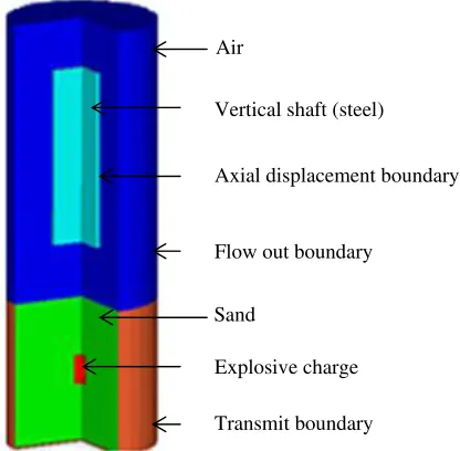
The experimental device used in some test for quantified transmitted energy to a surrogate leg [10] and to compare experimental data with simulations [14] is simplified in the computational model. It consists of a vertical displacement shaft placed above a sand container were the explosive charge is placed. In the end of the shaft that faces the sand, the test samples are placed. The measure is taken by the displacement of the shaft and therefore the potential energy is calculated, see figure 1. The considerations taken involve: the structure, shaft, must not absorb energy so the material must support the explosive load, since the explosive event is at a scale of milliseconds the protective equipment absorbs all the energy it can before the shaft began its motion. For these reasons, it can be assumed that the transmitted energy is the difference between the energy of the explosion that reach the sample and the absorbed energy of the protective structure.
When dealing with this type of phenomena it is impor-tant to take care of the variables involve. Among consid-erations presented in literature [14] are: mass of explosive,
Vertical shaft (steel)
Transmit boundary Flow out boundary
Axial displacement boundary
Explosive charge Air
Sand
Fig. 1.Simplified computational setup and boundary conditions.
reaction mass, deep of burial and standoffdistance. These variables will not be treated here but a detailed explication can be found in previous works [14].
The environment, composed by air (at one atmosphere of pressure), sand and explosive charge, is modeled in an Euler multi-material formulation, the steel shaft is modeled by a Lagrange solver; their interaction is set to polygon free couple type. Boundary conditions of transmit and flow out [15] are putted in sand and air respectively, a boundary of zero displacement is placed in the side of the shaft to avoid transversal movements. All the materials used in this part of the numerical simulation are in the AUTODYN default material library.
To determine the simulation parameters like distance from the charge to the boundaries conditions and mesh size, radial distance is augmented and the size of the cells is reduced. A convergence study is carried out for the velocity of the shaft in terms of radial distance of the boundaries conditions from the explosive charge and mesh size. This is due mainly to avoid numerical problems in the boundaries, like wave reflection, that introduce a misleading lecture in the shaft’s velocity and to have an appropriate balance between computational cost and accuracy of the solution.
Once the above cited numerical parameters are known, additional simulations are carried out to evaluate some setup parameter in the computational simplification that is made. Deep of burial, explosive mass and distance between the top surface of the sand and bottom end of the shaft (standoff) are varied in order to evaluate its maximum velocity. Both, numerical and setup parameters are the basis of further simulations: a) implementation of protective equipment to reduce energy transferred and b) behavior of a surrogate lower leg.
2.2 Protective equipment for reducing energy transfer
also treat each characteristic of it in separate stages. For this reason, the selection of material is according to the properties available in literature for high strain rates and their impedance. The materials selected for this stage are: a PVC foam [16], UHMWPE [17], aluminum honeycomb. [18], and a rigid polyurethane foam [19]. All of them are modeled with a Lagrange solver.
Each one of the above materials is placed in the space between the top surface of the sand and the bottom end of the shaft. The evaluation is carried out by augmenting the thickness of the layer between 12 and 50 mm of each material. When the protective system is a sandwich-like multilayer structure, the thickness is the same for the layers and the modification is carried by augmenting the thickness of the whole structure.
2.3 Surrogate lower leg
When dealing with impact in the human torso, the be-havior is rate-dependent or viscoelastic and [20] and it can cause intern injury without penetration mainly by the shock waves traveling in the thoracic cavity. This particular behavior is also seen in in lower limb when an explosive device is activated below it [2].
In this stage the leg is modeled as concentric tubes, an inner one representing the bone and the outer one is soft tissue with de approximate dimension of a lower limb, as done previously by [12, 13]; taking care of the considerations reported about the input stress [21]. The surrogate lower leg is modeled as a simplified model of an experimental one found in literature [10], see figure 2. In the study two solvers were evaluated due to the large de-formation the materials can withstand: arbitrary Lagrange-Euler (ALE) and Lagrange. With the same materials model reported [22] the solvers are assessed in terms of the transmitted energy to the shaft.
2.4 Side effects on lower limb
Most of the commercially demining boots consist of a V-shape profile, as was stated earlier, that deflect the blast wave coming from the explosion. The deflection of the detonation products may cause serious injury to the con-tiguous leg because it receives the bound shock and the one coming directly from the explosive device. The proposed model consists of a shaft, the same as the other stages, with a V-shape in the bottom end. Gauges are placed at distance according to stand-up and pace position of the legs [23] for determine the place of maximum pressure and temperature.
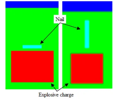
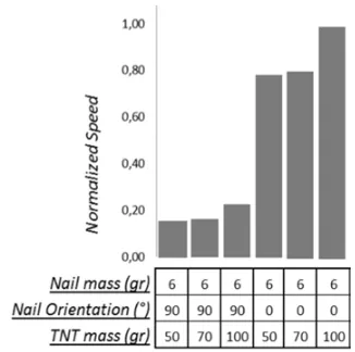
Some of the APBM contain ferrous materials like shrapnel that are ejected at great velocity or fragments of the mine container. To evaluate this effect, the shrapnel is modeled as a nail of mass varied between 6 and 10 gr, a range of commercially available nails. Other consideration is how the position of the fragment affect the velocity it acquires, for this the fragment is placed at 0◦and 90◦from a horizontal reference, figure 3. Furthermore, the mass of the explosive is varied from 50 gr to 100 gr of TNT to evaluate the speed of the fragment.
Air
Shaft
Bone
Soft tissue
Rubber sole Explosive Charge Sand
Fig. 2.Proposed computational model for a surrogate lower leg.
Fig. 3.Computational model for simulation of fragment.
Based on the result obtained from the above simu-lations, the surrogate contiguous leg is modeled in two parts: an outer cylinder of ballistic gel with an interior of wood. The replacement of the bone is based on a literature review that showed a good correlation when compared with cedar wood [24]. The protection of this leg must not have influence in the pace of the person that wears it, for this reason it have a limit value for the thickness
Fig. 4.Computational model for blast and fragment protection.
Fig. 5.Boundary conditions (x) and mesh size analysis (+).
3 Results and discussion
3.1 Simulation parameters
The results of simulations varying the radial distance be-tween the charge and the boundary condition are showed in figure 5. The normalized shaft velocity, based on the max-imum value obtained in these series of simulations, tends to have a constant maximum velocity above certain value. In terms of mesh size, the appropriate element density for having a tendency in the shaft velocity is shown in figure 5. These trends are appropriate in both directions: radial and longitudinal of the 2D axial-symmetry simulation. It is worth to note that the shaft must be in the Euler domain, environment, to have a correct interaction between both solvers.
Previously presented study [14], show that transferred energy to a piston apparatus is dependent of some pa-rameters. The variables analyzed in that study include: mass of explosive, mass of the piston or reaction mass, deep of burial and standoffdistance. They present exper-imental results and computational validation with good agreement between both. Some results show that when the mass of explosive in duplicated the average energy transmitted to the piston is three times more. Also, the mass of the piston must be taken into account because the shock wave tries to find the path of lower resistance. In terms of deep of burial, the show that there is a range in this variable where the transmitted energy is nearly constant.
Fig. 6.Transferred energy to different protective structures: air
(♦), UHMWPE (∗), PVC foam (), PU foam (x), Honeycomb () and multilayer (◦) for a charge of 100 gr of TNT vs. deep of burial.
Fig. 7.Material status for a computational lower leg at 0,25 ms.
3.2 Protective equipment
The normalized results, in terms of the maximum value in the series of simulation for the different protective systems, see figure 6, show that the behavior of UHMWPE and PVC foam are similar for all explosive charges (50 gr to 190 gr of TNT) and thicknesses evaluated (12 mm to 50 mm). The rigid PU foam has similar values when compared to air and honeycomb for charges above 100 gr of TNT, making rigid foams and honeycomb structures attractive when designing for blast events and not taking into consideration side effect. It also shows that a proper material selection must be done because not all the foams protect from blast events. The energy transferred by the multilayer structure is always between the values of air and UHMWPE, the lowest and higher one respectively.
3.3 Surrogate lower leg
Fig. 8.Simulation results for normalized nail speed.
literature [12], the leg is modeled using viscoelastic and elastic strength models for tissue and bone respectively according to reported data [22]. Two types of simulation are made and in both, the model for the environment is the same as the one exposed above. In one of the simulations leg is modeled using a Lagrange solver and in the other one an ALE one. Same as for the protec-tive equipment, the leg is attached to the shaft and the transmitted energy is measured in term of the maximum velocity.
Using the same material models for both types of solvers, the results show a great difference in comparison with the expected one, above 80%. The transmitted energy from the Lagrange leg is inferior to the ALE one. These show that the correct selection of the numerical solver is important.
3.4 Side effects on lower limb
The figure 8 presents the results of different simulations, in which, three different variables were evaluated. The results show that the fragment orientation is determinant on its final speed, leaving the most critical situation when the fragment orientation is 0◦. Another aspect that is important to highlight is that the fragment final speed is determined by its mass, the lighter the fastest. Finally, the mass of the explosive is proportional to the fragment speed.
One of the most critical parameter of an APBM is the mass of the explosive [14]. The simulations show that the worst case distance is when the person is in stand-up position; at this distance is where the peak values of pressure are presented.
As it is notice, the protection system should be able to protect the lower limb from two events, blat wave and the impact of the fragments/shrapnel. For these reason, a combination of different thicknesses of aramids fabric and PVC foam were simulated. The proposed protective system can stop the fragment, but further investigation is needed to evaluate the penetration of different fragment orientations and multi-impact. Also it serves as a wave attenuator, reducing the incident pressure wave to magni-tudes the body can withstand.
4 Conclusion
When using computational simulation to validate exper-imental data, it is important to know the influence of boundary conditions, mesh size and the correct use of the solvers (Euler, Lagrange, ALE, etc.) to have good agreement when using non-lineal explicit software.
Some of the materials implemented in the protection system show a comparable behavior to the air, but anyone show a less energy transmitted. The thickness of the material layer, deep of burial and standoff have import relation in the transferred energy in a shaft-like measuring device.
Independently of the orientation of the projectile (0◦ and 90◦), the protection system prevents the penetration stopping it before it reaches the foam into the protection system. Knowing the results of the simulation mention on the explosive wave analysis and the nail speed analysis (Peak of pressure, peak of temperature and nail maxi-mum speed) the disposition of the two materials were arranged to diminish the explosive pressure and stops the shrapnel.
Acknowledgements
The material presented in this article is supported by the Struc-tural Integrity Group (GIE) of the Department of Mechanical Engineer and the Military Industry (INDUMIL) of Colombia.
References
1. M. A. Meyers,Dynamic behavior of materials. (Wiley, New York, 1994).
2. A. Ramasamy, A. M. Hil, S. Masouros, I. Gibb, A. M. J. Bull, and J. C. Clasper, J. R. Soc. Interface (8), 689 (2011).
3. 2011.
4. D. Cronin, K. Williams, C. R. Bass, P. Magnum, F. Dosquet, D. Bergeron, and J. van Bree, 2004.
5. J. E. Tremblay, 1998.
6. C. Anderson, T. Behner, and C. Weiss, International Journal of Impact Engineering (2011).
7. G. Gurumurthy, Massachusetts Institute of Technol-ogy, 2008.
8. A. Makris, D. L. Frost, J. Nerenberg, and J. H. S. Lee, Proceedings of the 20th International Symposium on shock Waves, Pasadena, CA 2, 1387 (1996); J. Nerenberg, J. A. Nemes, D. L. Frost, and A. Makris, Proceedings of the 21th International Symposium on shock Waves, Australia1, 91 (1997).
9. O. E. Petel, F. X. Jett´e, S. Goroshin, D. L. Frost, and S. Ouellet, Shock Waves (21), 215 (2011).
10. J. M. L. Mah, M. P. Braid, R. W. Fall, and I. Anderson, 2007.
11. D. Bergeron, G. Coley, R. Fall, and I. Anderson, 2006.
13. D. Cronin, (2004).
14. J. A. H. Uribe, V. H. B. Poveda, and J. P. C. Ro-druiguez, 26th International symposium on ballistics, Miami, FL1, 187 (2011).
15. Century dynamics, ANSYS AUTODYN User’s Manual. Release 13.0. (Canonsburg, PA, USA, 2010).
16. I. M. Daniel and J. M. Cho, Experimental Mechanics 51(8), 1395 (2011); I. M. Daniel and J. M. Cho, Con-ference Proceedings of the Society for Experimental Mechanics Series1, 121 (2010).
17. P. W. A. Stijnman, Composites26(8), 597 (1995). 18. V. Bastidas, Universidad de los Andes, 2010. 19. B. C. Wai, Naval postgraduate School, 2009.
20. G. J. Cooper and D. E. M. Taylor, J R Army Med Corp (135), 58 (1989).
21. S. A. Oerder and G. N. Nurick, IUTAM Precceding on Impact biomechanics: from funtamental insights to applications, 51 (2005).
22. J. Roberts, J. O’Connor, and E. Ward, J. Trauma (2005).
23. J. Panero and M. Zelnik,Las dimensiones humanas en los espacios interiores, 11 ed. (Gustavo Gili, 2006); J. Perry and J. Burnfield,Gait analysis: Normal and pathological function, 2 ed. (SLACK Incorporates, 2010).