* Corresponding author: [email protected]
Development and Application of 3.7GHz LHCD system on HL-2A
and Development of RF Heating system on HL-2M
XingYu Bai1,*, Bo Lu1, Hao Zeng1 , Jun Liang1, Chao Wang1, GuoLiang Xiao1,3, He Wang1, YaLi Chen1, JieQiong Wang1, Kun Feng1, ShaoDong Song1, Mei Huang1, Jun Rao1, XianMing Song1, Rui Mao1, Jun Cheng1, YiPo Zhang1, DeLiang Yu1, Yan Zhou1, ZhongBing Shi1, Annika Ekedahl2, Julien Hillairet2, Emmanuel Bertrand2, Lena Delpech2, Gerardo Giruzzi2, Tuong Hoang2, Roland Magne2, Didier Mazon2, Yves Peysson2, XiaoLan Zou2 and the HL-2A Team1
1Southwestern Institute of Physics (SWIP), P.O. Box 432, Chengdu, China.
2CEA, IRFM, F-13108 Saint-Paul-lez-Durance, France
3Department of Engineering Physics, Tsinghua University, Beijing, China.
Abstract. The first Lower Hybrid (LH) experiments were carried out with a Passive-Active Multijunction (PAM) launcher in H-mode plasmas. The experiments were performed on the HL-2A tokamak with the new 3.7 GHz LHCD system, installed and tested by SWIP in collaboration with CEA/IRFM. The ELMs and local gas impact on LH power coupling was studied in the experiments. The coupled LH power in HL-2A was 200-500kW at large gap at the first experiments and reaches 900 kW now in H-mode, while it reaches 1MW in L-mode. The LH experiments on HL-2A show that the PAM launcher is a viable concept for high performance scenarios. The LH power can be coupled at large plasma-launcher gap, and assist in triggering and sustaining H-modes. Finally, an overview of the RF heating systems for the tokamak HL-2M is given. HL-2M will dispose of a 4 MW LH system and a 8 MW ECRH system, both of which are currently under installation at SWIP.
1 Introduction
Lower hybrid current drive (LHCD) is a well known method of non-inductive current drive in tokamaks, which has been used successfully in tokamaks around the world since the early 1980s. A fraction of the plasma current is replaced by the non-inductively LH driven current in the tokamak by injecting LHW into one toroidal direction, which can increase the duration of the plasma discharge[1].
In view of foreseeing a LH system for the second phase of ITER [2], a relevant LH launcher design, the passive-active multijunction (PAM), has been developed [3]. The first experimental test of a PAM module was carried out in the FTU tokamak [4, 5]. Following this, a PAM launcher was designed and constructed for Tore Supra [6], demonstrating long pulse operation at high coupled power (2.7 MW, 80 s) and ITER-relevant power density [7]. So far, the PAM experiments in FTU and Tore Supra have shown excellent results of power handling and coupling at large plasma-launcher distances, making it an attractive launcher design for
operation in high performance scenarios and in long pulses.
However, this has so far only been demonstrated in L-mode plasmas. Now, as a part of the 3.7 GHz LHCD system constructed on HL-2A tokamak, the third PAM launcher is developed and applied, making it possible to carry out LH experiments in H-mode plasmas by PAM antenna.
2 LHCD system description
Fig. 1. Schematic layout of the 3.7 GHz LHCD system.
2.1. PAM launcher
The PAM launcher consists of 16 modules, with four active and four passive grills each, mounted in four rows and four columns. One passive grill is added at the end of each toroidal row, resulting in four rows with 16 active and 17 passive grills (see photo in Fig. 2). The size parameters of the PAM mouth are width = 365 mm; height = 325 mm.
Fig. 2. Photo of the PAM launcher in HL-2A
A dedicated gas puffing system with three poloidal injection points is installed next to the launcher mouth, on the left of the launcher, signed by the arrows in Fig 2. Local gas puffing near LH launchers has been used routinely, for example in JET [9] and EAST [10], as a method to increase the local density and improve the LH coupling, in particular during H-mode operation. A set of Langmuir probes, consisting of a total of eight probes mounted at two radial locations, is installed on the right hand side of the launcher mouth. The probes allow measuring the electron density at two radial locations and will thus also allow deducing the density and temperature decay lengths at the launcher location.
The ALOHA coupling code [11] was used for defining the design parameters for the PAM launcher. The peak parallel refractive index was chosen to n//0 =
2.75, in order to allow accessibility of the LH wave in
HL-2A plasmas. The width and height of each grill are 8.8 mm and 72.14 mm, respectively, with a wall thickness of 2.2 mm. The depth of the passive grill is 24.5 mm, i.e. a quarter of a wavelength. According to the thermal and electromagnetic force analysis, the launcher is made of copper to avoid local overheating in arcing and covered by stainless steel in order to protect the antenna from the twisting in plasma disruption. As the pulse duration is less than 2.0 s, no active cooling is installed on the launcher. The launcher can be moved in the radial direction as much as 100 mm in order to have a good coupling in different discharge conditions. Graphite protection tiles are installed around the front of the launcher, protruding by 2 mm in front of the launcher mouth. ALOHA-code analysis shows that the power reflection coefficient, averaged over the 16 modules, is less than 3% when the electron density at the launcher mouth is larger than 2×10¹⁷ m-3, the cut-off density for
the LH wave being nco = 1.7×10¹⁷ m-3 at f = 3.7 GHz.
2.2. Wave source
The PAM launcher is fed by four klystrons, giving out 500 kW RF power maximum via two ports each. The klystrons are powered by a high-voltage power supply (HVPS) and several auxiliary power supplies including a filament heater power supply, three electromagnet power supplies, two ion pump power supplies and an anode power supply modulator for each klystron, as suggested. But the klystrons are operated in totally a new way for the TH2013A type. A set of divider resistance is chosen to obtain the anode voltage from the cathode HVPS, replacing the anode high voltage modulator, making the HVPS system much simpler and cheaper. In this way, 500 kW/2s output power was successfully obtained from every klystron in the separately test, indicating the new way effective.
The maximum output power of the RF exciter is 10 W. Besides the four channels for power amplification, there is an additional output channel with a power level of 0 dBm as a phase reference for the phase feedback control system, by which the n// spectrum can range
between 2.55 and 2.95, with low reflection coefficient. The protection system can switch off the HVPS in 10μs
if arcing occurs or backward power exceeds the threshold, keeping the system safe.
2.3. Transmission lines
circulator is rated to handle the full load reflection at full power over the full duration. Therefor, the experiment regime is extended with the help of the circulator. Each transmission line is about 20 meters length, based on the WR284 waveguide with a propagation mode of TE10. The transmission lines are pressurized with two bars of nitrogen in order to prevent arcing. The forward and backward power at the output windows near the klystron (8+8=16 channels) and the input ports of the antenna (16+16=32 channels) is measured by bidirectional couplers. As a result, the LH power mentioned in this paper refers to the pure power injected into the tokamak, reflected power subtracted.
3 LH coupling experiments
Prior to the experiments in H-mode plasmas, the klystrons and the PAM launcher had been commissioned in L-mode plasmas, both limiter and divertor configuration, up to 500 kW coupled power in 400 ms length pulses on HL-2A[12]. With the commissioning, the reflection coefficient is decreased much from 80% at the first experiments.
In the following experiments, coupling optimization in H-mode plasmas was carried out. Coupling effect of ELMs and local gas puffing at the antenna mouth was investigated. 200-500 kW LH power was successfully coupled during type I ELMs in H-mode plasmas triggered and sustained by Neutral Beam Injection (NBI) combined with LH waves, with a large gap (more than 10 cm) between LCFS and the antenna mouth. The coupled power reached 900kW in H-mode and 1MW in L-mode by the optimization. The experimental results indicate that the PAM launcher is a viable concept for high performance scenarios. The LH power can be coupled at large plasma-launcher gap, and assist in triggering and sustaining H-modes.
3.1. Coupling effect on ELMs
The LH coupling experiments with the PAM in H-mode were carried out in a lower single null (LSN) configuration with plasma current Ip = 160 kA, toroidal magnetic field Bt = 1.4 T and edge safety factor q95 = 4.
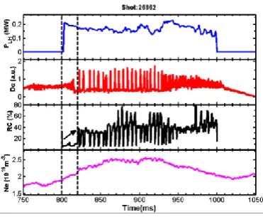
In shot #26862, the distance from the last closed flux surface (LCFS) to the PAM launcher mouth was 11.5 cm at the mid-plane. Fig. 3 is the time evolution of the coupled LH power, the average RC, the Dαsignal that shows the ELM behavior and the line integrated density. H-mode is triggered 20 ms after the LH power is applied, when the density reaches 2.1×10¹⁹ m-3. 700 kW of NBI
power is injected between t = 500 ms and t = 1000 ms.
Fig. 3. LH coupling of shot #26862.
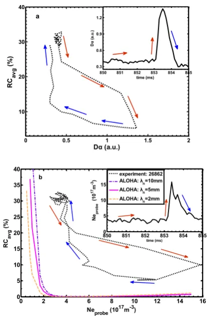
Fig. 4. RC versus the amplitude of the Dαsignal during one ELM (a) and versus the electron density measured on Langmuir probes on the launcher compared with calculation of ALOHA code for three different density decay lengths (b).
3.2. Coupling effect on local gas puffing
The local gas injection was found to be crucial in this experiment for increasing the local electron density at the launcher, since the plasma-launcher gap was always very large (usually more than 10 cm). The gas dosing was controlled by opening the valve during short intervals. This timing of the gas puffs is indicated in Fig. 5. The coupled LH power, RC, the Dα signal showing the ELM behavior and the density measured by a Langmuir probe at the antenna mouth are shown in the figure. The timing of the gas puffs are indicated by dashed vertical lines.
Fig. 5. LH coupling on gas injection, shot #27095
According to Fig. 5, an increase in ELM-frequency (at around t = 740 ms and 850 ms) can be observed. The reflection coefficient decreases typically 10 ms after the gas puff is switched on. In this discharge, the average RC decreases to 8% following the gas puffs.
3.3. Coupling optimization
In the first coupling experiments, 200-500kW LH power was coupled to H-mode plasmas via PAM antenna. Coupling optimization such as local gas puffing, plasma position control, antenna position set, and also plasma parameters changing were carried out in the experiments, decreasing RC to 10%.
Following the first experimental campaign in 2015, a number of modifications on the LH system and on the plasma control system were carried out in order to increase the coupled LH power. A piece of shorter flexible waveguide was changed in order to reduce transmission line losses and the RF measurements at the directional couplers were improved to get better reliability of forward and reflected power measurements in each module. On the plasma control system side, the divertor coil currents could be better controlled so as to maintain a smaller plasma-launcher gap during the H-mode phase. These modifications all had a significant effect on the LH power injection capability.
In the experiments carried out in June 2016 and May 2017, the plasma-launcher gap could be controlled at a smaller value during the H-mode phase, allowing lower fraction of reflected power to the LH launcher. The coupled LH power has thus reached 900 kW in H-mode and 1 MW in L-mode plasmas without any local gas injection [14].
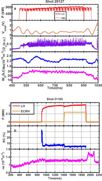
One H-mode discharge with NBI + LH is shown in Fig. 6 (a). The H-mode is triggered when the LH power is applied, and the H-mode is then sustained throughout the duration of the LH power. Fig. 6 (b) shows that the coupled power reached 1MW/1s with really low average RC. The density was constant during the LH power injection. The RC was a little high for the first several ms (~30%). This is mainly because of the plasma radial
0 0.5 1 1.5 2
10 20 30 40 Dα (a.u.) RC av g (%)
850 851 852 853 854 855 0.3 0.6 0.9 1.2 time (ms) D α ( a.u .) a
0 2 4 6 8 10 12 14 16
0 5 10 15 20 25 30 35 40
Neprobe (1017m-3)
RC
av
g
(%)
8500 851 852 853 854 855 5
10 15
time (ms)
N
eprobe
(1
0
17m -3)
experiment: 26862
ALOHA: λn=10mm
ALOHA: λn=5mm
ALOHA: λn=2mm
b 0 100 200 Shot:27095 PLH (kW) 20 40 60 80 RC ( % ) 0 0.5 1 1.5 Dα (a.u.)
550 600 650 700 750 800 850 900 950
drift impacted by the LH power injection. Then RC maintained a low level about 7%, and dropped to 4% after Electron Cyclotron Resonance Heating (ECRH) injected, indicating that the ECRH injection can benefit LH coupling. Local gas injection was not systematically used in these discharges, since the reflected power level was sufficiently low event at a smaller gap (~2.5 cm) without any local gas puffing.
Fig. 6. 900kW LH power coupled in H-mode plasmas, shot
#29127 (a) and 1MW in L-mode, shot # 31165 (b)
3.4. ELMs mitigation by LH power
The effect of LH power on the H-mode pedestal was investigated in these experiments, in particular the effect on the ELM frequency and ELM amplitude [15]. The results indicate an effect on the ELM behavior, i.e. increase in ELM frequency and decrease in ELM amplitude during LH power modulations [14], when the LH power is larger than ~ 300 kW. Fig. 7 is the time evolution of shot #27141, showing ELM modification during LH injection, including coupled LH power (a), local gas puffing signal (b), ELM behavior, as seen on ion saturation current (c) and plasma radiation (d), ELM frequency (e). The mitigation effect with LH waves was found to be sensitive to plasma parameters and there appears to be a minimum density, ne ~ 2.5×10¹⁹ m-3, above which the mitigation effect occurs. An increase of the pedestal turbulence measured by Doppler reflectometry could also be observed, which suggests
that an enhancement of the particle transport due to pedestal turbulence could be the cause of the ELM mitigation [14]. Similar effect was previously observed during supersonic molecular beam injection (SMBI) in HL-2A [16]. It appears that LH power injection can produce a comparable increase of the ELM frequency, as was also observed in EAST [17].
Fig. 7. ELMs mitigation by LH power injection, shot #27141.
4 RF heating system of HL-2M
A new tokamak device called HL-2M is being constructed in SWIP. The RF heating system including LHCD and ECRH system are developed. HL-2M will dispose of a 4 MW LHCD system and an 8 MW ECRH system, both of which are currently under installation.
4.1. LHCD system
The main parameters of the LHCD system on HL-2M are 3.7 GHz frequency, 4 MW power and 3 s duration. 2 MW wave source would be constructed for the first step with a 4 MW power capacity Full Active Multijunction (FAM) antenna. For the wave source, Four TH2103C1 klystrons are ready located in the heating hall of HL-2M. All of the auxiliary equipments are also ready for the klystron operation test, which will be started at early Jun 2017. There are 8 transmission lines in the system, about 30 m length each. Part of the transmission components such as power combiner, absorption load and the ceramic window have been tested since the high power test bed was built in 2015. The antenna is designed in FAM structure and the peak parallel refractive index n//0 is 2.25. TE10 to TE30 mode converters are designed for the antenna to divide the power in three parts equally in ploidal direction. As a result, There are 192 active grills (6×32) facing to the plasma, with passive ones at each
side.
0 450 900
Shot:29127
P (
kW)
0 1 2
Vloop
(V
)
0 0.5 1
Dα
(a
.u
.)
1.8 2.2 2.6
N
e(
10
19m -3)
450 550 650 750 850 950 1050 10
20 30
WE
(kJ)
Time(ms) LH NBI a
0 0.5 1
Shot:31165
P (MW
)
10 20 30 40
RC (
%
)
200 400 600 800 1000 1200 1400 1600 1800 2000 2200 0.6
1 1.4 1.8
ne (
10
19m -3)
Time(ms) LH
ECRH
Fig. 8. LHCD system layout of HL-2M.
Fig. 8 shows the layout of the LHCD system. The smaller klystrons in the figure have not been installed yet and the bigger ones are ready.
4.2. ECRH system
The ECRH system takes 105/140 GHz frequency, second harmonic injection to the plasma on HL-2M. the ECRH system includes eight gyrotrons (1 MW /3 s each), two of them can be operated at dual-frequency (140 GHz and 105 GHz), other six gyrotrons operated at single-frequency 105HGz. Fig. 9 shows the layout of the ECRH system. There are eight transmission lines, about 40 m length each. Corrugated circular waveguides (Ø = 63.5 mm ) are applied in the transmission lines to keep the wave HE11 propagation mode. The transmission lines
are pumped to 10-3 Pa level to avoid arcing. Three ports in the east of HL-2M, one equatorial port and two upper ports situated at the same vacuum segment, were allocated for ECRH launchers, corresponding to three different structure launchers, one 2×3 structure 6 MW
equatorial launcher, one 1×2 structure 2 MW upper
launcher and one 1×1 structure 1 MW upper launcher.
All of them can realize real-time feedback control in poloidal direction. For example, the response time of the equatorial launcher, which has been manufactured and tested in 2016, could reach 45ms for full scan range. One can note that the total power is less than the power for launching. It is because the three antennas would not be operated at the same time. A switch will be installed in the transmission line, guiding the power to different line in different shot as wish. Up to now, six gyrotrons, four transmission lines and one antenna is ready, including the auxiliary equipments.
Fig. 9. ECRH system layout of HL-2M.
5 Summary and conclusions
A new 3.7 GHz LHCD system was developed and applied on HL-2A, in which a new passive-active multijunction (PAM) launcher was successfully used in H-mode experiments for the first time. The LH power was generated from 4 TH2103A klystrons, operated in a new way, and transmitted to the antenna by eight transmission lines, with a transmission efficiency more than 80%. In the applying experiments, coupling optimization in H-mode plasmas was carried out. Coupling effect of ELMs and local gas puffing at the antenna mouth was investigated. It was found that the RC was higher during the ELM-rise than that of after the ELM-crash in the experiments, with same trend but higher RC than that of calculation result via ALOHA code. The local gas puffing at the antenna mouth was found beneficial for the LH coupling in H-mode plasmas with large gap. The optimization was successful since the coupled LH power reached 900 kW/400 ms in H-mode and 1 MW/ 1 s in L-H-mode plasmas. The LH power was found triggering and maintaining H-mode when the plasma was heated by 800 kW of Neutral Beam Injection (NBI) power. It was also found that the LH power can mitigate ELMs in the H-mode plasmas. The experiments indicates that the PAM launcher is a viable concept for high performance scenarios, the LH power can be coupled at large plasma-launcher gap, and assist in triggering and sustaining H-modes. In addition, LHCD and ECRH system of HL-2M tokamak was briefly introduced. There would be a 4 MW LHCD system and an 8 MW ECRH system on HL-2M. Parts of the two systems have been installed and tested.
Acknowledgments
Supply group. This work was carried out within the framework of the Associated Laboratory in the field of fusion between CEA/IRFM and SWIP.
This work is also supported by the domestic ITER project of China (No. 2011GB104000, No. 2014GB102000), funded by Ministry of Science and Technology (MOST) and the Natural Science Foundation of China (NSFC) project (No. 11575054, No. 11261140327), funded by NSFC.
References
1. P. Bonoli, Physics of Plasmas 21 (2014) 061508
2. G.T. Hoang et al, Nucl. Fusion 49 (2009) 075001
3. Ph. Bibet et al, Nucl. Fusion 35 (1995) 1213
4. F. Mirizzi et al, Fusion Eng. Des. 74 (2005) 237
5. V. Pericoli Ridolfini et al, Nucl. Fusion 45 (2005) 1085
6. D. Guilhem et al, Fusion Eng. Des. 86 (2011) 279
7. A. Ekedahl et al., Nucl. Fusion 50 (2010) 112002
8. Lu Bo et al., Journal of the Korean Physical Society 65 (2014) 1243
9. A. Ekedahl et al., Plasma Phys. Control. Fusion 51 (2009) 044001
10. F.K. Liu et al., Nucl. Fusion 55 (2015) 123022
11. J. Hillairet et al, Nucl. Fusion 50 (2010) 125010
12. X.Y. Bai et al., Proc. 42nd EPS Conference on Plasma Physics, Lisbon (2015), paper P5.137
13. V. Petrzilka et al., Plasma Phys. Control. Fusion 54 (2012) 074005
14. X.R. Duan et al., 26th IAEA Fusion Energy Conference (2016), paper OV/4-4
15. G.L. Xiao et al. This conference poster, A-24,
16. W.W. Xiao et al., Nucl. Fusion 52 (2012) 114027