Issue 2, October 1987
AT&T SYSTEM
MAINTENANCE
25
All Rights Reserved Printed in USA
TO ORDER COPIES OF THIS DOCUMENT REFER TO DOCUMENT NUMBER 555-520-105.
Contact: Your AT&T sales representative or
Call: 800-432-6600, Monday to Friday between 7:30 am and 6:00 EST, or
Write: AT&T Customer Information Center 2855 North Franklin Road
PO. Box 19901
Indianapolis, Indiana 46219
Every effort was made to ensure that the information in this document was complete and accurate at the time of printing. However, information is subject to change. This document will be reissued periodically to incorporate changes.
Maintenance Manual Prepared by System 25
Document Development Group and the AT&T Documentation
Do not open the fan assembly or remove rear cabinet cover before unplugging the cabinet from the electrical outlet. Wait at least five minutes after unplugging the power cord before removing the rear cover or power supply. The AT&T System 25 cabinets are not user serviceable. Some voltages inside the cabinets are hazardous. This equipment is to be serviced only by qualified technicians.
CUSTOMER WARNING
The Installation and Test Manual and the Maintenance Manual are designed for use by qualified service technicians only. Technician qualification includes completion of an AT&T hands-on instructor-led course covering installation and maintenance for this product. The use of these documents by anyone else might void the warranty.
AT&T SYSTEM 25
This telephone equipment is registered with the Federal Communications Commission (FCC) in accordance with Part 68 of its Rules. In compliance with the Rules, be advised of the following:
MEANS OF CONNECTION
Connection of this telephone e q u i p m e n t t o the nationwide telecommunications network shall be through a standard network interface USOC RJ21X jack. Connection to private line network channels requires USOC RJ2GX jack for tie lines or USOC RJ21X jack for off-premises station lines. These can be ordered from your telephone company.
NOTIFICATION TO THE TELEPHONE COMPANY
If the system is to be connected to off-premises stations (OPSs), you must notify the telephone company of the OPS class of service, OL13C, and the service order code, 9.0F.
Upon the request of the telephone company, inform them of the following:
— The Public Switched Network “lines” and the Private “lines” to which you will connect the telephone equipment.
—The telephone equipment’s “registration number” and “ringer equivalence number” (REN) from the label on the equipment.
— For each jack, provide the sequence in which lines are to be connected; the type lines and the facility interface code and the ringer equivalence number by position, when applicable.
This telephone equipment should not be used on coin telephone lines. Connection to party line service is subject to state tariffs.
REPAIR INSTRUCTIONS
If you experience trouble with this telephone equipment, contact the AT&T Business Customer Service Center on 1-800-242-2121. The telephone company may ask that you disconnect this equipment from the network until the problem has been corrected or until you are sure that this equipment is not malfunctioning.
RIGHTS OF
If your telephone
THE TELEPHONE COMPANY
equipment causes harm to the telephone network, the telephone company may discontinue your service temporarily. If possible, they will notify you in advance. But if advance notice isn’t practical, you will be notified as soon as possible. You will be informed of your right to file a complaint with the FCC.
Your telephone company may make changes in its facilities, equipment, operations, or procedures that could affect the proper functioning of your equipment. If they do, you will be notified in advance to give you an opportunity to maintain uninterrupted telephone service. The voice terminals described in this manual are compatible with inductively coupled hearing aids as prescribed by the FCC.
HEARING AID COMPATIBILITY
Registration Number AS593M-71565-MF-E
Ringer Equivalence 0.5A
Network Interface RJ21X or RJ2GX
PRIVATE LINE SERVICE
Service Order Code 9.0F
Facility Interface Code
ŽTie Lines TL31M
•Off-Premises Stations OL13C
FCC WARNING STATEMENT
Federal Communications Commission (FCC) Rules require that you be notified of the following:
● This equipment generates, uses, and can radiate radio frequency energy
and, if not installed and used in accordance with the instruction manual, may cause interference to radio communications.
● It has been tested and found to comply with the limits for a Class A
computing device pursuant to Subpart J of Part 15 of FCC Rules, which are designed to provide reasonable protection against such interference when operated in a commercial environment.
● Operation of this equipment in a residential area is likely to cause
INTRODUCTION 1-1
Organization 1-2
Equipment Needed 1-3
Assumption 1-3
Precautions 1-4
GENERAL MAINTENANCE INFORMATION System Errors and Alarms
Error Log
Emergency Transfer
Alarm and Status Indicators Switches and Test Points System Administration Terminal Maintenance Tests
2-1
2-2
2-2
2-3
2-3
2-4
2-4
2-5
SYSTEM HARDWARE Overview
Digital Switch
Station Interconnect Panel Trunk Access Equipment Terminal Equipment Wiring
Emergency Transfer Unit
3-1
3-1
3-3
3-3
3-5 3-7
3-7
Common Control and Switching Network 3-8
Common Control 3-10
Switching Network 3-16
SYSTEM SOFTWARE General
Switched Services Software Administrative Software Maintenance Software Memory Allocation Real-Time Constraints Software Partitioning Memory Circuit Pack Call Processor Circuit Pack TDM Bus
Port Circuit Packs
Step-By-Step Call Description
4-1 4-1 4-1 4-1 4-2 4-2 4-3 4-3 4-4 4-4 4-5 4-5 4-7 MAINTENANCE STRATEGY General Procedures
Total System Failures Port Problems
Common Control Problems
Station, Wiring, and Trunk Problems Automatic Maintenance Tests Maintenance Failure 5-1 5-3 5-3 5-3 5-4 5-4 5-5 5-5
ERROR LOG 6-1
Accessing the Error Log From the SAT 6-3
Error Log Dictionary 6-5
-ii-Setting up the DTU 7-1
Saving Translations 7-2
Verifying Translations 7-3
Restoring Translations
7-4CLEARING SYSTEM-DETECTED TROUBLES General Trouble-Clearing Techniques Consulting Error Log
Reseating and Replacing Circuit Packs Removing and Restoring Power Restarting the System
Interpreting Circuit Pack LEDs Clearing Specific System Troubles Complete System Failure
Common Control Trouble Circuit Pack Trouble
Frontplane Ribbon Connector Trouble Power Supply Trouble
Fan Assembly Trouble Overheating Trouble
Backplane and Cabinet Trouble Emergency Transfer Unit Trouble
8-1
8-1
8-1
8-1 8-3
8-4
8-8
8-9
8-9
8-9
8-11 8-12
8-12 8-17
8-18
8-18
8-26
CLEARING USER-REPORTED TROUBLES 9-1
Administration Equipment Troubles 9-1
Time-Keeping Troubles 9-2
Voice Terminal and Wiring Troubles 9-2
Voice Transmission Troubles 9-3
Outgoing Trunk Problems Incoming Trunk Problems
Error Log Interpretation: Loop Start Trunks Error Log Interpretation: Ground Start
Trunks
DID Trunks Troubles
Special Port Circuit Options for Stations and Trunks
Data Line Troubles
Multiple or Undiagnosable Troubles
9-5
9-6
9-6
9-7 9-8
9-9
9-11
9-13
REFERENCE DOCUMENTATION 10-1
ABBREVIATIONS AND ACRONYMS 11-1
GLOSSARY 12-1
INDEX 13-1
-iv-Figure 3-1. Figure 3-2. Figure 3-3. Figure 3-4. Figure 3-5. Figure 3-6. Figure 3-7. Figure 3-8. Figure 3-9. Figure 3-10. Figure 3-11. Figure 3-12. Figure 3-13. Figure 3-14. Figure 3-15. Figure 3-16. Figure 3-17. Figure 3-18. Figure 3-19. Figure 3-20.
System 25 Block Diagram
Typical Station Interconnect Panel (SIP) Connections
Trunk Access Equipment Connections System 25 Digital Switch
Call Processor [ZTN82 (V1) or ZTN128 (V2)] Circuitry
Memory [ZTN81 (V1) or ZTN127 (V2)] Circuitry
TDM Bus Time Slot Generation (Not a Timing Diagram)
TDM Bus Diagram—3-Cabinet System Equipment Connected to System 25 By
Call Processor and Port Circuit Packs
Port Circuit Pack Common Circuitry Unique Ground Start Trunk (ZTN76)
Circuitry
Unique Loop Start Trunk (ZTN77) Circuitry
Unique Tip Ring Line (ZTN78) Circuitry Unique ATL Line (ZTN79) Circuitry Unique Data Line (TN726) Circuitry Unique MET Line (TN735) Circuitry Unique Analog Line (TN742) Circuitry Unique DID Trunk (TN753) Circuitry Unique Tie Trunk (TN760B) Circuitry Tie Trunk (TN760B) Circuit Pack Option
Figure 3-22. Figure 3-23. Figure 3-24.
Figure 4-1.
Figure 5-1.
Figure 8-1. Figure 8-2. Figure 8-3.
Figure 8-4.
Circuitry 3-50
Service Circuit (ZTN85) 3-53
Tone Detector (TN748) Circuit 3-55
Pooled Modem (TN758) Circuit 3-57
System Software Partitioning 4-6
Response to System 25 Trouble Report 5-2
AC Power Schematic 8-15
System Cabinet Backplane 8-19
TDM Signal Designations On Cabinet
Backplane 8-21
Power Designations On Cabinet
Backplane 8-22
-vi-Table 3-A. Table 3-B.
Table 3-C.
Table 8-A.
Table 8-B. Table 8-C.
Table 9-A.
Table 9-B.
TDM Bus Time Slots
TN760B Option Switch Settings and Administration
Signaling Type Summary
Displayed SAT Messages During Cold or Warm Restart
Circuit Pack Voltages—Symptoms 25-Pair Connector to Backplane
Designations
Station/Trunk/Special Port Circuit Board Options
Applicable Actions for Circuit Board Options
3-18
3-47 3-48
8-6 8-13
8-24
9-10
This manual provides the information necessary for monitoring, testing, and maintaining AT&T System 25 (Release 1 Version 1 and Release 1 Version 2). The modular self-testing capabilities of the system allow most maintenance to be reduced to simple procedures.
This issue replaces all previous issues of this manual. This manual is reissued to include changes in System 25 maintenance strategy that enhance product safety and to make minor corrections in the previous issue.
This manual replaces the AT&T System 25 Maintenance Manual (555-500-105). This manual includes information on Version 1 (V1) and Version 2 (V2). V2 is primarily a software upgrade that provides the following:
● ● ● ● ●
Enhanced Data Services
STARLAN NETWORK Access
Switched Loop Attendant Console
Virtual Facilities
Miscellaneous Changes/Enhancements.
Required hardware for V2 includes a ZTN128 Processor circuit pack and a ZTN127 Memory circuit pack. A ZTN84 STARLAN Interface circuit pack and a switched loop attendant console are optional.
The maintenance procedures include:
● ● ● ● ●
Observation of alarm conditions;
Analysis of error messages and test results;
Performance of restoration procedures;
Replacement of system components; and
Performance of tests.
This manual is intended for use by a maintenance technician dispatched to a System 25 site in response to an alarm or a user trouble report. The technician must have completed the Tier 1 training course (T-335).
Each installed System 25 has a customer-designated System Administrator. The Administration and Implementation Manuals for your system describe the administrator’s functions. The maintenance technician should work closely with the System Administrator.
Organization
This manual is divided into 13 sections. The remaining sections are as follows:
● Section 2. General Maintenance Information— Provides an overview of alarms, maintenance concepts, equipment, and basic procedures.
● Section 3. System Hardware— Describes the principal components of the system, and provides detailed information on the switching network and all circuit packs (CPs) supported by the system.
● Section 4. System Software— Describes the system software resources including switched services software, administration software, and maintenance software.
● Section 5. Maintenance Strategy— Provides an overview of the maintenance process.
● Section 6. Error Log— Presents the format for error records and examples of error messages with explanations.
● Section 7. Operating the Digital Tape Unit— Provides operating instructions for the digital tape recorder to save and restore translations.
● Section 8. Clearing System-Detected Troubles— Provides general trouble-clearing techniques and procedures for clearing specific system troubles.
● Section 9. Clearing User-Reported Troubles— Describes user complaints and provides procedures for clearing them.
● Section 10. Reference Documentation— Provides a list of other System 25 documentation that may be valuable to the maintenance technician.
● Section 11. Abbreviations and Acronyms— Provides a list of abbreviations and acronyms used in System 25 documentation.
● Section 13. Index— Provides an alphabetical listing of principal subjects covered in this manual.
Equipment Needed
The following tools and equipment should be taken by the maintenance technician on any System 25 service call:
● EIA breakout box
● Digital voltmeter (KS-20599 or equivalent)
● Modular cord breakout box
● 110-type punchdown tool (AT 8762D or equivalent)
● Dracon TS21 or equivalent touch-tone test set
● Assorted flat-head screwdrivers
● Assorted Phillips-head screwdrivers
● Long-nosed pliers
● Regular pliers
● Wrist grounding strap
● Model DC4 Digital Tape Unit, with 355A adapter and a D8W cord (Comcode 404079429)
● Administration terminal (TI 703KSR or equivalent), with 355A adapter (Comcode 404079436).
An oscilloscope is not needed for the Tier 1 maintenance procedures provided in this manual.
Assumption
The information provided in this manual assumes that the system was initially installed and tested in accordance with the Installation and Test Manual (555-520-100).
Precautions
Electromagnetic fields radiating from the system cabinets may generate noise in other communications equipment. The technician must be sure that all cabinet panels and covers are securely in place after performing maintenance.
WARNING: Electrostatic discharge can destroy or severely damage
integrated circuits or CPs.
The maintenance technician MUST ALWAYS WEAR A WRIST GROUNDING
STRAP when handling CPs. The cord must be attached to the grounding block at the back of the cabinet. Damage to integrated circuits via electrostatic discharge may not be immediately apparent.
The primary maintenance objective is to detect, report, and clear troubles as quickly as possible with minimum disruption to normal service. Periodic system self-tests, automatic software diagnostic programs, and fault detection hardware are several of the maintenance tools used to achieve this objective. The system design allows most troubles to be isolated to a replaceable unit.
The System 25 hardware is maintained as a group of independent units (that is, maintenance objects). Each object is normally a separately replaceable unit. Examples include circuit packs (CPs), power supplies, fan assemblies, the Digital Tape Unit, AC Power Distribution Unit, voice terminals, lines, and trunks.
There are two general categories of troubles in system maintenance:
● System-Detected Errors
● User-Reported Troubles.
For system-detected errors, a light-emitting diode (LED) on the Attendant Console is automatically lighted if the error qualifies as an “alarm.” This is a serious error. Most alarms are also indicated by LEDs on system CPs.
User-reported troubles usually result from service problems at individual voice and data terminals and are often related to alarmed conditions.
Error records and alarms are retired either automatically or manually. After a trouble or error has been cleared, the system retests the previously faulty area within a variable time interval. When the error is no longer detected, the error message, and alarm if applicable, is retired. Maintenance personnel may choose to retire error records and alarms manually after a problem has been fixed by entering commands at the System Administration Terminal (SAT). Using the SAT, error records can be accessed, listed, and removed. Certain errors may not be removed. On the other hand, some alarms must be cleared manually. After the error messages have been removed from the error tables, the Attendant Alarm LED (and red CP LEDs) will go dark—
unless the trouble recurs.
System Errors and Alarms
When a system maintenance object begins to fail periodic testing, the system automatically generates an error record. Depending on severity, the record is stored in one of three tables in the error log.
The three tables are:
● Permanent System Alarms: These are failures that cause degradation of service and require immediate attention. These alarms will light the Alarm LED on the Attendant Console and are stored in the Error Log Permanent System Alarm table. This type of alarm also lights a red LED on an associated CP. The LED, when lighted, is a visual signal that service is required.
● Transient System Errors: These are potential failures that may cause degradation of service, although they do not light the Alarm LED on the Attendant Console. Transient System Errors are errors that have not yet been verified by system self-tests, and/or have not reached the level of a Permanent System Alarm.
If a Transient System Error is verified or reaches a certain threshold level of severity, it is reclassified as a Permanent System Alarm, and the Alarm LED on the Attendant Console lights. Transient system errors are stored in the Transient System Error table. The system stores up to 40 Permanent System Alarms and Transient System Errors in their respective tables in the error log.
● Most Recent System Errors: These are the ten most recent errors recorded by the system, regardless of their severity. They do not light the Alarm LED on the Attendant Console, unless they escalate to a Permanent System Alarm.
Error Log
The three error tables can be displayed on the System Administration Terminal (SAT). The error tables are very useful in diagnosing and analyzing problems, particularly when the problem has not caused an alarm or when alarms cannot be retired by replacement of maintenance objects.
Emergency Transfer
System 25 has emergency transfer capability in case of total system outage. Emergency transfer connects preassigned single-line voice terminals directly to trunks that are connected directly to the CO, bypassing the System 25. Emergency transfer is invoked by loss of ac power or by any failure of the system that prevents it from processing calls.
Alarm and Status Indicators
Maintenance-related LED indicators are provided on the following equipment:
● Attendant Console: A green Alarm LED is provided to indicate the
presence of a Permanent System Alarm. The LED flashes with each new alarm. The attendant can press the associated button to cause the LED to light steadily.
● Circuit Packs (CPs): LEDs are provided on the front edge of the CPs.
The LEDs are visible when the front cover of the cabinet is removed. When lighted, these LEDs indicate the status of the CP as follows:
● Port CPs:
— Red—” On” several seconds during power up and test, “Off” with test pass, and “On” if fault in CP or associated trunk is detected.
— Green—” On” indicates call resource available (port capable of processing calls).
— Yellow—” On” indicates a call in progress, “Off” when not in use.
— No LEDs Lighted—CP is not translated.
● Memory CP—Red status LED—’’On” several seconds during power up and test, “Off” with test pass. After test pass, “On” if fault in CP is detected.
● Service Circuit CP—Same as port CPs except yellow LED flashes (that is, flashes when busy). Steady “Off” indicates a CP problem. Steady “On” indicates a tone receiver is being used.
● Call Processor CP—This CP has only a green LED that flashes, except during test. “Off” or “On” steady indicates a problem.
Refer to “Clearing System-Detected Troubles—Interpreting Circuit Pack LEDs” in Section 8 for additional information.
● Power Supply: The cabinet power supply has a green LED that, when lighted, indicates normal power operation.
Switches and Test Points
The power switch on the back of the cabinet controls cabinet ac power and should be left in the “On” position (1=“On”), except when otherwise indicated. The system has no other field accessible switches, fuses, or circuit breakers. The power supply contains its own fuses, but these are not field replaceable.
Newer models have voltage test points located on the upper right corner at the front of the cabinet.
Older models have test points on the backplane behind the rear cover.
These test points are factory use only! Under no circumstances should the
rear cover be removed to provide access to the test points unless the power cord has first been unplugged.
System Administration Terminal
Maintenance Tests
There are two classes of automatic maintenance tests: periodic and demand.
Periodic tests are run automatically at fixed intervals on a specific schedule and do not affect service.
Demand tests are run by the system when it detects a need for them. Demand tests include the tests that are required only when trouble occurs. Some of the demand tests may be disruptive to system operation. Maintenance personnel cannot initiate any of these automatic tests.
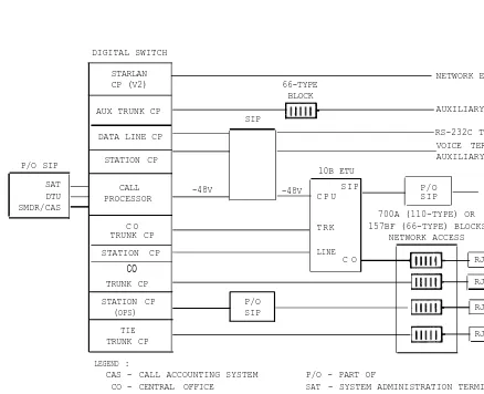
Overview
Figure 3-1 is a block diagram of the major components of System 25. The major hardware components of the system are:
● Digital Switch
● Station Interconnect Panel (SIP)
● Trunk Access Equipment (TAE)-includes 700A [110-type or 66-type (157BF)] Connector Blocks and Network Access Facilities
● Terminal Equipment
● Wiring
● Emergency Transfer Unit (ETU) *
● Digital Tape Unit *
● Common Control and Switching Network
● System Administration Terminal (SAT) *
● SMDR/Call Accounting System Output Device. *
* Optional Equipment
P/O SIP
SAT DTU SMDR/CAS
DIGITAL SWITCH
STARLAN
CP (V2) 66-TYPE NETWORK EXPANSION UNIT
BLOCK
AUX TRUNK CP AUXILIARY EQUIPMENT
SIP
DATA LINE CP RS-232C TERMINALS
VOICE TERMINALS, ADJUNCTS,
STATION CP AUXILIARY EQUIPMENT
10B ETU
CALL -48V
PROCESSOR -48V C P U
SIP P/O
SIP POWER FAILURETERMINALS
700A (110-TYPE) OR 157BF (66-TYPE) BLOCKS
NETWORK ACCESS C O
TRUNK CP TRK
STATION CP
C O RJ21X
CO
TRUNK CP RJ21X
STATION CP P/O CO
(OPS) SIP RJ21X
LINE
TIE RJ2GX
TRUNK CP
LEGEND : CAS
CO DTU ETU OPS
-CALL ACCOUNTING SYSTEM P/O - PART OF
CENTRAL OFFICE SAT - SYSTEM ADMINISTRATION TERMINAL DIGITAL TAPE UNIT SIP - STATION INTERCONNECT PANEL EMERGENCY TRANSFER UNIT SMDR - STATION MESSAGE DETAIL RECORDING OFF-PREMISES STATION
Figure 3-1. System 25 Block Diagram
Digital Switch
System 25 consists of up to 3 separate cabinets, each equipped with 12 universal slots for circuit packs (CPs). Each cabinet has its own power supply and fan assembly for cooling. No auxiliary equipment or customer-provided equipment is located in the cabinets.
The Common Control circuitry (Call Processor, Memory, and Service Circuit) is located in Cabinet 1. Other CPs can be located in any slot in any cabinet, but certain rules are suggested (see Reference Manual). All CPs are replaceable from the front of the cabinet upon removal of the front cover.
An address plug inserted into the header on the cabinet’s backplane (lower center portion) designates the cabinet number. When plugged into slot #5, the cabinet is translated as Cabinet #1, slot #6 = Cabinet 2, and slot #7 = Cabinet #3.
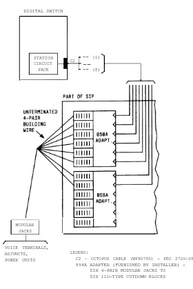
Station Interconnect Panel
The Station Interconnect Panel (SIP) (Figure 3-2) provides connectivity between the digital switch and station equipment via the building wiring. Peripheral equipment is also generally connected to the system through the SIP.
The SIP consists of a group of 617A panels and associated adapters. The adapters support building wiring circuits that are either cutdown or modular.
Octopus cables connect the system cabinets to the SIP. Adapters that can
be mounted on the SIP are as follows:
● Z210A—Six 4-pair modular jacks to six 4-pair modular jacks
DIGITAL SWITCH
STATION
C2 -- (1)
CIRCUIT _ _
PACK -- (8)
MODULAR JACKS
VOICE TERMINALS, ADJUNCTS, POWER UNITS
LEGEND:
C2 – OCTOPUS CABLE (WP90780) - PEC 2720-05P 858A ADAPTER (FURNISHED BY INSTALLER)
-SIX 4-PAIR MODULAR JACKS TO SIX 11O-TYPE CUTDOWN BLOCKS
Figure 3-2. Typical Station Interconnect Panel (SIP) Connections
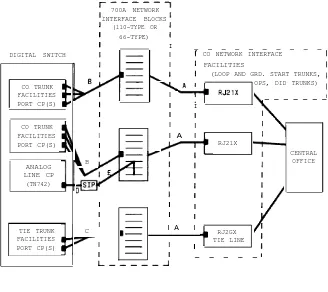
Trunk Access Equipment
700A NETWORK INTERFACE BLOCKS
(110-TYPE OR 66-TYPE)
I
DIGITAL SWITCH I CO NETWORK INTERFACE
I FACILITIES
_ _ _ _ _ _ _ _ _ _
(LOOP AND GRD. START TRUNKS,
CO TRUNK OPS, DID TRUNKS)
FACILITIES I
PORT CP(S) I I — — — — — — —
I I
CO TRUNK I I
FACILITIES I I A I
PORT CP(S) I RJ21X
CENTRAL
B OFFICE
ANALOG LINE CP
(TN742)
I I I
I I I
TIE TRUNK C I I A I RJ2GX
FACILITIES
I I TIE LINE
PORT CP(S) I
I I — — — — —
LEGEND: A B C OPS SIP D E *
-SINGLE-ENDED 25-PAIR CONNECTOR CABLE (A25D)*
3 TO 1 SPLITTER CONNECTORIZED CABLE (OR6016) - PEC 2720-06X 2 TO 1 SPLITTER CONNECTORIZED CABLE (OR6015) - PEC 2720-05X OFF-PREMISES STATION
STATION INTERCONNECT PANEL*
OCTOPUS CABLE (WP90780) - PEC 2720-05P INSIDE WIRE*
FURNISHED BY INSTALLER
Figure 3-3. Trunk Access Equipment Connections
Terminal Equipment
System 25 terminal equipment includes various voice terminals,
Asynchronous Data Units (ADUs), data terminals, attendant consoles, and auxiliary equipment. System 25 supports three types of voice terminals: 7300H series, Single-Line [Tip & Ring (touch-tone or rotary*)], and MET (Multibutton Electronic Telephone). Each type of voice terminal must be connected to a compatible port CP.
ADUs provide the interface between the system and data equipment connected to the Data Line Circuit (TN726) ports. Single-line and 7300 series multiline voice terminals can also be connected to ADUs along with data equipment. Separate wire pairs in the ADU provide voice terminal connectivity back to the digital switch via the SIP. At the SIP, an adapter is used to separate the voice and data leads for connection to their respective system ports.
Wiring
The wiring plan is consistent with the Small Business Distribution System. The system uses 4-pair cables (24 AWG or 26 AWG) and cords as well as modular connectors and adapters. Various building wiring arrangements are supported, including new wiring, reuse, and modular.
Emergency Transfer Unit
The Emergency Transfer Unit (ETU) supports five power failure transfer stations and a Direct Inward Dialing (DID) make busy function. A System 25 installation can have up to four ETUs. The ETU is activated if ac power fails or if the system stops functioning.
Digital Tape Unit
The Model DC4 Digital Tape Unit (DTU) is required on all maintenance calls. It is used to save translations if the system fails. Translations should be saved on both the original and the backup tape cassette on a maintenance call (see Section 7 “Operating the Digital Tape Unit”).
Common Control and Switching Network
Figure 3-4 shows the System 25 digital switch.
The basic switch hardware consists of the following:
● Common Control
— Memory Bus
— Call Processor CP
— Memory CP
● Switching Network
— TDM (Time Division Multiplex) Bus
— Port Circuits
— System Resources
MEMORY BUS
COMMON
CONTROL CALL
PROCESSOR MEMORY
TDM BUS
SWITCHING
NETWORK PORT CIRCUITS
SERVICE CIRCUIT
TONE DETECTOR
POOLED MODEM
SYSTEM RESOURCES TRUNKS,
VOICE TERMINALS, DATA TERMINALS
Common Control
The Common Control circuitry consists of the Call Processor [ZTN82 (V1) or ZTN128 (V2)] and Memory [ZTN81 (V1) or ZTN127 (V2)] circuit packs and associated memory bus.
Memory Bus
The memory bus is a 60-wire (including grounds), 39-bit (16-data, 23-address), 6-MHz frontplane flat ribbon cable.
Call Processor Circuit Pack [ZTN82 (V1) or ZTN128 (V2)]
The Call Processor runs the system feature software. It is powered from the backplane by +5 and -5 volts. It also draws -48 volts from the backplane to drive the Emergency Transfer Unit. Each system must include one Call Processor CP. The Call Processor circuitry, as shown in Figure 3-5, includes:
● Microprocessor
● Memory management
● On-board memory
● EIA channels
● Network controller
● Clock
● Frontplane interface
● Reset circuitry
● Bus error circuitry
● Interrupt circuitry
●Emergency Transfer Unit Control.
SERIAL CHANNEL
1
TO EMERGENCY
EIA CHANNELS TRANSFER UNIT ( RS-232C ) (ETU)
INTERRUPT CIRCUITRY SERIAL -48V DC CHANNEL 4 ETU CONTROL BUS
ERROR MICROPROCESSOR EIA CIRCUITRY
EIA
(68010) CONTROL CONTROL
RESET CIRCUITRY PROCESSOR FRONT BUS TO MEMORY PLANE CIRCUIT INTERFACE PACK VIA
(BUS FRONT PLANE BUFFERS) BUS MEMORY
MANAGEMENT
READ TIME OF
NETWORK DAY
TDM CONTROLLER CLOCK
BUS S A K I
LEADS
BUFFERS
BATTERY ONLY
MEMORY ( 64K )
RANDOM ACCESS MEMORY (80K) SERIAL SERIAL CHANNEL CHANNEL 2 3 +5V DC (POWER F A I L
DETECT)
Microprocessor: A 68010 16-bit microprocessor that executes call processing and data processing features. This includes all maintenance, administration, testing, and reporting software.
Memory Management: Memory management separates the on-board
Random Access Memory (RAM) into 1024 memory pages of 256 bytes each. Each page is read and write protected, generates bus errors when violated, and each is recappable allowing data areas to remain contiguous.
On-Board Memory: On-board memory includes 64 K bytes of Read Only
Memory (ROM) containing the power-up tests and the switch operating system. In addition, there are 80 K bytes of protected RAM containing writable data storage for call processing. The RAM is backed up by an on-board trickle-charge battery that maintains memory contents for up to 2 months. Of the 80 K RAM, 24 K is dedicated to translation data. The remainder is dedicated to call status data and the operating system message queues.
EIA Channels: Four asynchronous RS-232C EIA ports (1-4) are included to permit communication with an administration terminal, a maintenance terminal, a Station Message Detail Recording (SMDR) device, and a Digital Tape Unit.
Network Controller: The network controller transmits control channel
messages between the Call Processor and the port circuits over the TDM bus. The controller also monitors system clocks.
The controller includes an 8-bit microprocessor that acts as a throttle, passing messages between the Call Processor and the port board microprocessors.
All uplink messages from the port circuits are checked for consistency and passed to the common control. The controller is the distribution control point for all downlink control messages. It continuously scans, over the TDM bus, the port circuit microprocessors for sanity and activity. External RAM associated with this microprocessor stores control channel information and port related information.
The controller consists of bus buffers and a System And Control Interface (SAKI). The bus buffers provide the interface between the TDM bus and the on-board data buses to the SAKI. The SAKI receives and transmits control messages on the first five time slots on the TDM bus. The microprocessor communicates with the SAKI and external RAM over the address and data bus.
Clock: A clock provides time of day information in seconds, minutes, and hours and the date to the 68010 microprocessor. The clock automatically adjusts for leap years. An on-board battery backs up the clock so that accurate time is maintained even when the system power is off.
Frontplane Interface: Dedicated buffers provide an interface to the
frontplane, which is the communication path to the Memory circuit pack.
Reset Circuitry: The processor is automatically reset when power is turned on, when the +5 volt power supply drops below 4.5 volts (after it returns to +5 volts), or when the network controller detects the processor insane. The processor can also reset the network controller when it detects the network controller insane.
Bus Error Circuitry: Bus errors suspend the processor from executing code. Bus errors are generated when memory management detects illegal reads or writes to RAM, when the processor attempts to access circuit packs or chips not physically present, or when the network controller detects the processor insane.
Interrupt Circuitry: Interrupts are prioritized into seven levels, of which the highest (level 7) is non-maskable. The interrupts are:
Interrupt Level
AC Fail 7
Work cycle 6
Off board 5
Two EIA ports 4
Other two EIA ports 3
Off board 2
Off board 1
Memory Circuit Pack [ZTN81 (V1) or ZTN127 (V2)]
The Memory circuit pack provides for the storage of software associated with system operation. This software includes call and administration processing and other related programs. The circuit pack is powered from the backplane by +5 volts. Each system must include one Memory circuit pack. The Memory circuit pack circuitry (Figure 3-6) includes:
● Address and data buffers
● ROM array
● ROM select
● Timing and control logic
● Built-in TDM bus termination resistors.
Address and Data Buffers: The address and data buffers interface the
Memory circuit pack to the address and data lines on the frontplane.
ROM Array: The memory array consists of 16 ROM devices of 32 K, 8-bit bytes each, for a total capacity of 512 K ROM. The ROMs are organized into pairs allowing the Call Processor to access 16-bit words.
ROM Select: The memory selects the proper pair of ROMs according to address information.
Timing and Control Logic: This circuit controls the access speed of the ROM (no wait states) by returning a Data Transfer Acknowledge signal at the proper time.
3-14
SYSTEM HARDWARE
TERMINATOR RESISTORS ROM
SELECT
FRONT PANEL MEMORY BUS (TO CALL PROCESSOR CIRCUIT
PACK )
ADDRESS
AND ROM
DATA BUFFERS TIMING ARRAY
AND CONTROL
TO TDM BUS
Switching Network
System 25 uses distributed processing techniques to provide switched voice and data services. The switch operates at 64 Kbps. The switching network consists of the following:
● Time Division Multiplex (TDM) bus
● Port Circuits
● System Resources.
The TDM bus connects the intelligent ports to the Common Control circuit packs and other ports through the network control circuit. The system resource circuits provide tone sources, receivers, detectors, and pooled modems. The intelligent ports connect external communications facilities to the TDM bus.
TDM Bus
The TDM bus consists of two groups of eight signal leads and five control leads, each with matching grounds. The port circuit packs place digitized voice [pulse code modulated (PCM)] signals on the bus.
The bus operates at 2.048 MHz. The system framing pulse is 8 kHz. This provides 256 time slots (0-255) on the bus. The time slots are 488 ns wide. Time slots are generated as shown in Figure 3-7. The first five time slots are used for communications between the Common Control, the intelligent port, and resource circuit packs. Two time slots are required for each 2-party conversation. Each party transmits (talks) on one time slot and receives (listens) on another. Only five parties are allowed in a conference. During a conference connection, each member of the conference transmits on an individual time slot while receiving on as many as four other time slots. The actual switch capacity is 115 simultaneous 2-party conversations.
Table 3-A shows the allocation of the 256 time slots. Five are used for system control, 15 for tones, 235 for call processing, and 1 is not used.
SYSTEM FRAME 8 KHZ
(125 MICROSECONDS)
488 NANOSECONDS I
SYSTEM CLOCK _ _ _ _ _ _ _
2.048 MHZ
TIME SLOTS O 4 5 255 0
256 TIME SLOTS
1 2 3
Table 3-A. TDM Bus Time Slots
TIME SLOT NO.
00 thru 04 05 06 07 08 09 10 11 12 13 14 15 16 17 18 19 20 thru 254 255 FUNCTION Control (5) -Tones-(15) Dial Tone Busy Tone Reorder Tone Ringback Tone Data-Null Voice-Null Music 697 Hz* 770 Hz* 852 Hz* 941 Hz* 1209 Hz* 1336 Hz* 1447 Hz* 1637 Hz* Call Processing (235) Not Used (1)
* These tones are used to generate touch-tone signals.
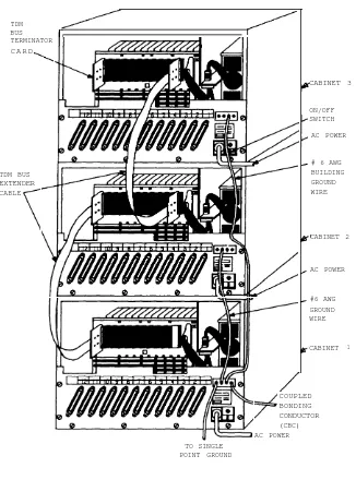
Physical Characteristics: The TDM bus is an 8-bit bus. The bus snakes continuously between cabinets in a multicabinet system as shown in Figure 3-8. The total length is about 9 feet for a 3-cabinet system. The bus is driven from any of the circuit packs in the cabinets. Similarly, a signal on the bus can be received by any circuit pack.
Within a cabinet, the bus is printed on one side of the circuit pack carrier backplane, and the other side is solid ground. Ribbon cables are used to cable the TDM bus between cabinets in a multicabinet system.
Electrical Characteristics: The TDM bus is an unbalanced, low-characteristic impedance transmission line. Paths printed over a ground plane on the carriers and the flat ribbon cables between carriers maintain this impedance level over the full length of the bus.
TDM BUS TERMINATOR C A R D
CABINET 3
ON/OFF SWITCH
AC POWER
# 6 AWG BUILDING GROUND WIRE TDM BUS
EXTENDER CABLE
CABINET 2
AC POWER
#6 AWG GROUND WIRE
CABINET 1
COUPLED BONDING CONDUCTOR (CBC) AC POWER TO SINGLE
POINT GROUND
Figure 3-8. TDM Bus DIagram—3-Cabinet System
Port Circuits
The following port circuit packs provide the link between trunks and external equipment and the TDM bus:
● Ground Start Trunk (ZTN76)
● Loop Start Trunk (ZTN77)
● Tip Ring Line (ZTN78).
● ATL Line (ZTN79)
● Data Line (TN726)
● MET Line (TN735)
● Analog Line (TN742)
● DID Trunk (TN753)
● Tie Trunk (TN760B)
● Auxiliary Trunk (TN763)
● STARLAN Interface (ZTN84) (V2)
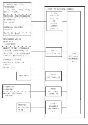
Figure 3-9 shows the equipment types that can be connected to the digital switch by the Call Processor and port circuit packs. Figure 3-9 shows only overall concepts. Some arrangements require auxiliary power and/or adapters. See the Installation and Test Manual (555-520-100) or Reference
SINGLE-LINE VOICE TERMINALS
(420, 500, 2500, 2514, 2554, 7101A) RECORDED ANNOUNCEMENTS — — — — — — — — _ _ _ _ _ _ _ _ DICTATION EQUIPMENT _ _ _ _ _ _ _ _ EXTERNAL ALERTING DEVICES _ _ _ _ _ _ _ _ MUSIC-ON-HOLD _ _ _ _ _ _ _ _ MULTILINE VOICE TERMINALS (7300H-TYPE)
DIRECT TRUNK ATTENDANT CONSOLE (7305H02B) OR SWITCHED LOOP ATTENDANT CONSOLE (7305H04C) ATTENDANT DIRECT EXTENSION SELECTOR CONSOLE (MODEL 23A1) _ _ _ _ _ _ _ _ MET SETS _ _ _ _ _ _ _ _ DICTATION EQUIPMENT PAGING EQUIPMENT (PagePac)
PART OF DIGITAL SWITCH
ZTN78 TIP RING LINE CP OR TN742 ANALOG LINE CP ZTN79
ATL LINE CP TIME DIVISION MULTIPLEX
BUS
TN735 MET LINE CP
TN763 AUXILIARY TRUNK CP NETWORK EXTENSION UNIT ZTN84 STARLAN INTERFACE C P
Figure 3-9. Equipment Connected to System 25 By Call Processor and Port Circuit Packs (Sheet 1 of 3)
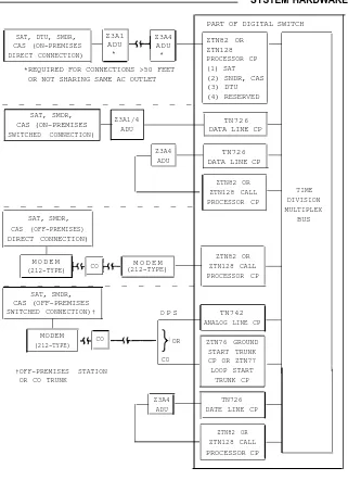
SAT, DTU, SMDR, CAS (ON-PREMISES DIRECT CONNECTION) Z3A1 ADU * Z3A4 ADU *
*REQUIRED FOR CONNECTIONS >50 FEET OR NOT SHARING SAME AC OUTLET
ZTN82 OR ZTN128 PROCESSOR CP (1) SAT (2) SNDR, CAS (3) DTU (4) RESERVED
_ _ _ _ _ _ _ _ _ _ _ _
SAT, SMDR,
CAS (ON-PREMISES Z3A1/4 SWITCHED CONNECTION) ADU
TN726 DATA LINE CP
Z3A4 ADU
TN726 DATA LINE CP
_ _ _ _ _ _ _ _ _ _ _ _
SAT, SMDR, CAS (OFF-PREMISES) DIRECT CONNECTION)
M O D E M
(212-TYPE) CO
M O D E M (212-TYPE)
_ _ _ _ _ _ _ _ _ _ _ _
SAT, SMDR, CAS (OFF-PREMISES
SWITCHED CONNECTION)† O P S TN742
ANALOG LINE CP
MODEM
(212-TYPE) CO OR
CO †OFF-PREMISES STATION
OR CO TRUNK
Z3A4 ADU
PART OF DIGITAL SWITCH
ZTN82 OR
ZTN128 CALL TIME PROCESSOR CP DIVISION
MULTIPLEX BUS ZTN82 OR ZTN128 CALL PROCESSOR CP ZTN76 GROUND START TRUNK CP OR ZTN77 LOOP START
TRUNK CP
TN726 DATE LINE CP
ZTN82 OR ZTN128 CALL PROCESSOR CP
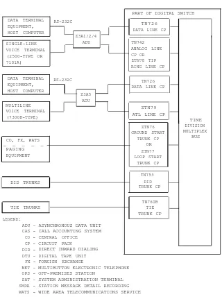
DATA TERMINAL RS-232C EQUIPMENT,
HOST COMPUTER
Z3A1/2/4
T N 7 2 6 DATA LINE CP
SINGLE-LINE ADU
VOICE TERMINAL (2500-TYPE OR 7101A)
DATA TERMINAL RS-232C EQUIPMENT, HOST COMPUTER Z3A5 ADU MULTILINE VOICE TERMINAL (7300H-TYPE) ZTN79 ATL LINE CP
TIME DIVISION MULTIPLEX
BUS CO, FX, WATS
_ _ _ _ _ PAGING EQUIPMENT DID TRUNKS TRUNK CP TIE TRUNKS TN760B TIE TRUNK CP LEGEND: ADU – CAS CO CP DID -DTU – FX -MET – OPS -SAT – SMDR WATS
-ASYNCHRONOUS DATA UNIT CALL ACCOUNTING SYSTEM CENTRAL OFFICE CIRCUIT PACK
DIRECT INWARD DIALING DIGITAL TAPE UNIT FOREIGN EXCHANGE
PART OF DIGITAL SWITCH
TN742 ANALOG LINE CP OR ZTN78 TIP RING LINE CP
TN726 DATA LINE CP
ZTN76 GROUND START TRUNK CP OR ZTN77 LOOP START TRUNK CP TN753 DID
MULTIBUTTON ELECTRONIC TELEPHONE OFF-PREMISES STATION
SYSTEM ADMINISTRATION TERMINAL STATION MESSAGE DETAIL RECORDING WIDE AREA TELECOMMUNICATIONS SERVICE
Figure 3-9. Equipment Connected to System 25 By the Call Processor and Port Circuit Packs (Sheet 3 of 3)
Eight port circuits are provided on most port circuit packs. The MET Line, Tie Trunk, and Auxiliary Trunk CPs each contain four port circuits. The port circuits provide an interface between terminals/trunks and the TDM bus. The STARLAN Interface CP (V2) is unique. It provides one interface (port) to a Network Extension Unit (NEU) and four connections to the TDM bus.
The number of port circuit packs required varies per customer requirements and equipment configuration.
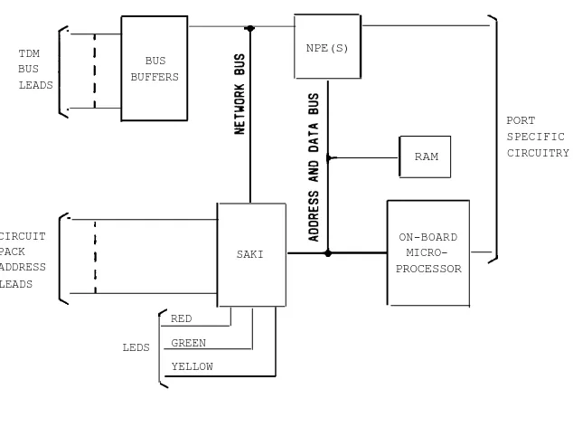
Each of the System 25 port circuit packs contain a number of common elements (see Figure 3-10), such as:
● Bus buffers
● Sanity And Control Interface (SAKI)
● On-board microprocessor with external Random Access Memory (RAM)
● One or more Network Processing Elements (NPEs)
TDM BUS LEADS
NPE(S)
RAM
CIRCUIT PACK ADDRESS LEADS
BUS BUFFERS
SAKI
RED
LEDS GREEN YELLOW
ON-BOARD MICRO-PROCESSOR
PORT SPECIFIC CIRCUITRY
Figure 3-10. Port Circuit Pack Common Circuitry
BUS Buffers: The bus buffers are the digital interface between the backplane TDM bus wires (system bus) and the on-board circuitry (data bus). They also receive and distribute clock and frame signals.
SAKI (Sanity And Control Interface): The SAKI is the control interface between the Common Control that sends information via the network control circuit down the TDM buses and the board circuitry controlled by the on-board microprocessor. The SAKI receives control information (down-link messages) on the first five time slots and, as requested by the on-board microprocessor, transmits control information (up-link messages) on these same time slots.
The SAKI also performs the following functions:
●Identifies the circuit pack to the Common Control (location and vintage)
● Controls status indicator light-emitting diodes (LEDs)—red (failure), green (translated), and yellow (circuit busy)
● Initiates power-on startup procedures
● Checks the on-board microprocessor for sanity and causes reinitialization if problems occur
● Takes NPEs out of service under control of the on-board microprocessor
●Resets the protocol handler on the ATL Line circuit pack
● Generates the STARLAN NETWORK address on the STARLAN Interface circuit pack
● Resets the OATMEAL devices on the STARLAN Interface circuit pack
● Takes the whole circuit pack out of service on command from the Common Control or when it determines that on-board interference is present in the control time slots.
NPEs (Network Processing Element): Each port circuit pack contains one or two NPEs. The Analog Line, ATL Line, Tip Ring Line, Data Line, Ground Start, Loop Start, and DID Trunk circuit packs contain two NPEs. The MET Line, Auxiliary Trunk, and Tie Trunk circuit packs contain one NPE.
The NPEs perform switching network functions for the port circuits. Under control of the on-board microprocessor, an NPE can connect a port circuit to any one of the TDM bus time slots. More specifically, it allows a port circuit to talk on one time slot and listen to the same time slot (NPE sidetone) and on up to four other time slots at the same time. In 2-wire circuits that provide their own sidetone, the NPE sidetone is not used.
Circuit Pack Address Leads: Seven leads (BA0-BA6) are tied to
corresponding logic levels to uniquely identify each CP slot in the system, including multiple cabinet systems. The logic values on leads BA4 and BA5 are used to identify the cabinet (Cabinet 1, 2, or 3) and are tied by the cabinet address plugs to either +5 V dc or ground, as appropriate. Lead BA6 is tied to ground.
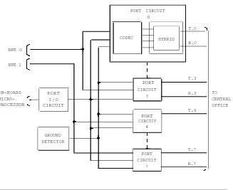
Ground Start Trunk (ZTN76)
The Ground Start Trunk circuit pack interfaces eight central office trunks and the TDM bus. Figure 3-11 shows the following Ground Start Trunk unique circuitry:
● Ground detector circuit
● Port Input/Output (I/O) circuit
● Eight port circuits.
Ground Detector Circuit: The ground detector circuit determines if ground has been applied to the tip lead for incoming seizure. It also senses tip ground on outgoing seizure indicating dial tone is present. One ground sensor is used for each port circuit. Input for the ground sensor comes from the port circuit as an analog current to the -48 V dc supply. The ground sensor’s output is a port control point to the port I/O circuit.
Port I/O Circuit: This circuit consists of bus expanders for communication between the on-board microprocessor and the port circuits. It receives commands from the on-board microprocessor and distributes them to the individual port circuits. It also accesses the port circuit scan points and passes the information to the on-board microprocessor.
Port Circuits: The eight port circuits are identical. Each port circuit consists of a coder/decoder (codec), hybrid circuit, line transformer, relay driver, and surge protection circuit.
The codec is a 4-wire circuit that converts the NPEs digital output to an analog signal. Likewise, it converts the analog signal from a central office trunk to a Pulse Code Modulation (PCM) data signal to the NPE. The hybrid circuit converts the codec 4-wire analog signal to a 2-wire analog signal that is connected to the central office trunk by the line transformer.
NPE O
NPE 1
PORT
ON-BOARD
MICRO-PORT I/O CIRCUIT PROCESSOR
PORT CIRCUIT
4
GROUND DETECTOR
PORT CIRCUIT 0
CODEC HYBRID T.O
R.O
T.3
CIRCUIT
3 R.3
T.4
T.7 PORT
CIRCUIT
7 R.7
TO CENTRAL OFFICE
Figure 3-11. Unique Ground Start Trunk (ZTN76) Circuitry
Loop Start Trunk (ZTN77)
The Loop Start Trunk circuit pack interfaces eight central office loop start trunks and the TDM bus. Figure 3-12 shows the following Loop Start Trunk unique circuitry:
● Port Input/Output (I/O) circuit
● Eight port circuits.
Port I/O Circuit: This circuit consists of bus expanders for communication between the on-board microprocessor and the port circuits. It receives commands from the on-board microprocessor and distributes them to the individual port circuits. It also accesses the port circuit scan points and passes the information to the on-board microprocessor.
Port Circuits: The eight port circuits are identical. Each port circuit consists of a codec, hybrid circuit, line transformer, relay driver, and surge protection circuit.
The codec is a 4-wire circuit that converts the NPEs output to an analog signal. Likewise, it converts the analog signal from a central office trunk to a PCM data signal to the NPE. The hybrid circuit converts the codec 4-wire analog signal to a 2-wire analog signal that is connected to the central office trunk by the line transformer.
PORT CIRCUIT 0
CODEC HYBRID
NPE O
NPE 1
ON-BOARD
MICRO-PORT
PORT I/O PROCESSOR CIRCUIT
T.O
R.O
T.3
CIRCUIT
3 R.3
T.4 PORT
CIRCUIT
4 R.4
T.7 PORT
CIRCUIT
7 R.7
TO CENTRAL OFFICE
Figure 3-12. Unique Loop Start Trunk (ZTN77) Circuitry
Tip Ring Line (ZTN78)
The Tip Ring Line circuit pack interfaces eight analog tip and ring voice terminal lines (single-line voice terminals) and the TDM bus. Figure 3-13 shows the following Tip and Ring Line unique circuitry:
● Ringing application circuit
● Port Input/Output (I/O) circuit
● –48 V to -24 V Power Conditioner
● Eight port circuits.
Ringing Application Circuit: This circuit receives ringing voltage from the power supply. It monitors ringing voltage and current and generates signals to the on-board microprocessor indicating zero ringing voltage and current. It also detects when a terminal user has lifted the receiver during ringing, preventing the application of ringing to the terminal’s handset receiver.
Port I/O Circuit: This circuit includes bus expanders connecting the on-board microprocessor and the port circuits. It receives commands from the on-board microprocessor and distributes them to the individual port circuits. It also accesses the port circuit scan points and passes the information to the on-board microprocessor.
-48 V To -24 V Power Conditioner: This circuit converts -48 V power from the power supply into a conditioned source of -24 V power for the electronic battery feed circuits.
Port Circuits: Each port circuit is identical. A port circuit consists of a coder/decoder (codec), hybrid circuit, battery feed circuit, and ring relay.
The codec is a 4-wire circuit that converts the NPE’s output to an analog signal. Likewise, it converts the analog signal from a central office trunk to a PCM data signal to the NPE. The hybrid circuit converts the codec 4-wire analog signal to a 2-wire analog signal that is connected to the central office trunk by the line transformer.
The battery feed circuit provides talking battery to the voice terminal. It also detects when a receiver is lifted, and provides the message waiting signal by periodically reducing the feed voltage to zero.
CODEC HYBRID ELECTRONICBATTERY
FEED
NPE O
NPE 1
ON-BOARD MICRO-PROCESSOR
CIRCUIT R.3 3
POWER SUPPLY
PORT I/O CIRCUIT
RINGING APPLICATION
CIRCUIT
-48V TO -24V POWER CONDITIONER
PORT CIRCUIT
0
T.O
R.O
T.3 PORT
T.4 PORT
CIRCUIT
4 R.4
T.7 PORT
CIRCUIT
7 R.7
TO ANALOG TIP/RING VOICE TERMINALS
Figure 3-13. Unique Tip Ring Line (ZTN78) Circuitry
ATL Line (ZTN79)
The ATL Line circuit pack interfaces eight hybrid voice terminal (7300H series) lines and the TDM bus. It terminates three pairs of wires from each terminal: analog voice pair, digital control pair, and power pair. Figure 3-14 shows the following ATL Line unique circuitry:
● Protocol handler
● Eight port circuits.
Protocol Handler: The 8-bit on-board microprocessor translates the control information in CCMS message format to the control information message format used by the 7300H series voice terminals. The protocol handler sends the messages to the terminals using transceivers located in the port circuits.
Port Circuits: Each port circuit is identical. A port circuit consists of an analog port, one-half of a transceiver, and an electronic power feed device.
The analog port circuit consists of a codec, a hybrid circuit, an isolation transformer, and associated power filtering circuitry. The codec and hybrid circuits perform the same function as the codec and hybrid circuits in the Analog Line circuit pack (TN742). The output of the hybrid circuit is connected to the primary of the isolation transformer. The secondary of the transformer is connected to the analog voice pair.
The transceiver interfaces the voice terminal pair to the protocol handler. The electronic power feed device provides -48 V dc on the power pair to the voice terminal. The device is polled by the on-board microprocessor, periodically and on demand, to test for an overcurrent or no-current condition.
NPE O ON-BOARD MICRO-PROCESSOR PXT.0 ELECTRONIC
POWER FEED PXR.0
PXT.1 ON-BOARD MICRO-PROCESSOR PROTOCOL HANDLER
PORT CIRCUIT PORT O
ANALOG PORT
CODEC HYBRID ISOLATION TRANSFORMER DATA TRANSCEIVER T.0 R.0 TXT.O TXR.O PXR.1 T.3 R.3 PORT TXT.3 CIRCUIT TXR.3 3 PXT.3 PXR.3 T.4 R.4 PORT TXT.4 CIRCUIT TXR.4 4 PXT.4
NPE 1 PXR.4
T . 7 R . 7 TXT.7 P O R T
CIRCUIT TXR.7 7 PXT.7 PXR.7 TO MULTILINE VOICE TERMINALS
Figure 3-14. Unique ATL Line (ZTN79) Circuitry
Data Line (TN726)
The Data Line circuit pack interfaces eight Asynchronous Data Units (ADUs) data devices and the TDM bus. The ADUs are typically, in turn, connected to RS-232C-type devices. Figure 3-15 shows the Data Line unique circuitry that includes:
● A bit clock
● Bus isolation
● Eight port circuits.
Bit Clock: The bit clock circuitry is used to provide the OATMEALs (Octal Asynchronous Terminal Mode Two EIA Asynchronous LSIs) with a clock frequency that is a multiple of each baud rate. In addition, the clock rate is divided down to 160 kHz. The 160 kHz is then compared to the system’s 160 kHz data clock and is phase-locked to the system clock. The phase-locked circuit is required for low-speed operation.
Bus Isolation: This portion of the circuit pack is used to isolate the microprocessor bus. Isolation is required because the realized bus load exceeds the maximum limit specified for this device, due to the large number of devices controlled by the NPE. The OATMEALs are isolated from the common bus structure.
Port Circuits: Each of the eight identical port circuits allows the connection of interface equipment having an RS-232C compatible serial interface to the switch. The circuit provides an asynchronous full-duplex subset of standard data speeds from 300 to 19,200 bps. Each port includes an Asynchronous Data Unit (ADU) to extend the serial communications link length and provide safe isolation. The ADU terminates to another ADU at the Customer-Provided Equipment (CPE). The distance between the digital switch and CPE is inversely proportional to the speed at which the link is run. See Reference
Manual (555-520-200) for details.
A PXT.0 PROTOCOL HANDLER ASYNCHRONOUS DATA UNIT (ADU) PXR.0 TXT.0 NPE 0 TXR.0 ON-BOARD MICROPROCESSOR NPE 1 BUS
ISOLATION A PORT
CIRCUIT 3 A PORT CIRCUIT 4 A PORT CIRCUIT 5 BIT CLOCK
PORT CIRCUIT O
(OATMEAL) A PORT CIRCUIT 1 A PORT CIRCUIT 2 I I I I I I I I I I I I I I I I I I I I I I I I I I I I I I I A PORT CIRCUIT 6
A PORT PXT.7
CIRCUIT PXR.7
7 TXT.7
TXR.7 TO ADUS
Figure 3-15. Unique Data Line (TN726) Circuitry
MET Line (7N735)
The MET Line circuit pack interfaces four Multibutton Electronic Telephone (MET) lines and the TDM bus. The MET Line unique circuitry consists of four port circuits as shown in Figure 3-16.
Port Circuits: The four port circuits are identical. Each port circuit consists of an analog port, a digital port, and an electronic power feed device.
The analog port circuit consists of a codec, a hybrid circuit, an electronic battery feed, and a power filter. The codec, hybrid circuit, and power filter perform the same function as in the Analog Line circuit pack (TN742). The electronic battery feed provides talking battery to the MET set. The electronic battery feed produces a controlled dc battery feed current for short and long loops and detects when a MET set user lifts a receiver.
The digital port circuit provides a full-duplex channel over two 2-wire pairs. All outgoing lamp (LT, LR) and incoming button depression (BT, BR) information is carried on these channels. Ringing and switchhook information is also sent over these channels.
ANALOG PORT
DIGITAL PORT
ELECTRONIC POWER FEED
ON-BOARD MICRO-PROCESSOR
NPE
PORT CIRCUIT
T.O R.O
BT.O
BR.O
LT.O LR.O
T.3 R.3
PORT CIRCUIT BT.3
3 BR.3
LT.3 LR.3
TO MET TERMINALS
Figure 3-16. Unique MET Line (TN735) Circuitry
Analog Line (lN742)
The Analog Line circuit pack interfaces eight analog voice terminal lines and the TDM bus. Figure 3-17 shows the following Analog Line unique circuitry:
● Ringing application circuit
● Port Input/Output (I/O) circuit
● Eight port circuits.
Ringing Application Circuit: This circuit receives ringing voltage from the power supply. It monitors ringing voltage and current, generates signals to the on-board microprocessor indicating zero ringing voltage and current, and detects a terminal user lifting the receiver during ringing. This prevents the application of ringing to the port circuit when a terminal user lifts the receiver during the ringing phase. Maintenance circuitry is also included. The maintenance circuitry detects when a terminal is connected to the port circuitry and checks for faults in the ringing application circuitry.
Port I/O Circuit: This circuit consists of bus expanders connecting the on-board microprocessor and the port circuits. It receives commands from the on-board microprocessor and distributes them to the individual port circuits. It also accesses the port circuit scan points and passes the information to the on-board microprocessor.
Port Circuits: The eight port circuits are identical. Each port circuit consists of a coder/decoder (codec), hybrid circuit, electronic battery feed circuit, ring relay, and overvoltage surge protection circuit.
The codec is a 4-wire circuit that converts the analog signal from a voice terminal to a PCM data signal. It converts an incoming PCM data signal from the NPEs to an analog signal. The hybrid circuit converts the 4-wire analog signal from the codec to a 2-wire analog signal that is connected to the analog line. Filtered power is provided for the codec and hybrid circuits.
The electronic battery feed circuit provides talking battery to the voice terminal. It also produces a controlled dc battery feed for short and long loops, detects when a receiver is lifted, and provides the message waiting signal by periodically turning off the feed voltage.
The ring relay provides the interface between the ringing application circuit and the port circuit. It causes ringing turn on and turn off.
Note: NPE 0 NPE 1 ON-BOARD MICRO-CODEC HYBRID ELECTRONIC BATTERY FEED PROCESSOR
The TN742 may be used instead of the ZTN78 Tip Ring circuit pack. The TN742 supports up to five bridged single-line voice terminals; however, only two may be off-hook at one time. The ZTN78 circuit pack does not support bridged terminals. In addition, the TN742 supports out-of-building, extended, and off-premises stations; the ZTN78 does not.
PORT CIRCUIT 0 OVERVOLTAGE PROTECTION PORT I I/O T.3 CIRCUIT PORT CIRCUIT 3 R.3 I I T.0 I I R.0 RINGING APPLICATION T.4 CIRCUIT PORT CIRCUIT 4 R.4 POWER I SUPPLY I I T.7 PORT CIRCUIT 7 R.7 TO ANALOG TIP/RING VOICE TERMINALS
Figure 3-17. Unique Analog Line (TN742) Circuitry
DID Trunk (TN753)
The DID Trunk circuit pack interfaces eight central office trunks arranged for Direct Inward Dialing (DID) and the TDM bus. Figure 3-18 shows the following DID Trunk unique circuitry:
● Port Input/Output (I/O) circuit
● Eight port circuits.
Port I/O Circuit: This circuit consists of bus expanders for communication between the on-board microprocessor and the port circuits. It receives commands from the on-board microprocessor and distributes them to the individual port circuits. It also accesses the port circuit scan points and passes the information to the on-board microprocessor.
Port Circuits: The eight port circuits are identical. Each port circuit consists of a codec, balance network, trunk interface unit, and loop termination circuit.
The codec is a 4-wire circuit that converts the NPE output to an analog signal. Likewise, it converts the analog signal from the central office (CO) to a PCM signal to the NPE.
The trunk interface unit contains a hybrid circuit, a 2-wire interface circuit, and control circuitry. The hybrid circuit converts the 4-wire analog signal from the codec to a 2-wire analog signal that is connected to the analog line by the 2-wire interface circuit. The control circuitry controls loop current, internal signal gain, terminating resistance, battery feed shutdown, and battery reversal. The circuit pack accepts both dial pulse and touch-tone signaling.
HYBRID
NPE 0
NPE 1
CIRCUIT
3 R.3
ON-BOARD
MICRO-PORT CIRCUIT 0
TRUNK INTERFACE
UNIT
CODEC
T.O
R.0
T.3 PORT
PORT I/O
CIRCUIT PORT T.4
PROCESSOR
CIRCUIT
4 R.4
T.7 PORT
TO CENTRAL OFFICE
CIRCUIT
7 R.7
Figure 3-18. Unique DID Trunk (TN753) Circuitry
Tie Trunk (TN760B)
The Tie Trunk circuit pack interfaces four 6-wire tie trunks and the TDM bus. Two tip and ring pairs form a 4-wire analog transmission line. An E and M pair is used for signaling. The T and R pair transmits analog signals from the circuit pack. The T1 and R1 pair receives analog signals from the tie trunk. The E and M pair are dc signaling leads used for call setup handshaking. The E lead receives signals from the tie trunk and the M lead provides signals from the circuit pack. The TN760B’s four port circuits support Type I, Type I Compatible, or Type V signaling. Incoming and outgoing trunks may be either automatic, immediate start, wink start, or delay dial. Figure 3-19 shows the following Tie Trunk unique circuitry:
● Ground detector circuit
● Port Input/Output (I/O) circuit
● Four port circuits.
Ground Detector Circuit: This circuit determines if a ground has been applied to the E lead. Ground detector inputs come from the port circuits as an analog current to the -48 V dc supply. Its output is a port control point to the port I/O circuit.
Port I/O Circuit: This circuit consists of bus expanders for communication between the on-board microprocessor and the port circuits. It receives commands from the on-board microprocessor and distributes them to the individual port circuits. It also accesses the port circuit scan points and passes the information to the on-board microprocessor.
Port Circuits: The port circuits are identical, except for port 3 where part of the E-lead maintenance circuit is located. Each port circuit consists of a codec with associated input and output line transformers, analog operational amplifiers, a power filter, loop-around transistors, port control comparators, a relay driver, an electronic power feed device, an E-lead test maintenance circuit, and surge protection circuits.
The loop-around transistors are under control of the port control comparators and provide a loop-around path for the signal for testing purposes. The relay driver buffers and inverts the relay drive signals from the port I/O circuit so that a logic high input operates the appropriate relay. The relays and electronic power feed device control the M-lead circuitry to provide the proper signaling handshake for call progress tones and dial pulse dialing.
The electronic feed device provides a -48 V dc current to the M-lead circuits. It also tests the M-lead circuits for opens or shorts and prevents uncontrolled operation during powerup. The E-lead test circuit provides a ground to the ground detector circuit for testing
provides lightning surge and power
T.0
NPE
ON-BOARD MICRO-PROCESSOR
purposes. The surge protection circuitry cross protection for the circuit pack.
R.0
PORT T1.0
CIRCUIT R1.0 0
PORT E.0
I/O M.0
CIRCUIT
GROUND
DETECTOR T.3
TO TIE TRUNKS R.3
PORT CIRCUIT
3
T1.3 R1.3 E.3 M.3
Figure 3-19. Unique Tie Trunk (TN760B) Circuitry
Various signaling formats (consists of a mode and a type) are available with the TN760B. The mode designates the electrical interface and the type designates the logical signaling used. For each port circuit, the mode is selected by option switch settings on the CP. Table 3-B lists the preferred signaling formats for
option switch settings.
likely-to-be encountered installation situations and The option switches are shown in Figure 3-20.
UNPROT.
PORT: 4 3 2 1
PROT. SMPLX SMPLX SMPLX SMPLX
PORT 4 PORT 3 PORT2 PORT 1
E&M E&M E&M E&M
Figure 3-20. Tie Trunk (TN760B) Circuit Pack Option Switches
Table 3-C summarizes control signals for each
the conditions signaling type.
present as the transmit and receive
Table 3-C. Signaling Type Summary
SIGNALING TRANSMIT RECEIVE
TYPE On-Hook Off-Hook On-Hook Off-Hook
I Std. grd bat open/bat (*) grd
I Compat. open/bat (*) grd grd open/bat (*)
V open grd open grd
* An open circuit is preferred over voltage.
Auxiliary Trunk (TN763)
The Auxiliary Trunk circuit pack interfaces four ports provided for customer-provided equipment (CPE) and the TDM bus. It is connected to the CPE by up to three pairs of wires. The transmission pair (T and R) carries voice signals and touch-tone control signals. T and R also provides a loop start seizure indication to the CPE. The seizure pair (SZ and SZ1) provides seizure indication to the CPE. The signal pair (S and S1) provides answer
![Figure 3-5.Call Processor [ZTN82 (V1) or ZTN128 (V2)] Circuitry](https://thumb-us.123doks.com/thumbv2/123dok_us/1194245.1149982/33.614.140.460.226.570/figure-call-processor-ztn-v-or-ztn-circuitry.webp)