555-722-140
Issue 1
June 2002
MERLIN MAGIX
®
Integrated System
Notice
Every effort has been made to ensure that the information in this guide is complete and accurate at the time of printing. Information, however, is subject to change. See Appendix A, “Customer Support Information,” in Feature
Referencefor important information.
Avaya Web Page
The world wide web home page for Avaya is http://www.avaya.com.
Preventing Toll Fraud
Toll Fraud is the unauthorized use of your telecommunications system by an unauthorized party (for example, a person who is not a corporate employee, agent, subcontractor, or working on your company's behalf). Be aware that there is a risk of toll fraud associated with your system and that, if toll fraud occurs, it can result in substantial additional charges for your telecommunications services.
Avaya Fraud Intervention
If you suspect that you are being victimized by toll fraud and you need technical assistance or support, call Technical Service Center’s Toll Fraud Intervention Hotline at 800 643-2353.
Providing Telecommunications Security
Telecommunications security of voice, data, and/or video communications is the prevention of any type of intrusion to, that is, either unauthorized or malicious access to or use of, your company's telecommunications equipment by some party.
Your company's “telecommunications equipment” includes both this Avaya product and any other voice/data/video equipment that could be accessed via this Avaya product (that is, “networked equipment”).
An “outside party” is anyone who is not a corporate employee, agent, subcontractor, or working on your company's behalf. Whereas, a “malicious party” is anyone, including someone who may be otherwise authorized, who accesses your telecommunications equipment with either malicious or mischievous intent.
Such intrusions may be either to/through synchronous (time multiplexed and/or circuit-based) or asynchronous (character-, message-, or packet-based) equipment or interfaces for reasons of:
• Utilization (of capabilities special to the accessed equipment)
• Theft (such as, of intellectual property, financial assets, or toll-facility access) • Eavesdropping (privacy invasions to humans)
• Mischief (troubling, but apparently innocuous, tampering)
• Harm (such as harmful tampering, data loss or alteration, regardless of motive or intent)
Be aware that there may be a risk of unauthorized or malicious intrusions associated with your system and/or its networked equipment. Also realize that, if such an intrusion should occur, it could result in a variety of losses to your company, including, but not limited to, human/data privacy, intellectual property, material assets, financial resources, labor costs, and/or legal costs.
All Rights Reserved November 2001
Copyright and Legal Notices
Sour Responsibility for Your Company's Telecommunications Security
The final responsibility for securing both this system and its networked equipment rests with you - an Avaya customer's system administrator, your telecommunications peers, and your managers. Base the fulfillment of your responsibility on acquired knowledge and resources from a variety of sources, including, but not limited to:
• Installation documents
• System administration documents • Security documents
• Hardware-/software-based security tools • Shared information between you and your peers • Telecommunications security experts
To prevent intrusions to your telecommunications equipment, you and your peers should carefully program and configure your:
• Avaya provided telecommunications system and their interfaces
• Avaya provided software applications, as well as their underlying hardware/software platforms and interfaces • Any other equipment networked to your Avaya products
Federal Communications Commission Statement
This equipment has been tested and found to comply with the limits for a Class A digital device, pursuant to Part 15 of the FCC Rules. These limits are designed to provide reasonable protection against harmful interference when the equipment is operated in a commercial environment. This equipment generates, uses, and can radiate radio frequency energy and, if not installed and used in accordance with the instruction manual, may cause harmful interference to radio communications. Operation of this equipment in a residential area is likely to cause harmful interference, in which case the user will be required to correct the interference at their own expense. For further FCC information, see Appendix A, “Customer Support Information,” in Feature Reference.
Part 68: Network Registration Number. This equipment is registered with the FCC in accordance with Part 68 of
the FCC Rules. See Appendix A, “Customer Support Information, “FCC Notification and Repair” section for registration numbers and more information regarding Part 68.
Part 68: Answer-Supervision Signaling. Allowing this equipment to be operated in a manner that does not
provide proper supervision signaling is in violation of Part 68 Rules. This equipment returns answer-supervision signals to the public switched network when:
• Answered by the called station • Answered by the attendant
• Routed to a recorded announcement that can be administered by the CPE user
This equipment returns answer-supervision signals on all DID calls forwarded back to the public switched telephone network. Permissible exceptions are:
• A call is unanswered • A busy tone is received • A reorder tone is received
Industry Canada (IC) Interference Information
NOTICE: This equipment meets the applicable Industry Canada Terminal Equipment Technical Specifications. This is confirmed by the registration number. The abbreviation, IC, before the registration number signifies that registration was performed based on a Declaration of Conformity indicating that Industry Canada technical specifications were met. It does not imply that Industry Canada approved the equipment.
Trademarks
5ESS, AUDIX, CONVERSANT, CentreVu, DEFINITY, Magic On Hold, MERLIN, MERLIN LEGEND, MERLIN MAGIX, MERLIN Mail, PARTNER, PassageWay, MLX-10, MLX-20L, MLX-28D, 6, 12, 12D, MLS-18D, MLS-34D, SYSTIMAX, TransTalk, and Voice Power are registered trademarks and 4ESS, Intuity, and ProLogix are trademarks of Avaya Inc. in the U.S. and other countries.
Acculink, ACCUNET, MEGACOM, MulitiQuest, MLX-5, MLX-5D, MLX-16DP, MLX-10D, MLX-10DP, and NetPROTECT are registered trademarks of AT&T.
Microsoft, Windows, Windows NT, and MS-DOS are registered trademarks of Microsoft Corporation. PSupra, Supra NC, StarSet, and Mirage are registered trademarks of Plantronics, Inc.
UNIX is a registered trademark of UNIX System Laboratories, Inc.
PagePac is a registered trademark and Powermate and Zonemate are trademarks of DRACON, a division of Harris Corporation.
Okidata is a registered trademark of Okidata Corporation. Pipeline is a trademark of Ascend Communications, Inc.
Intel and Pentium are registered trademarks of Intel Corporation. Apple and Macintosh are registered trademarks of Apple Computer, Inc. IBM is a registered trademark of International Business Machines, Inc. Novell and NetWare are registered trademarks of Novell Corporation. CLASS is a servicemark of Bellcore.
Ordering Information
For more information about Avaya documents, refer to the section entitled “Related Documents” in “About This Guide” in Feature Reference.
Support Telephone Number
In the continental U.S., Avaya provides a toll free customer helpline 24 hours a day. Call the Avaya Customer Care Center at 1 800 628-2888 or your Avaya authorized dealer if you need assistance when installing, programming, or using your system. Outside the continental U.S., contact your local Avaya authorized representative.
Warranty
Avaya provides a limited warranty on this product. Refer to “Limited Warranty and Limitation of Liability” in “Customer Support Information” in Feature Reference.
Obtaining Products
To learn more about Avaya products and to order products, contact Avaya Direct, the direct-market organization of Avaya Business Communications Systems. Access their web site at avaya.com/direct or call 800 426-2455.
Call: Avaya Publications Center
Voice 1 800 457-1235 International Voice 410 568-3680 Fax 1 800 457-1764 International Fax 410 891-0207
Write: GlobalWare Solutions 200 Ward Hill Avenue Haverhill, MA 01835 USA Attention: Avaya Account Management
Email: [email protected]
Safety
IMPORTANT SAFETY INSTRUCTIONS
The exclamation point in an equilateral triangle is intended to alert the user to the presence of important operating and maintenance (servicing) instructions in the literature accompanying the product.
When installing telephone equipment, always follow basic safety precautions to reduce the risk of fire, electrical shock, and injury to person, including:
■ Read and understand all instructions.
■ Follow all warnings and instructions marked on or packed with the product.
■ Never install telephone wiring during a lightning storm.
■ Never install a telephone jack in a wet location unless the jack is specifically designed for wet locations.
■ Never touch uninsulated telephone wires or terminals unless the telephone wiring has been disconnected at the network interface.
■ Use caution when installing or modifying telephone lines.
■ Use only Avaya Inc.-manufactured MERLIN MAGIX Integrated System circuit modules, carrier assemblies, and power units in the MERLIN MAGIX Integrated System control unit.
■ Use only Avaya Inc.-recommended/approved MERLIN MAGIX Integrated System accessories.
■ If equipment connected to the TDL telephone modules (412 LS-ID-TDL and 024 TDL), the MLX telephone modules (008 MLX, 408 GS/LS-MLX, 408 GS/LS-ID-MLX, and 016 MLX), or the ETR telephone module (016 ETR) is to be used for in-range out-of-building (IROB) applications, IROB protectors are required.
■ Do not install this product near water—for example, in a wet basement location.
■ Do not overload wall outlets, as this can result in the risk of fire or electrical shock.
■ The MERLIN MAGIX Integrated System is equipped with a 3-wire grounding-type plug with a third (grounding) pin. This plug will fit only into a grounding-type power outlet. This is a safety feature. If you are unable to insert the plug into the outlet, contact an electrician to replace the obsolete outlet. Do not defeat the safety purpose of the grounding plug.
■ The MERLIN MAGIX Integrated System requires a supplementary ground.
■ Do not attach the power supply cord to building surfaces. Do not allow anything to rest on the power cord. Do not locate this product where the cord will be abused by persons walking on it.
■ Slots and openings in the module housings are provided for ventilation. To protect this equipment from overheating, do not block these openings.
■ Never push objects of any kind into this product through module openings or expansion slots, as they may touch dangerous voltage points or short out parts, which could result in a risk of fire or electrical shock. Never spill liquid of any kind on this product.
■ Unplug the product from the wall outlet before cleaning. Use a damp cloth for cleaning. Do not use cleaners or aerosol cleaners.
■ Auxiliary equipment includes answering machines, alerts, modems, and fax machines. To connect one of these devices, you must first have a Multi-Function Module (MFM).
■ Do not operate telephones if chemical gas leakage is suspected in the area. Use telephones located in some other safe area to report the trouble.
!
WARNING:
!
To eliminate the risk of personal injury due to electrical shock, DO NOT attempt to install or remove an MFM from your MLX telephone. Opening or removing the module cover of your telephone may expose you to dangerous voltages.
ONLY an authorized technician or dealer representative shall install, set options, or repair an MFM.
System Programming Basics
Master Table of Contents
About This Guide
Intended Audience ...
vii
How to Use This Guide ...
vii
Terms and Conventions Used...
viii
Security ...
x
Related Documents...
xi
How to Comment on This Guide ...
xii
1
About System Programming
Overview ...
1-1
Types of Programming...
1-1
Methods of Programming...
1-2
About Programming Procedures...
1-3
Moving Among System Programming Screens ...
1-4
About Programming and Idle States ...
1-4
2
System Programming Console
Overview ...
2-1
4424LD+ and MLX-20L Console Components ...
2-4
Direct Station Selector (DSS)...
2-5
System Programming Console Buttons ...
2-7
Console Overlay...
2-9
Console and DSS Lights ...
2-11
Displaying the System Programming Menu from the Console...
2-12
3
About WinSPM
Overview ...
3-1
System Requirements...
3-2
Installing the WinSPM Software...
3-3
Setting Up your Desktop ...
3-5
Defining Your Password ...
3-8
Setting Up a Site ...
3-9
About the WinSPM Main Screen Options ...
3-17
Using View ...
3-18
Using Tools ...
3-18
Using Quick Access ...
3-19
WinSPM Help...
3-27
Using Standard SPM Mode ...
3-27
Basic System Management Procedures ...
3-31
Board Renumbering with the
System Programming Basics
Master List of Figures
2
System Programming Console
2-1
The 4424-LD+ Telephone . . . .
2-2
2-2
The MLX-20L Telephone . . . .
2-3
2-3
DSS4450 for 4400-Series Telephones . . . .
2-6
2-4
4424LD+ Display Buttons and Main Menu . . . .
2-7
2-5
MLX-20L Display Buttons and Main Menu . . . .
2-8
2-6
4424LD+ System Programming Console Overlay . . . .
2-10
2-7
MLX-20L System Programming Console Overlay . . . .
2-11
3
About WinSPM
3-1
WinSPM Main Screen . . . .
3-4
3-2
Direct Connection, PC Less Than 50 Feet Away . . . .
3-15
3-3
Connecting a Modem to a T/R Extension Jack . . . .
3-16
3-4
Connect to the MERLIN MAGIX Internal Modem from a Remote Location . .
3-17
System Programming Basics
Master List of Tables
1
About System Programming
1-1
Typefaces Used in Programming Procedures . . . .
1-3
2
System Programming Console
2-1
4424LD+ and MLX-20L Console Components . . . .
2-4
2-2
DSS 4450 Components . . . .
2-7
2-3
Fixed Display Buttons Functions . . . .
2-8
2-4
Description of Options in System Programming Menu . . . .
2-12
2-5
Selections to Return to the System Programming Menu . . . .
2-13
3
About WinSPM
3-1
Function of PC Keys in WinSPM . . . .
3-29
3-2
SPM Main Menu Options . . . .
3-30
Intended Audience
x
About This Guide
0The MERLIN MAGIX Integrated System is an advanced digital switching system that integrates voice and data communications features. Voice features include traditional telephone features, such as Transfer and Hold, and advanced features, such as Group Coverage, Direct Voice Mail, and Tandem Switching. Data features allow both voice and data to be transmitted over the same system wiring.
Intended Audience
0This book provides detailed information about system features, extension features, and system applications of the MERLIN MAGIX Integrated System. It is intended as a reference for anyone needing such information, including support personnel, sales representatives, System Managers, and account executives. It is also intended for technicians who are responsible for system installation, maintenance, and troubleshooting.
How to Use This Guide
0This guide has been designed to provide optimal assistance to you in completing the planning forms—for example:
1. Since some chapters and/or sections apply to one or another of the configurations (Key or Behind Switch, Hybrid/PBX, or data communications), these sections are clearly marked—for example, “Hybrid/PBX Only.” Also, you are alerted to proceed to the next appropriate section, or to skip chapters or sections that do not apply to your particular system. Proceed through this guide as appropriate.
2. A list of forms or information that will be needed for particular procedures appears at the beginning of each chapter and section.
Terms and Conventions Used
Since this guide assumes that you are familiar with the system, detailed information about equipment, features, and programming are not included. Refer to the following documentation for additional information:
■ Feature Reference gives procedural instructions for programming system features.
■ User and operator guides give procedural instructions for programming and using telephone features.
‘‘Related Documents,” later in this section, provides a complete list of system documentation, together with ordering information.
In the USA only, Avaya provides a toll free customer Helpline 24 hours a day. Call the Helpline at
1 800 628-2888 (consultation charges may apply), or contact your Avaya representative if you need assistance when installing, programming, or using your system.
Outside the USA, if you need assistance when installing, programming, or using your system,
contact your Avaya authorized representative.
Terms and Conventions Used
0The terms described here are used in preference to other, equally acceptable terms for describing communications systems.
Lines, Trunks, and Facilities
0Facility is a general term that designates a communications path between a telephone system and
the telephone company central office. Technically, a trunk connects a switch to a switch—for example, the MERLIN MAGIX Integrated System to the central office. Technically, a line is a loop-start facility or a communications path that does not connect switches—for example, an intercom line or a Centrex line. In actual usage, however, the terms line and trunk are often applied interchangeably. In this guide, we use line/trunk and lines/trunks to refer to facilities in general. Specifically, we refer to digital facilities. We also use specific terms such as Personal Line,
ground-start trunk, Direct Inward Dialing (DID) trunk, and so on. When you talk to personnel at your local
Terms and Conventions Used Some older terms have been replaced with newer terms, as follows:
Typographical Conventions
0Certain type fonts and styles act as visual cues to help you rapidly understand the information presented:
Old Term New Term
trunk module line/trunk module trunk jack line/trunk jack
station extension
station jack extension jack
analog data station modem data workstation digital data station terminal adapter workstation
7500B data station ISDN terminal adapter data workstation digital voice and analog data station MLX voice and modem data workstation analog data-only station modem data-only workstation
digital data-only station terminal adapter data-only workstation 7500B data-only station ISDN terminal adapter data-only workstation digital voice and digital data station MLX voice and terminal adapter workstation
MLX voice and 7500B data station MLX voice and ISDN terminal adapter data workstation
Convention Example
Italics or bold indicates emphasis. It is very important that you follow these steps.
WARNING: Do not remove modules from the carrier without following proper procedures. Italics also sets off special terms. The part of the headset that fits over one or
both ears is called a headpiece. Plain constant-width type indicates text that
appears on the telephone display or PC screen, as well as characters you dial at the telephone or type at the PC.
Choose ExtProgfrom the display screen.
Security
Product Safety Advisories
0Throughout these documents, hazardous situations are indicated by an exclamation point inside a triangle and the word CAUTION or WARNING.
WARNING:
Warning indicates the presence of a hazard that could cause death or severe personal injury if the hazard is not avoided.
CAUTION:
Caution indicates the presence of a hazard that could cause minor personal injury or property damage if the hazard is not avoided.
Security
0Certain features of the system can be protected by passwords to prevent unauthorized users from abusing the system. You should assign passwords wherever possible and limit distribution of such passwords to three or fewer people.
Nondisplaying authorization codes and telephone numbers provide another layer of security. For more information, see Appendix A, “Customer Support Information in the Feature Reference.”
Throughout this guide, toll fraud security hazards are indicated by an exclamation point inside a triangle and the words SECURITY ALERT.
SECURITY ALERT:
Related Documents
Related Documents
0The documents listed in the following table are part of the MERLIN MAGIX documentation set. Within the continental United States, contact the Avaya Publications Center by calling
1 800 457-1235.
Document No. Title
System Documents:
555-722-110 Feature Reference
555-722-112 System Planning
555-722-113 System Planning Forms
555-722-119 System Manager’s Quick Reference
555-661-150 Network Reference
555-721-800 Customer CD-ROM:
Consists of System Manager’s Quick Reference, Feature Reference (PDF version), and Online Feature Reference tool (HTML version).
Telephone User Support:
555-710-123 (U.S. English)
4400/4400D Telephone User’s Guide
555-710-123FRC (Canadian French)
4400/4400D Telephone User’s Guide
555-710-127 (U.S. English)
4406D+, 4412D+, 4424D+, and 4424LD+ Telephone User’s Guide
555-710-127FRC (Canadian French)
4406D+, 4412D+, 4424D+, and 4424LD+ Telephone User’s Guide
555-660-122 MLX Display Telephone User’s Guide
555-630-150 MLX- 5D, MLX-10D and MLX-10DP Display Telephone Tray Cards
(5 cards)
555-630-152 MLX-28D and MLX-20L Telephone Tray Cards (5 cards)
555-660-124 MLX-5® and MLX-10® Nondisplay Telephone User’s Guide
555-630-151 MLX-5and MLX-10 Nondisplay Telephone Tray Cards (6 cards)
555-630-155 MLX-16DP Display Telephone Tray Cards (5 cards)
555-670-151 MLS and ETR Telephone Tray Cards
555-670-152 MLS and ETR Telephone Tray Cards (16 cards)
555-660-126 Single-Line Telephones User’s Guide
How to Comment on This Guide
How to Comment on This Guide
0We welcome your comments, both positive and negative. Please use the feedback form on the next page to let us know how we can continue to serve you. If the feedback form is missing, write directly to:
Documentation Manager Avaya Inc.
211 Mount Airy Road, Room 2E-116 Basking Ridge, New Jersey 07920
System Operator Support:
555-710-134 Digital Direct Line Console Operator’s Guide
555-710-136 Digital Queued Call Console Operator’s Guide
Miscellaneous User Support:
555-661-130 Calling Group Supervisor and Service Observer User Guide
555-650-105 Data and Video Reference
555-661-140 Installation, SPM, Maintenance and Troubleshooting
555-722-140 Installation, Programming Basics, Maintenance and Troubleshooting
555-722-116 Pocket Reference
Toll Fraud Security:
555-025-600 BCS Products Security Handbook
We'd like your opinion . . .
We welcome your feedback on this document. Your comments can be of great value in helping us improve our documentation.
1. Please rate the effectiveness of this document in the following areas:
Excellent Good Fair Poor Ease of Finding Information . . . .
Clarity . . . Completeness . . . .
Accuracy . . . . Organization . . .
Appearance . . . . Examples . . . . Illustrations . . . .
Overall Satisfaction . . .
2. Please check the ways you feel we could improve this document:
Improve the overview/introduction Make it more concise
Improve the table of contents Add more step-by-step procedures/tutorials
Improve the organization Add more troubleshooting information
Add more figures Make it less technical
Add more examples Add more/better quick reference aids
Add more details Improve the index
Please add details about your major concerns. ___________________________________________
_________________________________________________________________________________ _________________________________________________________________________________
3. What did you like most about this document? ____________________________________________ _________________________________________________________________________________ _________________________________________________________________________________
4. Feel free to write any comments below or on an attached sheet. _____________________________
_________________________________________________________________________________ _________________________________________________________________________________
If we may contact you concerning your comments, please complete the following:
Name: ____________________________________ Telephone Number: ( ____ ) _________________
Company/Organization: _________________________ Date: ______________________________
Address:__________________________________________________________________________
You may FAX your response to 908 953-6912. Thank you. MERLIN MAGIX™ Integrated System
System Programming Basics Issue 1, June 2002
Contents
1
About System Programming
Overview . . . .
1-1
Types of Programming. . . .
1-1
Methods of Programming. . . .
1-2
About Programming Procedures . . .
1-3
Moving Among System Programming Screens . . . .
1-4
About Programming and Idle States . . . .
1-4
■
System Forced Idle . . . .
1-5
■
Line or Trunk Idle . . . .
1-5
■
Extension Forced Idle . . . .
1-6
■
Forced Idle Reminder Tone . . . .
1-6
Overview
1
About System Programming
1Overview
1The MERLIN MAGIX Integrated System offers easy-to-use, menu-driven software for system programming. As part of the installation, the system was programmed with specific features, settings, and options. The system programming software allows you to easily modify the system programming to accommodate a company's changing needs for such enhancements and modifications as upgraded lines, additional modules, and new extension programming.
There are three types of programming, as well as two ways, or methods, to perform the
programming. The types and methods of programming as well as some general information about programming procedures are described in the following sections.
Types of Programming
1Three types of programming are available for the MERLIN MAGIX system:
■ System Programming. This type of programming enables the System Manager to program
features that affect all or most system users; it requires one of the following:
— A system programming console which is an MLX-20L or 4424LD+ telephone connected to one of the first five jacks of the first MLX or TDL module in the control unit. See ‘‘System Programming Console Buttons’’ on page 2-7 for more information.
— A PC with Windows System Programming and Maintenance (WinSPM) software. WinSPM provides two interfaces for system programming--Quick Access and Standard SPM Mode.
Methods of Programming
■ The Standard SPM Mode provides an emulation display of the system programming console. It allows all system programming of the MERLIN MAGIX system to be performed from a PC and supports programming for options not included in the Quick Access GUI. In addition, the SPM Main Menu provides four options intended for qualified service personnel. See‘‘Using Standard SPM Mode’’ on page 3-27 for more information.
■ Extension Programming. This type of programming enables individual extension users and
system operators (except for Queued Call Console operators) to change their extension features to meet individual needs. For details about extension programming, see the appropriate user and operator guides.
■ Centralized Telephone Programming. This type of programming enables the System
Manager to program any feature that can be programmed by individual extension users or system operators. Some features can be programmed only in centralized telephone programming. Centralized telephone programming can be done through the system programming console or through WinSPM using Standard SPM Mode. It is provided as an option on the second screen of the System Programming Menu.
Methods of Programming
1A System Manager primarily performs system programming and centralized telephone
programming. As previously explained, the other type of programming--extension programming--is performed at each individual telephone, usually by the telephone user.
To perform system programming and centralized telephone programming, the following two methods are available:
■ Programming from the system programming console.
■ Programming from a PC with WinSPM software, using Standard SPM Mode.
About System Programming
About Programming Procedures
About Programming Procedures
1Programming procedures using either the system programming console or a PC with WinSPM using the Standard SPM Mode are presented in the same format. Following is an example of a programming procedure and a description of how to follow it from the console or from a PC with WinSPM using the Standard SPM Mode:
Menu →Sys Program→Start→Extensions→Lines/Trunks →Dial ext. no. →Enter→
Entry Mode→Dial line/trunk no. →Enter→Back →Back
■ To select Menu if you are programming from a system programming console, press the fixed display button; to select Menu if you are programming from WinSPM in Standard SPM Mode, click on the picture of the fixed display button in the console display screen emulated on your PC monitor.
■ To select Sys Program if you are programming from a system programming console, press the unlabeled display button next to the Sys Program option; to select Sys Program if you are programming from WinSPM in Standard SPM Mode, click on Sys Program in the console display screen emulated on your PC monitor.
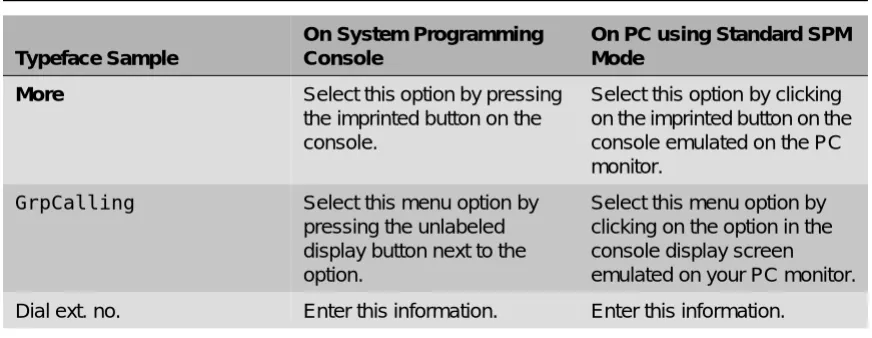
The arrows within the programming procedure separate each step. Three typefaces are used to help indicate what the step involves, as shown in the following table:
When programming from your PC with WinSPM in Standard SPM Mode, you can also select options from the console display screen by using the function keys on your keyboard. See ‘‘Using Standard SPM Mode’’ on page 3-27.
Table 1-1. Typefaces Used in Programming Procedures
Typeface Sample
On System Programming Console
On PC using Standard SPM Mode
More Select this option by pressing
the imprinted button on the console.
Select this option by clicking on the imprinted button on the console emulated on the PC monitor.
GrpCalling Select this menu option by
pressing the unlabeled display button next to the option.
Select this menu option by clicking on the option in the console display screen emulated on your PC monitor.
Moving Among System Programming Screens
Moving Among System Programming
Screens
1Some general comments regarding moving from one system programming screen to another follow:
■ In most cases, you can select Back to exit from a screen without making any changes. Exceptions to this are noted as part of a procedure. When you complete a procedure and select Back, you usually move up one screen in the menu hierarchy.
Occasionally, when you select Back, you return to the previous screen. In a few cases, pressing Back brings you back to the System Programming menu, where you can select another option to program or exit from system programming.
■ To complete a procedure and save the information you have programmed, select Enter.
■ If you are programming a group of sequentially numbered extensions or trunks, you may optionally select Next. This saves your entry and automatically provides the number of the next extension or trunk in the sequence, thus saving you several steps. If Next displays on the screen, you can use it with the current option.
■ In most cases, you will be at an intermediate step in the procedure you have just completed. At that point, you can select one of the options shown on the screen and continue programming, or you can select Back again. This usually takes you back to the System Programming menu. If not, you can continue programming on the current screen or select Back again.
About Programming and Idle States
1Some programming procedures can be started only when the entire system or some part of it, such as a trunk or an extension, is idle (not in use). Some procedures require that the trunk or extension be idle only at the instant of programming. Other procedures, which take longer, require the system, trunk, or extension to be forced to remain idle until programming is completed. These procedures wait for the system, trunk, or extension to become idle and then prevent the initiation of any new calls. This condition is called forced idle.
About System Programming
About Programming and Idle States If a procedure requires that the system be in an idle state and the system is busy when you begin, the screen shown below appears.
The screen changes to the appropriate programming screen when the system is no longer busy.
System Forced Idle
1When the entire system is forced idle, no calls can be made or received. The procedures listed below can be performed only when the entire system (every line and every extension) is idle:
■ Select system mode
■ Identify system operator positions
■ Renumber boards
■ Renumber system
■ Restore system programming information
■ Identify the Music-On-Hold jack
■ Program T/R on an 016 ETR module
When the system is forced idle, the following occurs: multiline telephone users hear a reminder tone that indicates the telephone cannot be used; display telephone users see the message
Wait: System Busy; single-line telephone users do not hear a dial tone.
Line or Trunk Idle
1Since these procedures require the line or trunk to be idle only at the instant of programming, the line or trunk is not forced idle. The following procedures can be performed only when the line or trunk being programmed is idle:
■ Identify loudspeaker paging line jack
■ Assign trunks to pools
■ Specify incoming or outgoing DID- or tie-trunk type
■ Specify tie-trunk direction
■ Specify tie-trunk E&M signal
System Busy Pls Wait
Dial Code nnnn
Slot/Port ss/pp
About Programming and Idle States
Extension Forced Idle
1When an extension is forced idle, no calls can be made or received on that extension. The following procedures can be performed only when the extension being programmed is idle:
■ Assign call restrictions
■ Assign pool dial-out restrictions
■ Copy extension assignments
■ Assign lines, trunks, or pools to extensions
■ Assign labels to a personal directory
■ Use centralized telephone programming
When the extension is forced idle, the following occurs: multiline telephone users hear a reminder tone that indicates the telephone cannot be used; display telephone users see the message
Wait: System Busy; single-line telephone users do not hear a dial tone.
Forced Idle Reminder Tone
1The forced idle reminder tone is a high-low “door-telephone” tone → 400 ms of 667 Hz tone followed by 400 ms of 571 Hz tone. The tone is provided under the following circumstances:
■ At the extension, to remind the user that the system or the extension is in the forced idle state.
■ At the programming console or at a PC running WinSPM, to remind the System Manager that the system (or at least one extension) is in the forced idle state because of administrative activity.
Forced idle reminder tones occur every 20 seconds. You can adjust the volume of these tones with the volume control on the system console or PC.
100D, 100DCD, or 100R INA Module Idle
1The following procedures can be performed only when the 100D, 100DCD, or 100R INA module is idle:
■ Specify board type
■ Specify frame format
■ Specify board signaling format
■ Specify board suppression format
Contents
2
System Programming Console
Overview . . . .
2-1
4424LD+ and MLX-20L Console Components . . . .
2-4
Direct Station Selector (DSS). . . .
2-5
System Programming Console Buttons . . . .
2-7
■
Fixed Display Buttons . . . .
2-8
■
Unlabeled Display Buttons . . . .
2-9
Console Overlay. . . .
2-9
Console and DSS Lights . . . .
2-11
■
Console Lights . . . .
2-11
■
DSS Lights . . . .
2-12
Displaying the System Programming Menu from the Console. . . .
2-12
Overview
2
System Programming Console
2Overview
2Overview
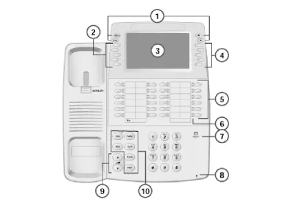
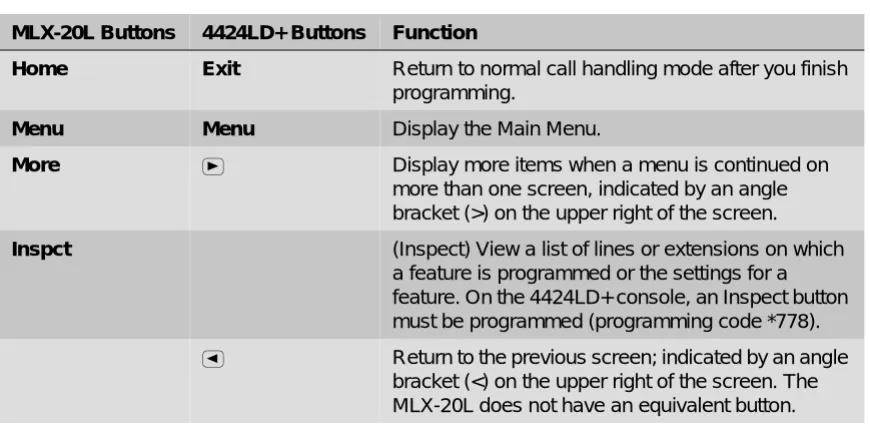
Figure 2-1. The 4424-LD+ Telephone
1 Fixed Buttons
2 Softkeys
3 7 Line x 24 Character Display
4 Softkeys
5 Line Buttons
6 LEDs
7 Message Waiting LED
8 Microphone
9 Volume
System Programming Console
Overview
Figure 2-2. The MLX-20L Telephone
1 Handset
2 Display Buttons
3 Call and Fixed-Feature Buttons
4 Display Screen
5 Direct Station Selector (DSS)
6 Volume Control
7 Fixed-Feature Buttons (8)
8 Dial Pad
9 Message Light
4424LD+ and MLX-20L Console Components
4424LD+ and MLX-20L Console Components
2Refer to the Figure 2-1 on page 2-2 and Figure 2-2 on page 2-3 for the location of the components described in this table.
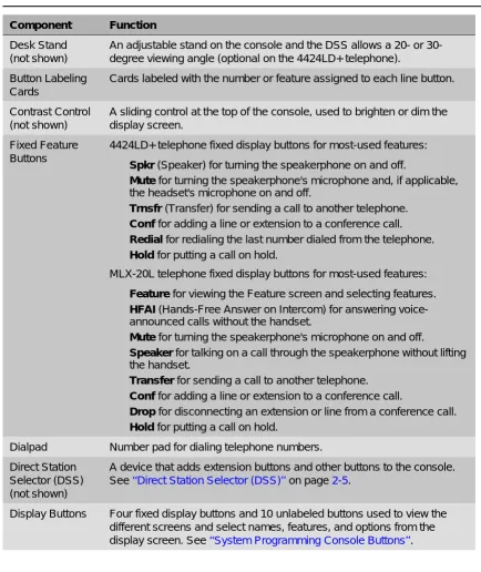
Table 2-1. 4424LD+ and MLX-20L Console Components
Component Function
Desk Stand (not shown)
An adjustable stand on the console and the DSS allows a 20- or 30-degree viewing angle (optional on the 4424LD+ telephone).
Button Labeling Cards
Cards labeled with the number or feature assigned to each line button.
Contrast Control (not shown)
A sliding control at the top of the console, used to brighten or dim the display screen.
Fixed Feature Buttons
4424LD+ telephone fixed display buttons for most-used features:
■ Spkr (Speaker) for turning the speakerphone on and off.
■ Mute for turning the speakerphone's microphone and, if applicable,
the headset's microphone on and off.
■ Trnsfr (Transfer) for sending a call to another telephone.
■ Conf for adding a line or extension to a conference call.
■ Redial for redialing the last number dialed from the telephone.
■ Hold for putting a call on hold.
MLX-20L telephone fixed display buttons for most-used features:
■ Feature for viewing the Feature screen and selecting features.
■ HFAI (Hands-Free Answer on Intercom) for answering
voice-announced calls without the handset.
■ Mute for turning the speakerphone's microphone on and off.
■ Speaker for talking on a call through the speakerphone without lifting
the handset.
■ Transfer for sending a call to another telephone.
■ Conf for adding a line or extension to a conference call.
■ Drop for disconnecting an extension or line from a conference call. ■ Hold for putting a call on hold.
Dialpad Number pad for dialing telephone numbers.
Direct Station Selector (DSS) (not shown)
A device that adds extension buttons and other buttons to the console. See ‘‘Direct Station Selector (DSS)’’ on page 2-5.
System Programming Console
Direct Station Selector (DSS)
Direct Station Selector (DSS)
2You can also have one or two Direct Station Selectors (DSSs) connected to the system programming console. Each DSS adds 50 extension buttons to the console, which facilitates assigning features to extensions. The DSS for the 4424LD+ console is the DSS 4450 shown in Figure2-3.
The LEDs on the DSS indicate the status of telephone features during system programming, such as calling restrictions. Each LED on the DSS represents an extension connected to the system. When certain features are selected from the System Programming menu, the LEDs on the DSS indicate the status of the feature for each extension. For example, if Restriction is selected from the Extension menu, the red LED is on for each extension that is toll-restricted.
The LEDs on a DSS change during programming:
■ If a local extension is busy because features are being assigned through system or centralized
telephone programming, the red LED next to the associated DSS button is on to indicate the busy condition. This occurs when the telephone with the attached DSS is not the one being programmed.
■ When you are using a telephone with an attached DSS to program itself or another extension,
all but the bottom two rows of LEDs on the DSS turn off during programming mode. The bottom two rows remain unchanged.
Display Screen Screen with a 7-line by 24-character display area that shows call information, features, prompts, date, and time.
Handset The hand-held part of the console you pick up, talk into, and listen from.
LEDs (Light-Emitting Diodes) The lights on the console that assist in checking feature status.
Line Buttons Buttons to make and receive calls; unlabeled buttons are programmable for one-step feature use. The 4424LD+ has 24 line buttons, and the MLX-20L has 20 line buttons.
Message Light A red light that signals a waiting message.
User Cards and Tray (MLX-20 only)
A slide-out drawer with erasable cards for noting telephone numbers and feature codes.
Volume Control A button for adjusting the volume of speaker, handset, headset, and ringer.
Table 2-1. 4424LD+ and MLX-20L Console Components—Continued
Direct Station Selector (DSS)
When you program a telephone with an attached DSS from another extension, all the LEDs on the DSS turn off, including the bottom two rows, during programming mode.
Figure 2-3. DSS4450 for 4400-Series Telephones
1 LEDs (50)
2 DSS Buttons (50)
3 Page Buttons
4 Message Status Button
System Programming Console
System Programming Console Buttons Refer to the Figure2-3 for the location of the components described in the following table.
System Programming Console Buttons
2Use the 14 buttons located on either side of the 4424LD+ or MLX-20L console display area for system programming. These buttons are arranged in two columns of seven buttons. On the 4424LD+ console, three of the four fixed display buttons have different labels than those on the MLX-20L console, although the same functionality is provided.
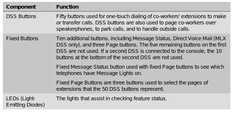
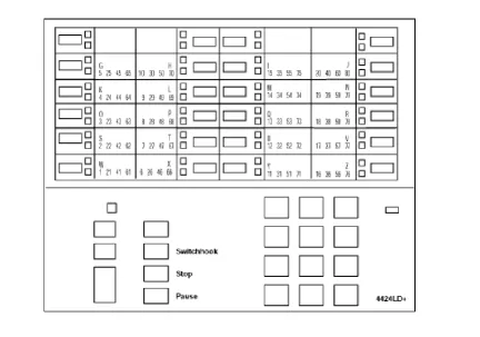
Figure 2-4. 4424LD+ Display Buttons and Main Menu Table 2-2. DSS 4450 Components
Component Function
DSS Buttons Fifty buttons used for one-touch dialing of co-workers' extensions to make or transfer calls. DSS buttons are also used to page co-workers over speakerphones, to park calls, and to handle outside calls.
Fixed Buttons Ten additional buttons, including Message Status, Direct Voice Mail (MLX DSS only), and three Page buttons. The five remaining buttons on the first DSS are not used. If a second DSS is connected to the console, the 10 buttons at the bottom of the second DSS are not used.
Fixed Message Status button used with fixed Page buttons to see which telephones have Message Lights on.
Fixed Page Buttons are three buttons used to select the pages of extensions that the 50 DSS buttons represent.
LEDs (Light-Emitting Diodes)
System Programming Console Buttons
Figure 2-5. MLX-20L Display Buttons and Main Menu
Fixed Display Buttons
2The top two buttons in each column have the same labels and functions regardless of the screen display. This type of button is called a fixed display button. The functions of the fixed display buttons for the 4424LD+ and MLX-20L consoles are described in the following table.
Table 2-3. Fixed Display Buttons Functions
MLX-20L Buttons 4424LD+ Buttons Function
Home Exit Return to normal call handling mode after you finish programming.
Menu Menu Display the Main Menu.
More Display more items when a menu is continued on
more than one screen, indicated by an angle bracket (>) on the upper right of the screen.
Inspct (Inspect) View a list of lines or extensions on which a feature is programmed or the settings for a feature. On the 4424LD+ console, an Inspect button must be programmed (programming code *778).
System Programming Console
Console Overlay
Unlabeled Display Buttons
2Use the five unlabeled display buttons on each side of the display screen to select commands, options, or items on the screen. The functions of these buttons vary, based on the option you select.
If you are using WinSPM in Standard SPM Mode for system programming, the simulated 4424DL+ or MLX-20L console screen on your PC monitor shows the PC function keys that correspond to the console screen selections. You can use the PC functions keys on your keyboard to select an item on the screen, or you can use your Mouse to select a function key or option in the simulated console screen.
Console Overlay
2The programmable line buttons are on the main part of the console. There are 24 line buttons on the 4424LD+; however, the four buttons on the top row are not used during system programming.
The MLX-20 console has 20 line buttons, but you can use the console overlay to program up to 28 line buttons on any extension through centralized telephone programming. Select Page 1 to access line buttons 1 through 20 and Page 2 to access line buttons 21 to 34. The top line of numbers next to each line button on the console overlay represents line buttons.
Console Overlay
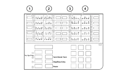
Figure 2-6. 4424LD+ System Programming Console Overlay
The function labeled Top Sys Prog on the MLX-20L console overlay does not appear on the 4424LD+ console overlay. The 4424LD+ does not provide a fixed HFAI (Hands Free Answer on Intercom) button for this feature; however, the HFAI feature can be
System Programming Console
Console and DSS Lights
Figure 2-7. MLX-20L System Programming Console Overlay
Console and DSS Lights
2The red and green lights (LEDs) next to each of the 20 line buttons on the 4424LD+ and MLX-20L console show the status of the line/trunk options. LEDs on the DSS show the status of features programmed on extensions.
Console Lights
2The green and red LEDs next to each button on the console display the status of the line/trunk option that is being programmed. For example, when you select Pools from the Lines Trunks menu, the red LED is off if the selected line is not in a pool and on if the line is in a pool. Appendix C in Feature Reference provides a table that shows the default LED status for line/trunk options.
1 To Central Office or Serving Facility
2 C O LInes
3 C O Line Protector
Displaying the System Programming Menu from the Console
DSS Lights
2The lights on the DSS (if one is attached to the console) show the status of features being programmed on the extensions. When you select a feature from a menu, the red LED next to the DSS button is on, off, or flashing, depending on whether the feature is already programmed on the corresponding extension. For example, when you select Toll Restrict from the Restrictions menu, the red LED next to the DSS button lights for each toll-restricted extension. Appendix C in Feature Reference, provides a table that shows the default DSS status of LEDs for system features.
Displaying the System Programming Menu
from the Console
2Follow these steps to begin system programming:
Menu
→
SysProgram→
StartThe System Programming Menu appears:
System Programming > System Programming:
Make a selection Make a selection
System Extensions Labeling Language
SysRenumber Options Data
Operator Tables Print
LinesTrunks AuxEquip Cntr-Prg
Back NightService Back
Table 2-4. Description of Options in System Programming Menu
Option Description
System Set system operating conditions.
SysRenumber Select the system numbering plan and/or
reassign extension numbers with 1- to 4-digit numbers that are more appropriate or convenient for your company.
Operator Assign or remove operator positions, and
program operator features (such as Operator Hold Timer or QCC options).
LinesTrunks Program line/trunk options.
Extensions Program extension features (such as line
assignments).
Options Program system-wide features (such as
System Programming Console
Exiting System Programming
Exiting System Programming
2Use the information in this table to return to the System Programming menu, the Main menu (Menu Mode screen), or the Home screen from within a programming screen.
Tables Program features that require entering
information in a table (such as Allowed Lists and Disallowed Lists).
AuxEquip Program auxiliary equipment connected to the
system (such as loudspeaker paging and fax).
NightSrvce Program Night Service features.
Labeling Program the labels shown on display
telephones (such as Posted Messages and entries in the System Directory).
Data Specify extensions that need voice and data
capability.
Print Print system programming reports (such as
system configuration and extension assignments).
Cntr-Prog Perform centralized telephone programming
(assign features to specific buttons on telephones).
Language Select the language for: the system,
4400-Series or MLX display telephones, SMDR reports, and print reports.
Table 2-5. Selections to Return to the System Programming Menu
To return to... Select...
Previous menu Back
Main menu Menu
Normal Call-Handling MLX-20L Console: Home 4424LD+ Console: Exit
Table 2-4. Description of Options in System Programming Menu—Continued
Contents
3
About WinSPM
Overview . . . .
3-1
System Requirements . . . .
3-2
Installing the WinSPM Software. . . .
3-3
Setting Up your Desktop . . .
3-5
■
Setting Font Size. . . .
3-5
■
Setting the Modem Definition . . . .
3-5
■
Setting the Start Bar “Auto Hide” Property/Changing
the Screen Resolution
. . . 3-7
Defining Your Password. . . .
3-8
Setting Up a Site . . .
3-9
■
Direct Connection . . . .
3-9
■
Internal Connection. . . .
3-11
■
External Connection . . . .
3-12
■
Manual Connection . . . .
3-13
■
Connecting a PC to a MERLIN MAGIX Integrated System . . . .
3-14
■
Direct Local Connection . . . .
3-14
■
About Surrogate Mode Programming . . . .
3-15
■
Internal Connection. . . .
3-16
■
External Connection . . . .
3-16
About the WinSPM Main Screen Options . . . .
3-17
Using View . . . .
3-18
Using Tools . . . .
3-18
Using Quick Access . . .
3-19
■
Allowed/Disallowed Lists. . . .
3-19
■
Automatic Route Selection (ARS). . . .
3-20
■
Call Pickup Groups . . . .
3-20
■
Calling Group . . . .
3-20
■
Capture Data. . . .
3-22
■
Coverage Groups . . . .
3-23
■
Labeling . . . .
3-23
■
Personal Lines . . . .
3-23
■
Set Date and Time . . . .
3-24
■
Speed Dial . . . .
3-24
■
Station Responding Test. . . .
3-25
■
System Inventory . . . .
3-25
■
Telephone Restrictions . . . .
3-26
WinSPM Help. . . .
3-27
Using Standard SPM Mode . . . .
3-27
■
Displaying the SPM Main Menu . . . .
3-27
■
About the Emulation Window . . . .
3-28
■
Options in the SPM Main Menu . . . .
3-30
Basic System Management Procedures . . . .
3-31
■
Backup . . . .
3-31
■
Boards . . . .
3-33
■
Browse . . . .
3-36
■
Language . . . .
3-38
■
Maintenance . . . .
3-39
■
Pass-Thru . . . .
3-39
■
Password . . . .
3-41
■
Print Options . . . .
3-43
■
Restore . . . .
3-44
■
System Programming . . . .
3-46
Board Renumbering with the
016 MLX Module . . . .
3-46
■
Adding a 016 Module at the End of an Existing
System
. . . 3-47
■
Replacing Two 008 MLX Modules with One 016 MLX Module When
the 008 MLX Modules are the Last Two Modules in the System
. . . 3-48
■
Replacing a 008 MLX Module with a 016 MLX Module . . . .
3-49
■
Replacing a 008 OPT Module with a 016 MLX Module . . . .
3-51
Overview
3
About WinSPM
3Overview
3The Windows System Programming and Maintenance (WinSPM) software package offers an alternate method of programming the MERLIN MAGIX Integrated System using a PC. This method frees the system programming console for other uses and also provides the following additional functions:
■ Backing up system programming information.
■ Restoring system programming information from a backup.
■ Printing, viewing, and storing reports.
■ Programming the system remotely.
■ Programming in surrogate mode.
■ Creating button labels.
■ Storing print report data and/or user annotation notes using Notepad Editor.
WinSPM provides two modes for programming your MERLIN MAGIX Integrated System:
■ Quick Access Mode. A graphical interface (GUI) for those tasks most commonly performed
by the System Manager–for example, adding or deleting members of groups, performing system inventories, creating reports, administering multiple systems, making station labels shown on display telephones, and more.
■ Standard SPM Mode. Provides an emulation display of the system programming console. It
allows basic SPM programming of the MERLIN MAGIX system and supports SPM programming for options not included in Quick Access mode.
WinSPM is available on CD-ROM. The WinSPM software can be used directly from the CD-ROM on your PC. If your PC has a hard disk, however, you should install WinSPM from the CD-ROM onto the hard disk.
System Requirements
System Requirements
3WinSPM is designed to function with:
■ Windows 95, Windows 98, Windows Me, or Windows NT Release 4.0 or higher
■ IBM-compatible Personal Computer with a Pentium 100 or more (Pentium II or higher recommended)
■ 40 MB or more of available space on the hard drive
■ 32 MB of RAM (64 MB recommended)
■ 1 COM Port
■ Modem with auto baud capabilities (PEC 2569-839 recommended), with specific drivers loaded
■ Video Card that supports at least 256 colors (65536 or more recommended)
Depending on how you connect the PC to the control unit, you also need the following items:
■ Direct local connection, if the PC is within 50 feet of the control unit:
— Either a 355AF modular adapter (if there is a male connector on the interface cable) or a 355A modular adapter (if there is a female connector on the interface cable)
— A four-pair modular cord (D8W)
■ Direct local connection, if the PC is more than 50 feet from the control unit:
— 355AF adapter — EIA crossover cable
— Two Z3A2 Asynchronous Data Units (ADUs) — ADU crossover cable
— 400B2 power adapter — 2012D transformer
— BR1A-4P adapter and either a 102 connecting block or 103 connecting block — 248B adapter
— Eight-position wall jacks — Four-pair plug-ended cable — D8W cords
— D6AP power cord — EIA-232-D cables
About WinSPM
Installing the WinSPM Software
■ Internal or External connection:
— Modem that supports 1200- or 2400-bps connections — Modem cable
In addition, a parallel printer is useful for reports. The PC needs a parallel port for the connection.
Installing the WinSPM Software
3The WinSPM software is installed from the CD-ROM.
1. Insert the CD-ROM into your CD-ROM drive.
2. From the Start menu, select Run.
3. When prompted for the file or folder you want to open, type D:\setup.exe. (If your CD-ROM drive is set up as a different drive letter, replace D as necessary.)
Installation creates a program group named “Lucent Solutions.” This group contains a folder titled “WinSPM,” which contains an icon titled “WinSPM.” Clicking on this icon starts the WinSPM application. Upon installation of the WinSPM software, the WinSPM main screen appears (see
‘‘About the WinSPM Main Screen Options’’ on page 17 for more information):
Installing the WinSPM Software
Figure 3-1. WinSPM Main Screen
After WinSPM is installed, the First Time User Wizard (FTUW) assists you through the following four steps described in detail on the following pages:
■ Setting Up Your Desktop
■ Defining Your Password
■ Setting Up a Site
About WinSPM
Setting Up your Desktop
Setting Up your Desktop
3Setting up your desktop includes the following tasks:
■ Setting Font Size
■ Setting the Modem Definition
■ Setting the Start Bar Auto Hide Property/Changing the Screen Resolution
Setting Font Size
3At present, WinSPM does not support large fonts. Some fonts may be virtually unusable if Large Fonts is selected on the settings tab of the Display Properties window. To correct this setting:
1. Anywhere on your desktop, right-click and select Properties on the pop-up menu. The Display Properties window appears.
2. Click the Settings tab.
3. In the Font Size field, select Small Fonts from the drop-down list box.
4. Click Apply.
5. To close the window, click OK.
Setting the Modem Definition
3If you are using a modem to connect to a MERLIN MAGIX Integrated System, and you have set the Maximum Speed to above 2400 baud, the modem in the MERLIN MAGIX Integrated System may time-out before your modem has enough time to step down to 2400 baud and establish communications. For this reason, it is suggested that you use a modem definition with a Maximum Speed of 2400 baud. You can create a new modem definition while retaining your original, higher speed definition if you choose.
Modifying an Existing Modem Definition
3If your system is dedicated for connection with WinSPM to the MERLIN MAGIX Integrated System for programming and the modem on that system will not be used for any other purpose, do the following:
1. From the desktop, click Start.
2. Go to Settings and choose Control Panel.
3. Double-click the Modems icon. A list of modems configured in the system is displayed.
4. Highlight the name of the modem that is used to connect to the MERLIN MAGIX Integrated System and click the Properties button.
5. On the General tab, change the value in the drop-down list under Maximum Speed to 2400.
Setting Up your Desktop
Connection Preferences
Data Bits: 8
Parity: None
Stop Bits: 1
[X] Wait for dial tone before dialing
Advanced
[X] Use Flow Control
[X] Hardware (RTS/CTS)
7. To save the new settings, click OK.
8. To close the Modem Properties dialog box, click Close.
9. From the Control Panel, click File, then choose Exit to close the Control Panel and return to the Windows desktop.
Adding a New Modem Definition
3If the system you are using is not dedicated for connection with WinSPM to the MERLIN MAGIX Integrated System for programming and the modem on that system can be used for other purposes, do the following:
1. From the Windows desktop, click Start.
2. Go to Settings and choose Control Panel.
3. Double-click the Modem icon. A list of modems configured in the system is displayed.
4. Take note of the name of the modem that is currently being used in the system to make connection to the MERLIN MAGIX Integrated System.
5. Press the Add button. The Install New Modem Wizard appears.
6. Select the “Don’t detect my modem” check box and click Next.
7. Highlight the name of the modem manufacturer for your modem.
8. Highlight the name of your modem in the Models list and click Next.
9. Select the COM port that corresponds to the COM port used by your modem and click Next.
10. Once your modem is set up successfully, click Finish to complete the operation. The new modem now appears in the list of modems on the Modem Properties form (usually with the same name as the modem identified in Step 4) with a #2 after it.
11. Highlight the name of the new modem and click Properties.
About WinSPM
Setting Up your Desktop 13. Verify the following settings:
Connection Preferences
Data Bits: 8
Parity: None
Stop Bits: 1
[X] Wait for dial tone before dialing.
Advanced
[X] Use Flow Control
[X] Hardware (RTS/CTS)
14. To save the new settings, click OK.
15. To close the Modem Properties dialog box, click Close.
16. From the Control Panel, click File, then choose Exit to leave the Control Panel and return to the Windows desktop.
Setting the Start Bar “Auto Hide” Property/Changing
the Screen Resolution
3Some WinSPM screens may be difficult to use in 640x480 resolution because they use the full height of the screen. For this reason, you must either turn “Auto hide” on for the Taskbar or increase your screen resolution settings. If you cannot see the OK button at the bottom of the screen, perform one of the following procedures.
Setting the Start Bar “Auto hide” Property
31. Right click an area of the Taskbar that is not a button. By default, the Taskbar is located at the bottom of the screen.
2. Select “Properties” from the pop-up menu.
3. On the Taskbar Properties dialog box, make sure that the “Auto hide” check box is selected.
4. Click Apply, then click OK. The Taskbar disappears. To bring up the Taskbar, simply move your mouse to the edge of the screen where it was previously displayed.
5. You should now be able to see the OK button. Simply click it to continue your first-time execution of WinSPM.
Defining Your Password
Changing the Screen Resolution
31. On the Taskbar, click Start.
2. Select Settings, then Control Panel.
3. Click the Display icon.
4. When the “Display Properties” dialog box appears, click the Settings tab.
5. Move the Desktop Area slider so that the resolution setting is higher than 640 x 480.
6. Click Apply.
7. You should now be able to see the OK button. Simply click it to continue your first-time execution of WinSPM.
Defining Your Password
3There are two passwords in WinSPM:
■ Application Password. There is an application-level password that serves as a security
measure for accessing the WinSPM software itself. You are prompted to enter this password during the application login. Any characters that can be entered with the keyboard are acceptable. An asterisk displays for each password character entered. Since the actual password characters are not displayed, you are prompted to reenter your password for confirmation.
■ System Password. A password is always required to establish a modem connection with the
MERLIN MAGIX Integrated System. You can perform remote system programming only if you enter the correct password. (See ‘‘Password’’ on page 3-41 for details on establishing your system password.)
SECURITY ALERT:
■ The password characters do not appear on the screen as you type them.
■ Use a minimum of five characters.
About WinSPM
Setting Up a Site
Setting Up a Site
3To use the WinSPM software, your PC must be connected to the MERLIN MAGIX Integrated System directly via a serial port on your PC; otherwise you must connect to the MERLIN MAGIX system’s internal modem using your PC’s modem.
Once you install WinSPM on your PC, the First-Time User Wizard guides you through setting up your application password and using the Site Setup option to create “sites” that correspond to the MERLIN MAGIX Integrated System that you are responsible for programming. Each site can be labeled with as much information as you need to differentiate one site from another.
When you set up a site, you must first determine how your PC will connect to the MERLIN MAGIX Integrated System you want to program. A site can have multiple connection types set up. There are four connection types available (setup instructions for each type are provided on the following pages):
■ Direct Connection. A serial port on your PC is connected directly to the MERLIN MAGIX
system programming jack—the lower modular RS-232 jack on the processor module.
■ Internal Connection. You are using a modem (either connected to or built into your PC) that is
connected to the MERLIN MAGIX Integrated System (for example, via a 016 T/R module) to access the MERLIN MAGIX internal modem.
■ External Connection. You are using a modem (either connected to or built into your PC) and
using a dial-up connection to access the MERLIN MAGIX internal modem. The External Connection type requires use of the Remote Access feature to allow you to connect to the MERLIN MAGIX programming port without manual intervention.
■ Manual Connection. You are using a modem (either connected to or built into your PC) and
using a dial-up connection to access the MERLIN MAGIX internal modem. The Manual Connection is used when you must reach the MERLIN MAGIX programming port by placing a call to the site and the person who answers transfers your call to the programming port.
Direct Connection
3To set up a site for a Direct Connection, follow these steps:
1. From the Site Setup screen, click Add. The cursor moves to the Site Name field.
Setting Up a Site
3. Complete the following fields to help differentiate this site from any other site(s) you may want to add. These fields are not required; therefore, you may fill in as many or as few as you determine necessary:
— Address — City — State — Postal Code — Country — Contact — Telephone — Notes
4. Click the Direct Connection tab.
5. Select t