ISSN: 2395-3519
www.ijatca.com 24
International Journal of Advanced Trends in
Computer Applications
www.ijatca.com
TRM ARRAY ANTENNA FAILURE COMPENSATION
USING GA and ACO
1
Navdeep Singh
1
M.tech Student
Rayat and Bahra Group of Colleges
2
Er. Vivek Gupta
1
Assistant Professor, Rayat and Bahra Group of Colleges
Abstract: TRM array antenna is used in wireless communication system. There are various problem which may occur while the transmission of the data. The biggest problem is of routing. This paper focuses on the optimized routing using ACO which would be compared with the routing of GA. This paper presents a hybrid algorithm for the reduction of SLL and energy.
Keywords:TRM ARRAY ANTENA, GA, ACO.
I.
INTRODUCTION
For wireless communication system, the antenna array is one of the most important components to improve the system capacity and spectral efficiency. The active antenna array is widely used in many applications like satellite communication, sonar, mobile communication etc. for signal acquisition purpose [1]. Generally the antenna array consists of large number of radiating elements or sub- arrays. Generally the antenna array consists of large number of radiating elements or sub- arrays. Due to large number of elements presented in an array, there is always a possibility of failure of one or more elements in the antenna array system. The failures of elements in the array destroy the symmetry and may cause sharp variation in intensity across the array, distort the pattern in the form of increased side lobe level.
The degradation of the capacity of
transmitter/receiver module (TRM) distorts the beam pattern; that is, the side lobe level (SLL)
increases [2]. Array processing involves
manipulation of signals induced on various antenna elements. Its capabilities of steering nulls to reduce
co channel interferences and pointing independent beams toward various mobiles, as well as its ability to provide estimates of directions of radiating sources, make it attractive to a mobile communications system designer. Array processing is expected to play an important role in fulfilling the increased demands of various mobile communications services [3].
Antenna Array is formed by assembly of radiating elements in an electrical or geometrical configuration. In most cases the elements are identical. Total field of the antenna array is found by vector addition of the fields radiated by each individual element. There are five controls in an antenna array that can be used to shape the pattern properly, they are, the geometrical configuration (linear, circular, rectangular, spherical etc.) of the overall array, relative displacement between elements, excitation amplitude of the individual elements, excitation phase of the individual elements and relative pattern of the individual elements. In many communication applications it is required to design a highly directional antenna.
ISSN: 2395-3519
www.ijatca.com 25
linear array has all its elements placed along a straight line, with a uniform relative spacing between elements. The goal in antenna array geometry synthesis is to determine the physical layout of the array that produces the radiation pattern that is closest to the desired pattern [4-6]. Today a lot of research on antenna array is being carried out using various optimization techniques to improve null performance due to their robustness and easy adaptively. One among them is Genetic Algorithm, a method for null control and their effects on the radiation pattern [7] [8].
A genetic algorithm (GA) is a method for solving both constrained and unconstrained optimization problems based on a natural selection process that mimics biological evolution. The algorithm repeatedly modifies a population of individual solutions. At each step, the genetic algorithm randomly selects individuals from the current population and uses them as parents to produce the children for the next generation. Over successive generations, the population "evolves" toward an optimal solution. Multiple antenna structures can be divided into three groups: use of antenna array only at receiver, known as single-input multiple-outputs (SIMO) systems; use of antenna array only at transmitter, known as multiple-inputs single-output (MISO) systems; and use of antenna arrays at both transmitter and receiver, known as inputs multiple-outputs (MIMO) systems.
GA is one of the most advance techniques which is getting used world wide web for each and every purpose. In the same manner GA has been used for the optimization of the TRM antenna failure also. In this work the hybridization of the Genetic and Ant Colony Optimization takes place to decrease the side lobe levels.
II.
ARRAY ANTENNA TRM
FAILURE COMPENSATION
During the operation of an array antenna system, TRM failure can occur at any time. When a TRM failure occurs, the TRM is supposed to be turned off. When recalculation is done with the remaining TRMs, a resynthesized beam pattern is constructed within a beam pattern mask. Then, the newly calculated amplitude and phase distributions are
reset. In TRM Antenna Transmission using MIMO system reduces bit error rate has been challenge from decade. In addition to this, if any receiving antennas get damaged, it is difficulty from a routing table to generate a routing set which is feasible without damaged antenna. Our basic problem is to generate a routing table by using GA.
To solve the problem a virtual node concept which would be activated if any of the receiving antenna is highly heated up. This virtual node will receive signal instead of that heated antenna until and unless the heated antenna get cooled. We start with static routing. If congestion occurs, we call for GA .If the node selected by the GA consumes less energy than the conventional path, then we add the path to the routing environment, else we choose for next path as shown in Fig.1
Fig1.Flowchart explaining the GA used in the proposed algorithm.
III.
ANT COLONY SWARM
OPTIMIZATION
ISSN: 2395-3519
www.ijatca.com 26
ANT COLONY by changing their positions and the fitness frequently, the flying direction and velocity are determined by the objective function.
ACO Algorithm
Assuming Xi=(xi1,xi2,…xiD) the position of i-th
ANT COLONY in D-dimension,
Vi=(vi1,vi2,….,viD) is its velocity which represents
its direction of searching. In iteration process, each ANT COLONY keeps the best position p best found by itself, besides, it also knows the best positioning best searched by the group ANT COLONYs, and changes its velocity according two best positions. The standard formula of ACO is as follows:
In which i=1,2,…N,
N-the population of the group ANT COLONYs; d=1,2,…D;
k-the maximum number of iteration; ,-the random values between [0,1], which are used to keep the diversity of the group ANT COLONYs;
c1,c2; the learning coefficients, also are called acceleration coefficients;
v1d k
-the number d component of the position of ANT COLONY in k-th iterating; pad, the number d component of the best position particles has ever found; pad, the number d component of the best position the group ANT COLONYs have ever found.
The procedure of standard ACO is as following:
1)Initialize the original position and velocity of ant swarm.
2)calculate the fitness value of each ANT COLONY;
3)For each ANT COLONY, compare the fitness
value with the fitness value of p best, if current value is better, then renew the position with current position, and update the fitness value simultaneously;
4) Determine the best ANT COLONY of group with the best fitness value, if the fitness value is better than the fitness value of g best, then update the g be stand its fitness value with the position;
5) Check the finalizing criterion, if it has been satisfied, quit the iteration; otherwise, return to step 2.
FITNESS FUNCITON OF ACO:
P_FIT= Min (sqrt(A(x)^2-B(x)^2));
Where B is the energy at next node and A is the energy of first block.
IV.
GENETIC AND ACO
ALGORITHM HYBRIDIZATION
In this section we intend to hybridize ACO and GA in such a manner that they complement each other for feature selection in protein function prediction. ACO and GA are used to explore the space of all subsets of given feature set. The performance of selected feature subsets is measured by invoking an evaluation function with the corresponding reduced feature space and measuring the specified classification result. The best feature subset found is then output as the recommended set of features to be used in the actual design of the classification system. The process begins by generating a number of ants and a population in GA.
ACO and GA generate feature subset in parallel and the resulting subsets are gathered and then evaluated at the end of iterations. The best subset is selected according to evaluation measures. If an optimal subset has been found or the algorithm has executed a certain number of runs, then the process halts and outputs the best feature subset encountered. If none of these conditions hold, then all ants can update the pheromone according to Eq. (4), the best ant deposits additional pheromone on nodes of the best solution.
ISSN: 2395-3519
www.ijatca.com 27
cross-over and mutation operations. This leads to the exploration of ants around the optimal solution in next iterations. After updating pheromone, the process iterates once more.
V.
PARAMETERS USED
A.SNR (SIGNAL TO NOISE RATIO)
Short for signal-to-noise ratio, the ratio of the amplitude of a desired analog or digital data signal to the amplitude of noise in a transmission channel at a specific point in time. SNR is typically expressed logarithmically in decibels (dB). SNR measures the quality of a transmission channel or an audio signal over a network channel. The greater the ratio, the easier it is to identify and subsequently isolate and eliminate the source of noise. A SNR of zero indicates that the desired signal is virtually indistinguishable from the unwanted noise.
B.BER (BIT ERROR RATE)
Short for bit error rate. In a digital transmission, BER is the percentage of bits with errors divided by the total number of bits that have been transmitted, received or processed over a given time period. The rate is typically expressed as 10 to the negative power. For example, four erroneous bits out of 100,000 bits transmitted would be expressed as 4 x 10⁻⁵, or the expression 3 x 10⁻⁶ would indicate that three bits were in error out of 1,000,000 transmitted. BER is the digital equivalent to signal-to-noise ratio in an analog system.
VI.
RESULTS AND DISCUSSION
Result Figure 1.1
The above figure represents the side lobe level of the Genetic Algorithm whose tabular description is already provided in the table.
The following figure represents the SLL representation using GA.
ISSN: 2395-3519
www.ijatca.com 28
The hybrid algorithm is a combination of ACO and Genetic whose graphical representation is as follows.
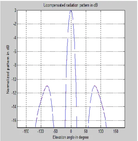
Result Figure 1.3
The above figure shows the uncompensated pattern in case of GA+ACO having high side lobe levels.
Result figure 1.4
The above figure shows the compensated pattern in case of GA+ACO having low side lobe levels.
CONCLUSION
The technology for design and development of a large phased array is presently available.
However, it has not reached the maturity and low cost levels needed to make it competitive with a reflector antenna system at the present time. It is to believe that in the next 10- 15 years the breakthroughs in mass production techniques at the components, modules and integrated circuit board level will be achieved that will make it an attractive option. There are many advantages to a phased array system as compared to the current 70m DSN antenna network. These include high beam agility, multi-beam multi target applications, high reliability and easy maintainability.
The disadvantages include much higher cost at
the present, complexity of multi-frequency
operations, inflexibility in adding new frequencies, and lower gain at lower elevations for a flat horizontal array. The technology risks and the cost drivers include, primarily, the T/R modules and the
beam-forming network architecture and
implementation. It is propose that, as a proof of concept demonstration, a small scalable flat panel array be built and tested, in order to prove the maturity of the concept and to work out the potential problems at the T/R module and the beam-forming levels, for achieving a GA-level performance. This could be aim-square array at WKa bands. This panel could become an element of a much bigger array composed of such modular elements. The architecture of the connectivity and integration of this panel into a larger system would also be part of the proposed work.GA performance is better.
SNO. UNCOMPENSATED COMPENSATED
WITH GA
-11.70 db -12.6 db
WITH GA+ACO
-11.70 db -15.50 db
Table 1. Comparison Table
ISSN: 2395-3519
www.ijatca.com 29
compensation to the antenna through GA.
If the side lobe will reduce, then the probability of error over the transmission also reduces. If the error rate reduces, then the energy consumption also reduces.
VII.
FUTURE SCOPE
There are several methods for reflect array elements to achieve the desired planar phase front. The first uses identical micro strip patches with different length phase delay lines attached so that they can compensate for the unequal phase delays due to the differing path lengths from the illuminating feed. Low-loss electronic phase
shiftless employing micro-electro-mechanical
switches (MEMS) can be inserted into these phase-delay lines to achieve electronic beam scanning. Since the antenna contains a very large number of elements, 2- or 3-bit phase shifters with low insertion loss are sufficient to achieve good overall beam scan resolution. The parallel-fed reflection-type phase shifters generally yield lower insertion loss than the conventional series-fed transmission-type phase shifters. The second method, which only works with circular polarization, employs identical circularly polarized elements with different angular rotations to compensate for the feed path length differences. Micro-machined motor can be placed underneath each patch to mechanically rotate the element and effect fast beam scanning. With this approach, there is nearly no insertion loss associated with the elements and beam- scanning speeds of the order of milliseconds can be readily achieved. Other than this there are several future generation algorithms which can be combined with GA to optimize the results like, Neural networks or fuzzy logics. The future researchers can try their hands on this scenario.
REFERENCES
[1]. Narwant S. Grewal, Munish rattan and Manjeet S. Patterh, “A linear antenna array failure correction Using firefly algorithm”, progress in electromagnetics research m, vol. 27, 241{254, 2012}.
[2]. Jung-Hoon Han, Sang-Ho Lim and Noh- Hoon Myung, “Array antenna trm failure compensation using Adaptively weighted beam pattern mask Based on
genetic algorithm,” ieee antennas and wireless propagation letters, vol. 11, 2012.
[3]. Lal c. Godara, “Application of antenna arrays to mobile Communications, part ii: beam-forming And direction-of-arrival considerations,” proceedings of the ieee, vol. 85, no. 8, august 1997.
[4]. C. A. Ballanis, "Antenna theory analysis and design," 2nd edition, john willey and son's inc .• new york, 1997.
[5] Elliott, R. S., "Antenna Theory and Design", revised edition, john wiley, new jersey, 2003.
[6]. R. L. Haupt, and d. H. Werner, "Genetic algorithms in electromagnetics", IEEE press wiley-interscience, 2007.
[7]. R. L. Haupt, "Optimized element spacing for low sidelobe concentric Ring arrays," IEEE trans. Antennas propag., vol. 56(1), pp. 266-268, Jan. 2008.
[8]. H. Steyskal, r. A. Shore, and r. L. Haupt, "methods for null control And their effects on the radiation pattern," IEEE trans. Antennaspropagat., vol. 34, no. 3, pp. 404-409, mar. 1986.
[9]. Mohammad Ali Khalighi, Kosai Raoof and Geneviève Jourdain, “capacity of wireless communication systems Employing antenna arrays, a tutorial study,” wireless personal communications 23: 321–352, 2002. © 2002 kluwer academic publishers. Printed in the netherlands.
[10]. Michael A. Jensen, “A Review of Antennas and Propagation for MIMO Wireless Communications,” IEEE transactions on antennas and propagation, vol. 52, no. 11, november 2004.
[11].Benjamin Bräutigam, Marco Schwerdt, and Markus Bachmann, “An Efficient Method for Performance Monitoring of Active Phased Array Antennas,” IEEE transactions on geoscience and remote sensing, vol. 47, no. 4, april 2009.
[12]. Bipul Goswami and Durbadal MandaI, “Introducing Deeper Nulls and Reduction of Side Lobe Levels in a Symmetric Linear Antenna Array Using Genetic Algorithm,” 1 st int'I Conf. on Recent Advances in Information Technology I RAIT-2012 I.
ISSN: 2395-3519
www.ijatca.com 30
[14]. Alka Verma, “Analysis And Design Of E Shaped Patch Antenna In X Band,” International Journal Of Advanced Engineering Technology E-Issn 0976-3945.
[15]. Tomohiko Mitani, Shunji Tanaka, Yoshio Ebihara, “An Efficient Algorithm for Transmitting Power Maximization of Phased Arrays Including Amplitude Degradation,” Proceedings of the "2013 International Symposium on Electromagnetic Theory.