Journal of Engineering Sciences, Volume 6, Issue 2 (2019), pp. E 31–E 35 E 31 JOURNAL OF ENGINEERING SCIENCES
ЖУРНАЛ ІНЖЕНЕРНИХ НАУК
ЖУРНАЛ ИНЖЕНЕРНЫХ НАУК
Web site: http://jes.sumdu.edu.ua DOI: 10.21272/jes.2019.6(2).e5 Volume 6, Issue 2 (2019)
Numerical Experiment for the Calculation of Normal Contact Stress
in the Deformation Center when Rolling a Metal Strip
Yavtushenko A. V.1*, Protsenko V. M.1, Bondarenko Y. V.1, Kirichenko A. G.1, Ping F. Y.2 1 Zaporizhzhia National University, 226 Soborny Ave., 69006 Zaporizhzhia, Ukraine;
2 Fujian Xiangxin Co. Ltd, Fuzhou, Fujian, China
Article info: Paper received:
The final version of the paper received: Paper accepted online:
September 4, 2019 December 1, 2019 December 6, 2019
*Corresponding Author’s Address:
[email protected]
Abstract. The possibility of application of the program complex called Mathcad Prime 5 for calculation of normal contact stresses in the center of deformation during cold rolling of the strips is considered. The algorithm, the block-scheme and the computer program of calculation of the normal contact stresses during rolling of the strips on the re-verse mill 1680 PJSC “Zaporizhstal” are developed. The epures were constructed and a comparative analysis of the formulas used to calculate the normal contact stresses in the deformation center was carried out. Received calculation data in Mathcad Prime 5 coincides with the literary data, which has practical value for both educational process and research and design work. Based on the analysis of the contact stress epures, it can be concluded that the most accu-rate calculation of the total metal pressure on the rolls during cold rolling is possible only when the formulas used ещ consider the change in the forced yield strength in the deformation center by the law of a straight line or the parabolic law.
Keywords: cold rolling strips, normal contact stress, deformation center, computer program, forced yield strength.
1
Introduction
The theory and practice of cold rolling have a long his-tory of development. With the efforts of many research-ers, theoretical and empirical dependencies between the basic parameters have been found that influence the pro-cess of cold rolling and are the basis for the design of the created cold rolling mills and mills that are being de-signed. These dependencies were not designed for the use of computer technology, so they are mostly presented in an explicit way and, in some cases, as nomograms.
The availability of ready-made formulas has its posi-tive aspects, but with the use of computer technology, more opportunities for research and calculation and theo-retical work appear. Sometimes the complexity of math-ematical expressions does not allow us to solve the equa-tions obtained. This can be avoided by having a comput-er-based numerical calculation program in place, that is, a numerical experiment method.
2
Literature Review
The aim of the study is the development of an algo-rithm and computer programs that calculate the normal contact stress in the deformation center during cold roll-ing of the strips on the reversed mill 1680 PJSC
“Za-porizhstal” with the help of the software complex Mathcad Prime 5. Another aim is the comparative analy-sis of the formulas, which are used to calculate the nor-mal stress in the deformation center.
The application of a modern computer program deter-mines the relevance and practical significance of this article for both the educational process and research and design work.
A considerable number of works [1–10] were devoted to the issue of calculating the normal contact stresses in the deformation center during the rolling of the strips.
The calculation of normal contact stresses during roll-ing of the thin strips can be performed usroll-ing the formulas of A. I. Tselikov [4–7]:
for the zone of slippage on the entry side
(
1)
0 1;0 0
+ − =
x
x
h h K
p (1)
for the zone of slippage on the delivery side
(
1)
1,1 1
1
− + =
h
h
p x
E 32 MECHANICAL ENGINEERING: Computational Mechanics where px – normal contact stress, MPa; h0 and h1 – initial
and final thickness of the strip, mm; hx – thickness of the strip in the arbitrary intersection of the deformation cen-ter, mm; ξ0 and ξ1 – coefficients of the back and front tension.
In these equations the constant coefficients are deter-mined by the formulas:
, 1 ; 1 ; 2 1 1 1 0 0 0 K K h д l f = − = − =
where σ0 and σ1 – front and back tension, MPa; K0 and
K1 – forced yield strengths before and after rolling in MPa (K0 = 1.15·σ0.2(0); K1 = 1.15·σ0.2(1)); σ0.2(0) and σ0.2(1) – conditional yield strengths before and after rolling, MPa; Δh – absolute compression, mm; ld – length of defor-mation center, mm; f – coefficient of friction.
The determination of the total metal pressure on the rolls by formulas (1), (2) is the most accurate, which has been confirmed by numerous experiments [4–7]. Howev-er, the use of these formulas, taking into account the law of the yield strength change in the deformation center depending on the compression, leads to cumbersome final formulas, which are inconvenient for practical calcula-tions.
Considering K = px, formulas (1), (2) are simplified to the form [7]:
– for the zone of slippage on the entry side:
; 1 0 0 0 − = x x h h K p (3)
– for the zone of slippage on the delivery side:
; 1 1 1 1 + = h h K p x x (4)
The obtained formulas are extremely simple, but they do not sufficiently take into account the change in yield strength during the deformation process.
For more accurate accounting for the change in the forced yield strength in the deformation canter from K0 to
K1, the following equations are obtained, assuming that the change in the yield strength occurs by the law of a straight line [7]:
– for the zone of slippage on the entry side:
(
)
(
)
(
1 0)
;1 0 0 0 1 0
0
− − − + − = − h h K K h h h h K K
p x x
x
K
(5)– for the zone of slippage on the delivery side:
(
)
(
)
(
)
; 0 1 1 1 1 0 1 11
− + − − − = + h h K K h h h h K K
px
K
x x (6)In fact, the change in yield strength in the process of deformation occurs by parabolic law. Taking this into account, the following equations are obtained [7]:
– for the zone of slippage on the entry side:
(
)
− − − + − + = 1 0 1 1 0 0 2 0 1 2 0 0 h x h h h h h K K K x p(
)
− + − − 1 1
2 0 1
2 hx hx h
h K K
(7)
– for the zone of slippage on the delivery side:
(
)
+ + − − − = 1 1 2 0 1 ) 1 ( 2 1 2 1 1 h x h h K K h K x p(
)
− − − + 1 1
2 0 1
2 hx hx h
h K K
(8)
In order to compare the results of the calculation of normal contact stresses for all four considered formulas (1)–(2), (3)–(4), (5)–(6), and (7)–(8) in accordance with the real modes of compression on the reverse mill of 1680 PJSC “Zaporizhstal”, an algorithm and a program for the calculation in Mathcad Prime 5 software complex [11] were developed.
3
Research Methodology
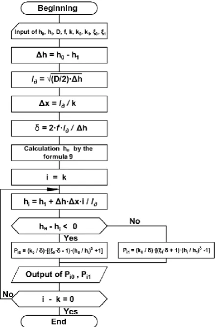
In order to determine the values of the pressure in an arbitrary intersection of the deformation center, a calcula-tion algorithm has been developed, which is shown in the block diagram of Figure1. The scheme relates to the cal-culation of formulas (1), (2); other formulas are calculat-ed using a similar scheme.
The deformation center is divided into a series of in-tersections (from 0 to k). In each intersection, the current height of the strip h is determined, which is compared with the height of the strip in the neutral intersection hH. The height hH is determined by the condition of the equal-ity of pressures in this intersection from the zones of slippage of the entry and delivery sides. For example, when calculating the formulas (1)–(2), to find hH the equation is solved:
(
1)
1(
1)
1 0.1 1 1 0 0 0 = − + − + − h h K h h K н н (9)
Similarly, hH is found by calculating formulas (3)–(8). By changing the different parameters (compression, friction coefficient, a diameter of the rolls, back and front tension coefficient) and dividing the deformation center into any number of intersections, it is possible to numeri-cally determine the influence of each of the above factors on the distribution of normal contact stresses.
Journal of Engineering Sciences, Volume 6, Issue 2 (2019), pp. E 31–E 35 E 33 contact stresses were calculated: P0 – for the zone of
slippage on the entry side and P1 – for the zone of slip-page on the delivery side.
Table 1 presents the parameters of the Steel 1008 roll-ing modes on the reverse mill 1680 PJSC “Zaporizhstal” (as an example, only 4 passes out of 11 are given).
The program and the course of calculating the normal contact stresses in the deformation center in 20 sections according to formulas (1), (2) for the 1st rolling pass on the reverse mill 1680 in the Mathcad Prime 5 software complex are shown in Figure 2.
Table 1 – Table captions should be placed above the tables
Name of the parameters І Pass number ІІ ІV XІ
The thickness of the strip, mm
initial h0 3.05 2.45 1.95 0.9
final h1 2.45 2.05 1.76 0.8
Absolute compression Δh, mm
0.60 0.40 0.19 0.1
The diameter of the working rolls D, mm
490 490 490 490
Coefficient of external friction f
0.1 0.1 0.1 0.1
Relative deformation ε, % 19.7 16.3 9.7 11.1 Yield strength, МPа
before rolling σ0 410 790 1040 1330 after rolling σ1 790 990 1140 1340
Forced yield strength, МPа
before rolling k0 471.5 908.5 1196 1529.5 after rolling k1 908.5 1138.5 1311 1541
Tension coefficient:
back ξ0 1 0.98 0.988 0.985
front ξ1 0.98 0.97 0.976 0.979
Coefficient δ 4.041 4.950 7.181 9.899 Horizontal projection ld
of the length of the capture arc, mm
12.12 9.90 6.82 4.95
4
Results
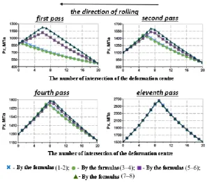
According to the obtained calculation data, the epures of normal contact stresses along the length of the defor-mation center have been built and shown in Figure 3. The obtained diagrams coincide with those reported in the literature [6, 7].
The area of the epure is the total pressure of the metal on the rolls per width unit of the rolling strip. The area of the epures was determined as follows. All the curves of Figure 3 were plotted on a single graph in Mathcad. Then, these graphs were redrawn and the area of the epures was determined in the software complex Auto-CAD Mechanical 2019.
Comparison of the areas of the normal contact stress epures, obtained by simplified formulas (3), (4) and more accurate equations of A. I. Tselikov (1), (2), shows that these areas are almost exactly the same: their maximum difference is no more than 5 %. Therefore, the simplified formulas are equivalent to the accuracy of determining the value of the normal contact stress.
Figure 1 – A block-scheme of calculation of contact stresses during longitudinal rolling of the strips
At the same time, the simplification conducted during the derivation of the differential equation of equilibrium leads to relatively simple formulas, taking into account the change in the forced yield strength, both by the law of a straight line and parabolic law.
5
Discussion
From the above epures, it is noticeable (Table 2) that the maximum difference of their areas by the straight-line law of change of the forced yield strength in the defor-mation center reaches 29 %, and 43 % by the parabolic law, especially in the first passes, when the metal is in-tensively hardened.
Based on the analysis of the contact stress epures, it can be concluded that the most accurate calculation of the total metal pressure on the rolls during cold rolling is possible only when the formulas used to consider the change in the forced yield strength in the deformation center by the law of a straight line or the parabolic law.
E 34 MECHANICAL ENGINEERING: Computational Mechanics
Figure 3 – Epures of normal contact stresses in the passes of a reverse rolling mill 1680
Table 2 – The areas of the normal contact stress epures according to Figure 3
Pass Epure area, mm2, obtained by the formu-las:
The relative difference of the areas of the epures in %, obtained by the formulas (1), (2) (3), (4) (5), (6) (7), (8) (1), (2) (3), (4) (5), (6) (7), (8) І 2346.6 2258.6 3020.8 3361.7 0.00 –3.75 28.73 43.26 ІІ 6629.3 6587.5 6998.3 7334.0 0.00 –0.63 5.57 10.63 IV 8871.8 8829.4 8956.2 9143.6 0.00 –0.48 0.95 3.06 XI 13548.9 13487.1 13566.5 13573.0 0.00 –0.46 0.13 0.18
6
Conclusions
The algorithm, the block-diagram and the computer program of calculation of normal contact stresses in the deformation center during cold rolling of the strips at the reverse mill 1680 PJSC “Zaporizhstal” have been devel-oped with the help of Mathcad Prime 5 software com-plex. The results of the calculations coincide with the
literature data. The epures were constructed and a com-parative analysis of the formulas used to calculate the normal contact stresses in the deformation center was performed. It is shown that the most reliable results can be obtained by using formulas that take into account the change in the forced yield strength in the deformation center, according to the parabolic law.
References
1. Panjkovic, V. (2014). Friction and the Hot Rolling of Steel (2nd ed.). Boca Raton, FL: CRC Press.
2. Lee, W., Kwak, J., Park, C. (1996). A new approach to predict rolling forces in the tandem cold rolling mill. In Proc.2nd Inter-national Conference on Metal Rolling Processes. London, pp. 473–477.
3. Ginzburg, V., Ballas, R. (2000). Fundamentals of Flat Rolling. Marcel Dekker, New York.
4. Hensel, A., Spittel, T. (1982). Kraft-und Arbeitsbedarf bildsamer Formgebungs-verfahren. VEB Deutscher Verlag fur Grund-stoffindustrie, Leipzig.
5. Nikolaev, V. (2018). Napryazheniya, deformatsii i sluzhba valkov v kleti kvarto. Monografiya. ZGIA, Zaporozhe. 6. Nikitin, G. (2009). Teoriya nepreryivnoy prodolnoy prokatki. Uchebnoe posobie. MGTU im. Baumana, Moscow. 7. Himich, G. (1972). Mehanicheskoe oborudovanie tsehov holodnoy prokatki. Mashinostroenie, Moscow.
Journal of Engineering Sciences, Volume 6, Issue 2 (2019), pp. E 31–E 35 E 35 9. Sereda, B., Kruglyak, I., Zherebtsov, A. and Belokon, Y. (2011). The influence of deformation process at titan aluminides
re-trieving by SHS-compaction technologies. Metallurgical and Mining Industry, Vol. 3, pp. 59–62.
10. Vasilchenko, T., Yavtushenko, G., Bondarenko, Y., Belokon, Y. (2015). Calculation of planetary drive of mechanical press.
Metallurgical and Mining Industry, Vol. 7 (12), pp. 178–182.
11. Shestakov, N. (2008). Raschetyi protsessov obrabotki metallov davleniem v Mathcad (reshenie zadach energeticheskim metodom). Uchebnoe posobie. MGIU, Moscow.
УДК 621.771:514.18
Числовий експеримент з розрахунку нормальних контактних напружень
в осередку деформації при прокатуванні штаб
Явтушенко О. В.1, Проценко В. М.1, Бондаренко Ю. В.1, Кириченко О. Г.1, Пінг Ф. Й.2 1 Запорізький національний університет, пр. Соборний, 226, 69006, м. Запоріжжя, Україна;
2 ТОВ «Фуцзянь Сянгсін», Фужоу, Фуцзянь, Китай
Анотація. У статті розглянуто можливості застосування програмного комплексу “MathCAD Prime 5” для розрахунку нормальних контактних напружень в осередку деформації при холодному прокатуванні штаб. Ро-зроблено алгоритм, блок-схему і комп’ютерну програму розрахунку нормальних контактних напружень під час прокатування штаб на реверсивному стані 1680 ПАТ «Металургійний комбінат «Запоріжсталь». Побудо-вано епюри і виконано порівняльний аналіз формул, що використовують для розрахунків нормальних конта-ктних напружень в осередку деформації. Розрахункові дані, отримані за допомогою програмного комплексу “Mathcad Prime 5”, співпадають з літературними даними, що визначає практичну значимість отриманих ре-зультатів для науково-дослідної та проектно-конструкторської робіт. Грунтуючись на аналізі епюр контакт-них напружень, можна зробити висновок, що найточніший розрахунок загального тиску металу на валки під час холодного прокатування реалізується у випадку, коли формули, які визначають математичну модель, ураховують змінювання вимушеної межі текучості в осередку деформації за прямолінійним або параболіч-ним законами. При цьому прямолінійний закон змінювання вимушеної межі текучості може бути використа-ний лише для випадку порівняно невеликих обтиснень. У інших випадках необхідно використовувати фор-мули, що враховують змінювання вимушеної межі текучості за параболічним законом.