Multi-Objective Control of Utility-scale
Variable-Speed Wind Turbines for Drive-train Load
Reduction in Low Wind Speed Regime
Edwin Kipchirchir1*, Jackson G. Njiri2 and Stanley I. Kamau3
1Edwin Kipchirchir, Department Mechatronic Engineering, PAUSTI. 2Jackson G. Njiri, Department of Mechatronic Engineering, JKUAT. 3Stanley I. Kamau, Department of Electrical Engineering, JKUAT.
*Edwin Kipchirchir - Email: [email protected].
Abstract-- Wind turbines are important in capturing power from varying wind speed. For maximum energy capture in low wind speed regime, a standard generator torque controller is normally used to track the incoming wind speed in order to maximize power production. In low wind speed regime, the rotor blade pitch angles are held constant at an optimum value that ensures maximum lift. This control strategy has some limitations, especially in large wind turbines due to induced structural loads. Though aerodynamic loads are not high in the low wind speed regime, maximum power point tracking can cause high torque variations in the drive-train which can lead to early fatigue failure of the wind turbine. Most studies done in this regime focuses on maximum energy capture, without considering structural loads, which are critical in large wind turbines that have large inertial loads. In this paper, a multi-objective control strategy that ensures utility scale wind turbines capture maximum power in low wind speed regime, while minimizing drive-train vibrations is proposed. An optimal generator torque controller is designed to achieve maximum energy capture, while an independent blade pitch controller is designed to reduce drive-train vibrational loads in the wind turbine. The two controllers are designed in MATLAB and simulated in Fatigue, Aerodynamics, Structural and Turbulence (FAST) software. TurbSim full-field turbulent wind simulator is used to generate varying wind profiles for simulation purposes. A fictitious 1.5 MW WindPACT wind turbine model is used to evaluate the proposed control strategy. When evaluated against a baseline controller for the low wind speed regime under stochastic wind excitation, the multi-objective control strategy improves drive-train torsional damping by 2.69%, with standard deviation decreasing by 3.28%, without compromising on power capture.
Index Term-- Horizontal axis wind turbine (HAWT), linear quadratic gaussian (LQG), maximum power point tracking (MPPT), variable-speed wind turbine (VSWT), independent pitch control (IPC), optimal tracking rotor (OTR).
INTRODUCTION
WIND turbines are used to capture power from varying wind speed. Being a renewable source of energy, it reduces reliance on fossil fuel-based energy sources that are harmful to the environment. With time, as the world population grows and economies expand, there is increasingly high demand for energy from renewable sources. Wind is most competitive and preferred renewable energy source due to its minimal negative impact on the environment [1]. This has led to rapid growth in demand for wind energy generation, necessitating wind
turbine manufacturers to produce larger wind turbines. There are increased structural loads with increase in wind turbine size, which is attributed to gravitational loads, inertial, centrifugal, and gyroscopic loads which occur during operation. These structural loads can drastically reduce the lifetime of a wind turbine. Therefore, there is need to design control strategies to reduce structural loads in wind turbines. In a variable speed wind turbine, power production occurs in the low wind speed regime (below the rated wind speed region), and the high wind speed regime (above the rated wind speed region). Most wind turbines operate in the low wind speed regime, whose main objective is to maximize the amount of power extracted by the wind turbine. Therefore, the rotational speed of the generator should be adjusted in real time in relation to the incoming wind speed [2]. The main objective in the high wind speed regime is to regulate the rotor speed and power so as to avoid exceeding mechanical and electrical limits of the wind turbine. To lower the cost of energy production, there is a growing need for energy efficiency for wind turbines operating in the low wind speed regime. This is attained by operating the wind turbine at optimum power efficiency as much as possible. Proper design of controllers for Wind Energy
Conversion Systems (WECS), ensures efficient energy generation, good power quality, and reduced mechanical and aerodynamic loads resulting in increased turbine life [3].
Utility-scale wind turbines normally have Horizontal Axis Wind Turbine (HAWT) configuration due to its advantages over Vertical Axis Wind Turbine (VAWT) configuration. One advantage is being able to mount the entire rotor on top of a tall tower in order to take advantage of higher wind speeds. Variable pitch and speed operation, improved structural performance, and elimination of guy wires used to add structural stability are the other advantages of HAWTs [4].
Speed Wind Turbines (VSWTs) track wind speed variations in order to maximize aerodynamic efficiency in the low wind speed regime. From control perspective, this requires knowledge of complex aerodynamic properties to ensure maximum energy is captured [6]. Given that variable speed wind turbines are able to change their rotational speed to follow instantaneous changes in wind speed, they are able to maintain an optimal Tip Speed Ratio (TSR) at all times [7]. Therefore, VSWTs are able to operate at maximum aerodynamic efficiency for more fraction of time than fixed speed wind turbines, hence
are cost-effective in utility scale applications [8].
Modern utility scale wind turbines are installed with individual blade pitch actuation mechanisms, where control of pitch angle for each blade is done independently to ensure symmetrical loading of the rotor disc. Several sensors are also installed in the blades, tower and nacelle of these wind turbines. According to [9], accelerometers are usually installed in the nacelle to measure tower fore-aft and side-side motion, torque transducers are installed in the Low Speed Shaft (LSS) and High Speed Shaft (HSS), absolute position encoders give information on pitch, yaw, LSS, and HSS positions, and strain gauges are installed in blade roots and towers. In low wind speed regime, Maximum Power Point Tracking (MPPT) can induce mechanical stress on the drive-train system, especially in utility-scale wind turbines. Drive-train vibrations can lead to excitation of poorly damped modes in the turbine which can reduce the service life of a wind turbine [10]. According to a survey done in [11], the main causes of downtime in wind turbines are: Power module, drive-train module, and rotor module. The drivetrain carries some the most critical and expensive components of the wind turbine. Therefore structural load reduction in the drive-train is critical.
In [12], a Sliding Mode-Extremum Seeking Controller (SM-ESC) was proposed. In the study, the control strategy was implemented using PI-based controllers hence, did not account for wind disturbances. Therefore, the MPPT controller performance was degraded under stochastic wind profile. A multi-variable extremum seeking control for maximizing energy capture in VSWTs was implemented in [13], where the optimal control torque and pitch angle are searched by ESC based on the measurement of the rotor power. As opposed to [12] that used only simulated wind profiles, [13] utilized both simulated and field-recorded winds for simulations carried out in FAST software. The developed multi-variable ESC improved turbine operation in fluctuating wind and with actuator saturation, and given addition of anti-windup and input resetting to deal with the integral wind-up, transient performance was improved under sudden changes in wind profile. However, independent pitch control was not implemented.
In the study in [3], a multi-variable controller based on Multiple Model Predictive Control (MMPC) technique for the control of variable speed, variable pitch wind turbines operating low and high wind speed regimes. However, the pitch angle was held constant in the low wind speed regime and only generator torque was controlled. The study in [14]
proposed a multivariable control strategy for VSWTs operating in both low and high wind speed regimes. The developed torque controller was based on achievement of zero speed-tracking error to allow maximum energy capture in the low wind speed regime. However, the study did not incorporate structural load reduction in the control strategy, which is important if multi-objective control is to be implemented. In [4], a multi-variable control strategy for regulating generator power while minimizing rotor blade loads using a 1.5 MW wind turbine used in this paper, operating in the high wind speed regime was implemented. Contrary to [14], the study in [4] incorporated structural load reduction. A baseline PI controller was used to generate collective pitch angle control for generator speed regulation, and an independent pitch controller, which is designed in this paper, was used for structural load reduction in the high wind speed regime. Performance comparison was done between the multi-variable control scheme, and the baseline PI control. The PI controller achieved speed and power regulation, and dampening of tower fore-aft deflection, while the independent pitch controller realized load reduction. However, structural load reduction in low wind speed regime was not explicitly studied.
Most of the studies in the low wind speed regime are focused on maximizing power output by manipulating the rotor blade pitch to an optimum pitching angle to achieve highest possible lift, or generator torque to track incoming wind speed or both independently using SISO controllers [4]. The shortcoming with designing individual controllers for optimum power production and induced mechanical load reduction is that optimizing on one objective could lead to performance degradation of the other [15]. Therefore, in this study, an optimal multi-objective controller for a utility-scale wind turbine operating in the low wind speed regime is designed. The multi-objective strategy has an Independent Pitch Controller (IPC) for reduction of drive-train vibrations, and an optimal generator torque controller for power maximization, ensuring trade-off is achieved.
This paper is outlined as follows: Wind turbine fundamentals and control is discussed in section 2. The wind turbine model is presented in section 3. The overall controller design is explained in section 4. Simulation results demonstrating energy optimization and drive-train torsional damping are presented in section 5. Finally, conclusions are drawn in section 6.
1. FUNDAMENTALS OF WIND TURBINES
[16].
The theoretical maximum aerodynamic efficiency,
C
p for awind turbine is given as
,
w a pP
P
C
(1)where
P
a is the aerodynamic power captured by the rotor andw
P
is the available wind power, which is expressed as,
2
1
3A
P
w
(2)
where
A
is the rotor swept area,
is the air density, and
is the wind velocity.The power extracted by the wind turbine is a product of the aerodynamic efficiency
C
p and the available wind powerw
P
which is given as
,
,
2
1
3p
a
AC
P
(3)
where
is the tip speed ratio (TSR),A
is the rotor swept area, and
is the blade pitch angle. The power coefficient)
,
(
p
C
is a nonlinear function of TSR and blade pitch angle. Tip speed ratio, which is the ratio of the tangential speed of the blade tip to the wind speed is given as,
R
(4)
where
is the rotor speed andR
is the rotor blade radius.For the 1.5 MW WindPACT wind turbine model used in this study, there exists an optimum value of tip speed ratio,
opt and optimum value of pitch angle,
opt that gives a maximum power coefficient,max
p
C
. This is shown in Fig. 1, which gives a tip speed ratio, pitch angle power coefficient curve for the 3-bladed upwind wind turbine model. The 3D plot is shown in Fig. 1 (a), while Fig. 1 (b) shows the maximum power coefficient for a given TSR and blade pitch angle. It can be seen that the wind turbine has amax
p
C
of 0.488, which occurs at an optimum blade pitch angle of 2.6o and a TSR of 7. Thecontrol objective is to ideally operate the wind turbine at the peak of the
C
p curve during power production.Fig. 1. Tip speed ratio, pitch angle power coefficient curve for NREL WindPACT 1.5 MW Turbine [10].
The power extracted is equivalent to the aerodynamic rotor power
,
a aP
(5)where
a is the aerodynamic torque applied to rotor by wind and
is the rotor angular speed. The aerodynamictorque is therefore given by
.
,
2
1
3
2
p aC
R
(6)Given the nonlinear nature of a wind turbine, its modeling is important as it requires that crucial dynamics are captured. The goals in a wind turbine control system includes: Modifying its operating states in order to ensure safety during operation, optimizing power capture, mitigating structural (fatigue and cyclic) loads, and fault detection [9].
Normally, in low wind speed regime operation, commercial wind turbines employ a standard generator torque controller to maximize power generation. As outlined in [8], the standard generator torque control law is given as
,
2
g
K
(7)
where
g is the generator torque and the standard control gainK
, is given by,
2
1
3 5 max opt pC
R
K
(8)where
R
is the rotor blade radius. The optimal tip speed ratioopt
, is the TSR at maximum power coefficientmax
p
C
. Therefore, the generator torque becomes.
2
1
23 5 max
opt p gC
R
(9)Wind speed tracking is achieved by operating the wind turbine at or near the maximum power efficiency
,
max
p
C
, byacceleration or decelerating the rotor so as to track the effective wind speed. Assuming a rigid rotor, i.e. a simplified one mass model of the wind turbine, the rotor angular acceleration is given as
,
1
g a
J
(10)
where
J
is to the total rotational inertia of the rotor, generator, gearbox and drive shafts. From Eqn. (10, it can be seen that at steady state generator torque
g, balances out with the aerodynamic torque
a, otherwise the rotor either accelerates or decelerates to maintain
opt, so asto yield maximum power.
In this paper, a standard torque controller is used as a baseline controller, where the gain K of 0.002585 specified by NREL is used. A representation of the standard generator torque controller connected to the nonlinear wind turbine model is shown in Fig. 2. Generator speed measurement from the nonlinear wind turbine model is used to implement the standard torque control.
Fig. 2. Baseline generator torque controller
Because of its simplicity, this control method is popular. The values of
max
p
C
and
opt are determined by observing thep
C
-TSR-
curve, which is obtained through simulation using aerodynamics codes, or through experiments [9]. The value of gainK
is then approximated numerically or through experiments. However, it has limitation in large wind turbines because wind speed varies spatially over the rotor swept area, hence, the wind turbine operates sub-optimally for the chosenK
. Also, when the rotor speed is strictly tracking incoming wind speed, very high torsional stresses are induced in the drive-train which can lead to early failure of gearbox or shaft components. An Optimal Tracking Rotor (OTR) generator torque controller is designed in this paper to achieve better tracking in stochastic wind conditions.2. WIND TURBINE MODEL
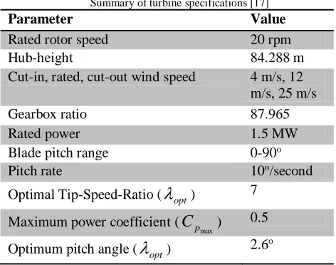
In this paper, a fictitious 1.5 MW WindPACT wind turbine model is used to evaluate the proposed multi-objective control strategy. It is an upwind, 3-bladed, horizontal axis, variable speed and pitch wind turbine. The specifications of this model are summarized in Table 1. The wind turbine model has 24 Degrees of Freedom (DOFs), describing its flexibility.
Table I
Summary of turbine specifications [17]
Parameter Value
Rated rotor speed 20 rpm
Hub-height 84.288 m
Cut-in, rated, cut-out wind speed 4 m/s, 12 m/s, 25 m/s
Gearbox ratio 87.965
Rated power 1.5 MW
Blade pitch range 0-90o
Pitch rate 10o/second
Optimal Tip-Speed-Ratio (
opt) 7Maximum power coefficient (
max
p
C
) 0.5Optimum pitch angle (
opt) 2.6oWind turbines are influenced by spatially varying wind speeds, changing in both speed and direction. This leads to non-linearity and highly coupled modes in the wind turbine whose generalized equation of motion is expressed as
q
,
u
,
t
q
f
q
,
q
,
u
,
u
,
t
0
,
M
d (11)where
M
is the mass matrix containing inertia and mass components andf
is a nonlinear function. The vectorsq
,q
, andq
denotes the enabled DOFs displacements, velocities, and accelerations, respectively. On the other hand,u
is the control input andu
d represents the wind input.In order to design the independent pitch controller for load mitigation, the nonlinear model available in FAST design code is linearized about a given operating point in the low wind speed regime. Choosing the operating point is necessary in order to ensure that the simulation converges to the required trim solution, and also to make use of linear control theory. The chosen operating point is defined by a steady wind of 8 m/s, rotor speed of 14.73 rpm, and optimal pitch angles of 2.6o. The wind speed of 8 m/s is chosen as a midpoint between
cut-in and rated wind speeds of 4 m/s and 12 m/s, respectively. Although the nonlinear wind turbine model has 24 DOFS, only 4 DOFs relating to the desired objectives are enabled in order to extract a linear model from the nonlinear model described by Eqn. (11). This assumed modes approach allows modeling of the most important turbine dynamics with relatively few DOFs [9]. The enabled DOFs includes: Drive-train rotational flexibility,
, and first flap mode deflections of each blade,
1,
2, and
3. The enabled DOFs can written in compact form as
Tq
,
1,
2,
3 . Drive-train rotational flexibility isAccording to [18], linearization is done in two steps. First, a steady state solution of operating point of enabled DOFs is calculated. Secondly, numerical linearization about the resulting steady state is performed to form periodic matrices of a linear model. Periodicity of the linear model is attributed to deterministic loads interacting with the wind turbine during operation. The period for one revolution of the rotor, which is used for linearization is calculated based on the steady state rotor speed of 14.73 rpm, and is found to be 4.07 seconds. Over this period, 24 equispaced azimuth positions are selected for linearization.
After linearization, 24 Linear Time Invariant (LTI) models are generated from the 24 equispaced azimuth steps. The linearized state-space periodic model of the wind turbine is expressed as
,
m m m m d d m m m m m d d m m m m mu
D
u
D
x
C
y
u
B
u
B
x
A
x
(12)where
A
m
is the state matrix,B
m
is the input matrix,
m
C
is the output matrix, andD
m
is the direct transmission matrix. On the other hand,
m
d
B
is the inputdisturbance matrix and
m
d
D
is the direct transmissiondisturbance matrix. The state vector is
x
m
q
,
q
T ,while
u
m
1,
2,
3
Trepresents the perturbed input vector of independent pitch angles. The perturbed hub-height wind speed ism
d
u
, andy
m is the measured output vector having the blade tip deflections and high speed shaft torque. The subscript m denotes that the model is expressed in mixedreference coordinates, since the rotor blades are expressed in the rotating frame and the nacelle components is in the fixed coordinate system.
Averaging the obtained set of 24 linearized state-space periodic models leads to loss of inherent wind turbine periodicity brought about by vertical wind shear and tower shadow, which is necessary for controller design. Periodicity is more pronounced in large wind turbines due to vertical wind shear, tower shadow, and yaw misalignments. Multi-blade coordinate (MBC) transformation, also known as Coleman transformation is a method of transforming degrees of freedom of the rotor from a rotating frame to a fixed frame of reference [19]. Multi-blade coordinate transformation similar to the one described in [20], is employed in this paper. As noted in [21], MBC transformation has been found to reduce variations in the different azimuth linearized models, resulting in an averaged model that depicts turbine dynamics more accurately. Multi-blade coordinate transformation is therefore necessary in order to convert the individual blade dynamics in the rotating coordinate system to a reference coordinate system. This provides a fixed standpoint for controller design. Therefore, MBC transformation is used to integrate the inherent wind turbine periodicity in the LTI model, hence accounting for asymmetrical load variations in rotor blades.
For a 3-bladed upwind HAWT, each blade is directly in front of the tower once per revolution of the rotor. This leads to tower shadow effect, which induces 3p, 6p, etc. harmonic loads to the fixed structure of the wind turbine. The turbine blades on the other hand experience 1p, 2p etc. harmonic loads due to vertical wind shear [4].
For a 3-bladed wind turbine, with enabled DOFs given as
q
i, wherei
1
,
2
,
3
, the expression ofq
i is given as
1
,
3
4
sin
1
3
2
cos
q
q
i
q
i
q
i o c
s
(13)
where
is the azimuth angle,q
o is the conic mode, whilec
q
andq
s are the cosine-cyclic and sine-cyclic modes, respectively. The modes lead to the coupling of the rotor with the rest of the wind turbine. The rotational degrees of freedom
j j j
q
q
q
1,
2,
3 corresponding to thej
th DOF for each blade can be transformed to the nonrotating coordinates
j
s j c j o
q
q
q
,
,
using the transformation matrixT
given as
3
4
sin
3
4
cos
1
3
2
sin
3
2
cos
1
sin
cos
1
T
(14)such that the relationship between the rotating states,
x
r and the non-rating (NR) states,x
NR is given by
NRr
T
x
x
(15)
By making use of Eqn. (14), the dynamic model given in Eqn. (12) can be transformed to periodic model given as
,
m NR m NR d d NR NR NR NR NR d d NR NR NR NR NRu
D
u
D
x
C
y
u
B
u
B
x
A
x
(16)The perturbed disturbance input
m
d
u
is already expressed in the fixed reference coordinate, hence it is not transformed. The obtained LTI model described by Eqn. (16) can be averaged to obtain a LTI model which is weakly periodic about the azimuth position [22]. In this paper, the nonlinear wind turbine used is assumed to be influenced by process noisew
and measurement noisev
both of which are Gaussian white noise satisfying the condition
w
E
v
0
,
E
ww
Q
,
E
vv
R
,
E
T
T
(17)
where
Q
andR
are the state and control input weighting matrices, respectively. The weakly periodic averaged model used in this paper for independent pitch control design is expressed as,
v
u
D
Du
Cx
y
u
B
Bu
Ax
x
d d
d d
(18)
where
x
q
,
q
T is the state vector which is perturbed from the operating point states,u
1,
2,
3
is the control input vector,u
d
w
, andy
is the measured output. MatricesA
,B
,C
, andD
are the state, input, output, and direct transmission matrices, respectively for the weakly periodic LTI model. The input and direct transmission disturbance matrices areB
d andD
d, respectively. In this paper, the matricesB
d,D
, andD
d are not considered in the independent pitch control design.3. CONTROLLER DESIGN
Two controllers are designed to achieve the two objectives of power maximization and structural load reduction in the low wind speed regime. For maximum power extraction, an OTR generator torque controller is designed. An independent pitch controller is designed for damping drive-train vibrations. The controlled variables are perturbed blade pitch angles for the independent pitch controller (IPC) and generator torque for the OTR controller. The performance of the developed multi-objective control strategy is evaluated against standard generator torque controller used for the low wind speed regime. The flowchart used for controller design is given in Fig. 3 which outlines the process used to obtaining the two controllers. The independent pitch controller is obtained from the linearization and MBC transformation process, while OTR controller utilizes generator and rotor speed measurements from the wind turbine model.
In this paper, an OTR generator torque controller proposed in [23] is designed for maximization of power capture. This controller improves wind turbine response by enhancing the turbine rotor’s ability to track the optimal tip speed ratio
opt and hence the incoming wind speed. Optimal tracking rotor control is also more robust in handling errors in selecting optimal TSR either due to improper design or wind turbine blade changes over time caused by residue build-up or corrosion, which results in suboptimal gainK
[15].For optimal tracking rotor control, the standard generator torque is modified to become
2
,
2
g
K
G
a
K
(19)
where is the optimal gain selected to provide a trade-off between acceleration or deceleration rate and other considerations such as prevention of motoring. To implement OTR control in Simulink, the optimal tracking rotor controller is designed such that the gain K is maintained as 0.002585. Generator speed , and rotor torque , are nonlinear wind turbine measurements for OTR controller. The optimal gain G is determined as 0.001 in order to get the value of which is as close as possible to the standard generator torque,
K
2.Fig. 4Fig. 4 shows a representation of the optimal tracking rotor
generator torque control connected to the nonlinear wind
Fig. 3. Flowchart for controller design
turbine. The generator and rotor speed measurements from the wind turbine are fed to the respective control gains, and the obtained generator torque is fed back to the wind turbine.
Fig. 4. Optimal tracking rotor generator torque controller
(18) is used for the design of a Linear Quadratic Gaussian (LQG) controller for independent pitch control. The
A
,B
, andC
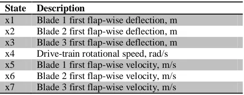
matrices are partitioned in order to make use of the required states and inputs of the nonlinear wind turbine. To meet the required closed-loop performance of the wind turbine with respect to drive-train torsion reduction, the states utilized for LQG controller design are listed in Error! Reference source not found.. The drive-train rotational angle state is eliminated from the linear model used for control design through partitioning ofA
matrix because it is not a wind turbine output measurement. The inputs chosen for controller design are the three commanded blade pitch angles, while the other default inputs used for linearization, including horizontal wind speed, vertical power-law shear exponent, propagation direction, yaw moment, generator torque, and collective blade pitch command are eliminated through partitioning of theB
and
C
matrices.Table II
States contained in the linear model of IPC State Description
x1 Blade 1 first flap-wise deflection, m x2 Blade 2 first flap-wise deflection, m x3 Blade 3 first flap-wise deflection, m x4 Drive-train rotational speed, rad/s x5 Blade 1 first flap-wise velocity, m/s x6 Blade 2 first flap-wise velocity, m/s x7 Blade 3 first flap-wise velocity, m/s
The partitioned matrices;
A
,B
, andC
are used for controller design. In order to design a linear quadratic regulator (LQR), the LTI model has to be controllable. To meet this condition, the controllability matrixQ
c expressed as
B
A
B
A
B
Q
c T Tn1
...
:
:
(20)
should be of full rank. The number of states in the system is
n
. The pair (A
,B
) is tested and found to be controllable. The quadratic objective function given as
x
Qx
u
Ru
dt
J
NR
t T
T0 (21)
is minimized in order to obtain the optimal full-state feedback control gain
K
. The elements of the state weighting matrixQ
, and the control input weighting matrixR
, are tuned so as to provide trade-off between state regulation and control effort. The full-state feedback control law is given as,
1P
B
R
Kx
u
T(22) where
P
is the solution to the algebraic Riccati equation.
0
1
Q
P
B
PBR
PA
P
A
T T(23)
Given that not all states are available for measurement for implementation of full state feedback, an optimal state estimator is necessary. This is accomplished through the design of a Linear Quadratic Estimator (LQE), also known as a Kalman Filter. The condition for LQE design is that the LTI model has to be observable. To meet this condition, the observability matrix
Q
o given as
T T T T T
o
C
A
C
A
C
Q
:
:
...
n1(24)
should be of full rank. The pair (
A
,C
) is tested and found to be observable.The Kalman gain
L
, is designed by minimizing the steady state covariance error given as
T
t
E
x
x
x
x
ˆ
ˆ
lim
(25)
in the presence of system and measurement noise. The elements of the process disturbance covariance matrix
Q
fand measurement covariance matrix
R
f are tuned in order to achieve improved damping in drive-train vibration. The optimal state estimator control is given as,
ˆ
x
K
u
(26)where
x
ˆ
is the estimated state vector andP
f is the solution to the algebraic Riccati equation.
0
1
f f f T f T f
f
P
A
P
C
R
CP
Q
AP
(27)
The Kalman gain is expressed as
L
P
fC
TR
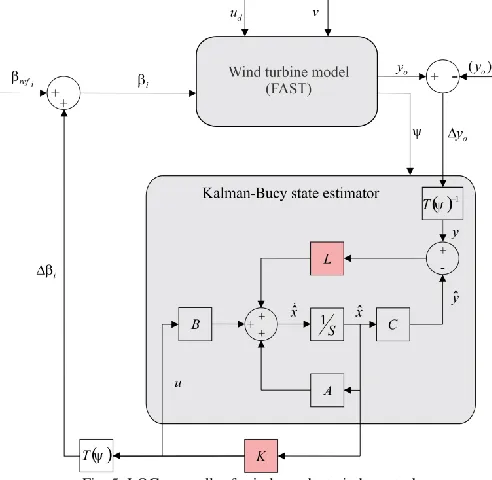
f .A representation of the LQG controller for independent pitch control is shown in Fig. 5. The control parameters including full-state feedback control gain
K
, observer gainL
, and control design matrices,A
,B
, andC
are linked to MATLAB/Simulink in order to simulate the nonlinear wind turbine. The operating point output measurements op
o
y
areobtained by averaging the output measurements of the 24 linear models from linearization. The perturbed outputs
y
, which include: Blade 1,2, and 3 out-of-plane tip deflections, and HSS torque, are transformed to the non-rotating coordinate frame using the inverse of the transformation matrix given in Eqn. (14). Therefore, real-time rotor azimuth position measurement, from the nonlinear wind turbine is used as input to the transformation matrix. The output control signal is transformed back to the rotating coordinate from in order to obtain perturbed pitch angles
i wherei
= 1, 2, 3 isthe blade number. Independent pitch control is achieved by summing
i and the reference pitch angles
refi, andFig. 5. LQG controller for independent pitch control
Although the independent pitch controller is designed using a linear model of the wind turbine, simulation is carried out on the nonlinear wind turbine model. The FAST design code is linked to MATLAB/Simulink using an S-Function block, for simulating the wind turbine with the developed control strategy. Two hub height wind profiles with a vertical power law shear exponent of 0.2, generated using TurbSim turbulent full-field wind simulator are used to excite and simulate the dynamic response of the nonlinear wind turbine. These wind profiles include a step wind varying from 7 m/s to 9 m/s and a stochastic wind profile with mean wind speed of 8 m/s. These wind profiles are shown in Fig. 6.
Standard generator torque control is used as a baseline controller for evaluating the performance of the multi-objective control strategy. To realize baseline control, blade pitch angles are held at an optimum value of 2.6o, while
generator speed output is measured in order to implement torque control. To simulate the developed multi-objective control, the independent pitch and generator torque controllers are realized in the MATLAB/Simulink environment. An instantaneous wind field is used to excite the wind turbine. Selected output measurements from the nonlinear wind turbine are fed to the respective controllers.
Fig. 6. Hub-height wind profiles used to simulation
The degrees of freedom described in Table III are enabled during simulation. In addition to the DOFs used for linearization, the generator DOF is included in order to give additional flexibility to the wind turbine drivetrain. Tower side-to-side deflection DOF is also included so as to evaluate structural loading in the tower.
Table III
Degrees of freedom enabled during simulation
DOF Description
1 Blade 1 first flap-wise mode DOF 2 Blade 2 first flap-wise mode DOF 3 Blade 3 first flap-wise mode DOF 4 Drive-train rotational flexibility DOF
5 Generator DOF
6 First side-to-side tower bending-mode DOF
4. RESULTS AND DISCUSSION
Performance improvements attained using multi-objective control strategy is evaluated against the baseline controller for the nonlinear wind turbine operating in the low wind speed regime. Two wind profiles generated using TurbSim turbulent wind simulation code developed by NREL are used to excite the nonlinear wind turbine dynamics in the low wind speed regime. Given that the independent pitch controller is valid only within small perturbations about the operating point chosen during control design, step and stochastic wind profiles are used to test the control performance for wind speed variations from the design point. Step winds are used to simulate drastic wind speed changes while stochastic winds are used to simulate time-varying wind speeds.
Fig. 7. There is a notable decrease in the mean HSS torque in the multi-objective control strategy when compared to the baseline controller. The multi-objective controller achieves decrease in mean HSS torque of 2.8% and a decrease in standard deviation being 0.32% when compared with the baseline controller. Therefore, the controller achieves better drive-train vibration damping. For better visualization, the time-series data is also converted to frequency domain. Therefore, power spectral density (PSD) plots are conducted. It can be seen that the magnitude of drive-train torsional damping at high frequencies between 7 Hz to 10 Hz, is higher for the multi-objective controller. However, at lower frequencies the baseline controller shows better drive-train torsional damping. At mid frequencies, both the baseline and multi-objective controllers exhibit almost similar drive-train torsional damping levels.
Fig. 7. High speed shaft torque variation under step wind excitation
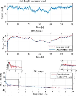
The multi-objective and baseline controllers are also evaluated under stochastic wind excitation as shown in Fig. 8. The multi-objective controller also achieves better drivetrain vibration damping as the mean HSS torque decrease by 2.69% with the standard deviation decreasing by 3.28% when compared with the baseline controller. In frequency domain, it can be seen that the magnitude of drive-train torsional damping at high frequencies between 7 Hz to 10 Hz, is higher for the multi-objective controller. At lower frequencies however, the baseline controller shows better drive-train torsional damping. At mid frequencies, both the baseline and multi-objective controllers exhibit almost similar performance in drivetrain vibration damping.
Fig. 8. High speed shaft torque variation under stochastic wind excitation
Fig. 9. Wind turbine power output under step wind excitation
When the wind turbine is excited with a stochastic wind profile as shown in Fig. 10, power production in the multi-objective controller improves slightly by 0.05%
while standard deviation decreases by 0.8%. Given that the wind turbine has an optimum tip-speed ratio of 0.7, it can be deduced that the there is no compromise in rotor speed tracking the wind speed in order to achieve TSR that is as close as possible to its optimal value. In frequency domain, it can be seen that at low frequencies up to 2 Hz, the multi-objective control strategy exhibits better power capture. Additionally, the multi-objective controller shows lower variations in the magnitude of power captured when compared with the baseline controller at this frequency range. Therefore, the multi- objective controller yields higher quality of power. However, at high frequencies of between 7 Hz and 10 Hz, the baseline controller exhibits better power capture, while at mid-frequencies, between 2 Hz and 7 Hz, the power captured by both controllers is almost identical.
Although improvements in the drive-train torsional damping has been shown in the multi-objective controller, there is need to investigate structural loading in other parts of the wind turbine, like the rotor blades or
Fig. 10. Wind turbine power output under stochastic wind excitation
the tower. Since in-plane blade tip deflection is influenced by drive-train variations, rotor blade in-plane tip deflection is measured during simulation to determine structural loading in the blades. A comparison in in-plane blade tip deflection between the baseline and the multi-objective controllers for the wind turbine under step wind excitation is shown in Fig. 11. Blade deflection increases by 1.87% in the multi-objective controller. This can be attributed to the fact that although there is reduction in HSS torque as well as torsional damping, this energy has to be expended elsewhere, which in this case is in the in-plane blade tip deflection.
Fig. 11. Blade tip deflection under step wind excitation
Fig. 12. Blade tip deflection under stochastic wind excitation
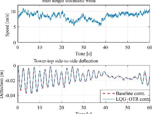
At low wind speeds tower fore-aft deflection is less pronounced. However, tower side-to-side deflection is influenced by variability in the drive-train torque. Therefore, tower-top side-to-side deflection of the wind turbine is measured in order to evaluate the performance of the multi-objective control. For step wind excitation, the comparison is shown in Fig. 13. The multi-objective controller achieves reduction in structural loading as tower deflection decreases by 2.87% when compared with the baseline controller.
Fig. 13. Tower-top side-to-side deflection under step wind excitation
For stochastic wind excitation, the multi-objective controller also achieves reduced loading in the tower, as tower side-to-side deflection reduces by 2.85% when compared with the baseline controller. This comparison is shown in Fig. 14. Therefore, damping in drive-train vibrations leads to reduction in tower side-to-side deflection.
Fig. 14. Tower-top side-to-side deflection under stochastic wind excitation
5. CONCLUSIONS
A multi-objective control strategy is realized in this paper for maximization of power capture and reduction of drive-train loads in large scale wind turbines operating in the low wind speed regime. An optimal tracking rotor controller is designed to replace the standard generator torque controller to improve on power capture. Additionally, an independent blade pitch controller is used to generate perturbed independent pitch angles to aid in damping drive-train torsion. The two controllers are integrated to form a multi-objective controller, which has been shown to achieve the objectives of damping drive-train vibrational loads without compromising on the amount of power captured by the wind turbine. The multi-objective controller handles drive-train structural loads better than the standard generator torque controller. Therefore, it is expected that wind turbine components in the drive-train, which are relatively expensive, will have a longer service life. Although there was a notable increase in structural loading in the rotor blades, this is an acceptable compromise given that blades are flexible components that can handle deflections quite well. The magnitude of the blade deflections are low, especially while operating in the low wind speed regime as wind speeds are moderate. However, the multi-objective controller achieves reduction in tower side-to-side deflection.
In this paper, a multi-objective control strategy is investigated on 1.5 MW onshore wind turbine operating in the low wind speed regime. Although this wind turbine is considered to be utility scale, there is need to test the effectiveness of the control strategy on wind turbines of a larger scale. Additionally, a larger proportion of commercial wind turbines are offshore. Therefore, this study can be extended to offshore wind turbines, which incorporate other dynamics like hydrodynamics, mooring dynamics, and icing effects.
ACKNOWLEDGEMENT
REFERENCES
[1] H. Geng and G. Yang, “Linear and Nonlinear Schemes Applied to Pitch Control of Wind Turbines,” Hindawi Publ. Corp., vol. 2014, no. 406382, pp. 6–8, 2014.
[2] W. M. Lin and C. M. Hong, “Intelligent approach to maximum
power point tracking control strategy for variable-speed wind turbine generation system,” Energy, vol. 35, no. 6, pp. 2440–2447, 2010.
[3] M. Soliman, O. P. Malik, and D. T. Westwick, “Multiple model MIMO predictive control for variable speed variable pitch wind turbines,” Am. Control Conf. (ACC), 2010, vol. 5, no. July 2010, pp. 2778–2784, 2010.
[4] J. G. Njiri, Y. Liu, and D. Söffker, “Multivariable control of large variable-speed wind turbines for generator power regulation and load reduction,” IFAC-PapersOnLine, vol. 28, no. 1, pp. 544–549, 2015.
[5] R. D. Shukla and R. K. Tripathi, “Maximum Power Extraction
Schemes & Power Control in Wind Energy Conversion System,” Int. J. Sci. Eng. Res., vol. 3, no. 6, pp. 1–7, 2012.
[6] K. E. Johnson, L. Y. Pao, M. J. Balas, and J. F. Lee, “Control ot Variable-Speed Wind Turbines: Standard and Adaptive Techniques for Maximizing Energy Capture,” IEEE Control Syst., vol. 26, no. 3, pp. 70–81, 2006.
[7] K. Z. Østergaard, P. Brath, and J. Stoustrup, “Estimation of effective wind speed,” J. Phys. Conf. Ser., vol. 75, no. 1, 2007.
[8] H. Allamehzadeh and M. Ieee, “An Overview of Wind Energy
Technology and Control,” in 2016 IEEE Green Technologies
Conference, 2016, pp. 95–100.
[9] A. D. Wright and L. J. Fingersh, “Advanced Control Design for Wind Turbines Part I : Control Design , Implementation , and Initial Tests Advanced Control Design for Wind Turbines Part I : Control Design , Implementation , and Initial Tests,” National Renewable Energy Laboratory (NREL), vol. NREL/TP-50, no. March. pp. 1– 65, 2008.
[10] J. G. Njiri and D. Söffker, “State-of-the-art in wind turbine control: Trends and challenges,” Renew. Sustain. Energy Rev., vol. 60, pp. 377–393, 2016.
[11] S. Sheng and NREL, “Report on Wind Turbine Subsystem
Reliability - A Survey of Various Databases,” 2013.
[12] T. Pan, Z. Ji, and Z. Jiang, “Maximum Power Point Tracking of Wind Energy Conversion Systems Based on Sliding Mode
Extremum Seeking Control,” 2008 IEEE Energy 2030 Conf., pp. 1–
5, 2008.
[13] J. Creaby, Y. Li, and J. E. Seem, “Maximizing Wind Turbine Energy Capture using Multivariable Extremum Seeking Control,” Wind Eng., vol. 33, pp. 361–387, 2009.
[14] A. Merabet, J. Thongam, and J. Gu, “Torque and pitch angle control
for variable speed wind turbines in all operating regimes,” 2011 10th Int. Conf. Environ. Electr. Eng., vol. 1, no. 2, pp. 1–5, 2011. [15] K. E. Johnson, L. J. Fingersh, L. Y. Pao, and M. J. Balas, “Adaptive
Torque Control of Variable Speed Wind Turbines,” in 43rd AIAA Aerospace Sciences Meeting, 2005, no. January, pp. 1–11. [16] M. A. Abdullah, A. H. M. Yatim, C. W. Tan, and R. Saidur, “A
review of maximum power point tracking algorithms for wind energy systems,” Renew. Sustain. Energy Rev., vol. 16, no. 5, pp. 3220–3227, 2012.
[17] D. J. Malcolm, “WindPACT Turbine Rotor Design Study
WindPACT Turbine Rotor Design Study,” 2006.
[18] B. Jonkman and J. Jonkman, “FAST modularization framework for
wind turbine simulation: full-system linearization,” J. Phys. Conf. Ser., vol. 753, 2016.
[19] L. C. Henriksen, N. K. Poulsen, and H. H. Niemann, “Constraint Handling within a Multi-blade Coordinate Framework of a Wind Turbine,” in 2011 50th IEEE Conference on Decision and Control and European Control Conference (CDC-ECC), 2011, no. 1, pp. 5825–5830.
[20] G. Bir, “User ’ s Guide to MBC3 : Multi-Blade Coordinate
Transformation Code for 3-Bladed Wind Turbines,” 2010.
[21] J. Laks, L. Pao, A. Wright, N. Kelley, and B. Jonkman, “The use of
preview wind measurements for blade pitch control,” Mechatronics, vol. 21, no. 4, pp. 668–681, 2011.
[22] J. G. Njiri, N. Beganovic, M. H. Do, and D. Söffker, “Consideration
of lifetime and fatigue load in wind turbine control,” Renew. Energy, vol. 131, pp. 818–828, 2019.
[23] L. J. Fingersh and K. E. Johnson, “Baseline Results and Future
Plans for the NREL Controls Advanced Research Turbine,” in 42nd
AIAA Aerospace Sciences Meeting and Exhibit, 2004, no. January, pp. 1–7.
![Fig. 1. Tip speed ratio, pitch angle power coefficient curve for NREL WindPACT 1.5 MW Turbine [10]](https://thumb-us.123doks.com/thumbv2/123dok_us/1350074.1643463/3.612.319.563.55.166/speed-ratio-pitch-angle-power-coefficient-windpact-turbine.webp)