Volume 1, Issue 4 (September2012) PP: 39-46
The Application of PSO to Hybrid Active Power Filter Design for
3phase 4-Wire System with Variable Load
B. Suresh Kumar
1, Dr. K. Ramesh Reddy
2Abstract––An optimal design method for and hybrid active power filters (HAPFs) set at high voltage levels to satisfy the requirements of Harmonic filtering and reactive power compensation. Multi objective Optimization models for HAPF were constructed. Detuning effects and faults were also considered by constructing Constraints during the optimal process, which improved the reliability and practicability of the designed filters. An effective Strategy was adopted to solve the multi objective optimization Problems for the designs of HAPF. Furthermore, the Particle swarm optimization algorithm was developed for searching an optimal solution of planning of filters. An application of the method to an industrial case involving harmonic and reactive Power problems indicated the superiority and practicality of the proposed design methods.
I.
INTRODUCTION
POWER Systems have to cope with a variety of nonlinear Loads which introduce significant amounts of harmonics. IEEE Standard 519-1992 provides a guideline for the limitation and mitigation of harmonics. Passive power filters (PPFs), Active power filters (APFs), and hybrid active power filters (HAPFs) can all be used to eliminate harmonics. For Medium- and high-voltage systems, PPFs and HAPFs appear to be better choices considering cost where the ratings are of several tens of megavolt–amperes. The design of such PPFs and HAPFs is a complicated nonlinear programming problem. Conventional trial-and-error Methods based on engineering experience are commonly used, but the results are not optimal in most cases.
In recent years, many studies have appeared involving optimal PPF design. A Method based on the sequential unconstrained minimization Technique has been used for PPF design because of its simplicity and versatility, but numerical instability can limit the application of this method. PPF design using simulated Annealing has been reported, but the major drawback is the repeated annealing.
Genetic algorithms (gas) have been widely used in PPF design, but the computing burden and convergence problems are disadvantages of this approach. A design method for PPFs using a hybrid Differential evolution Algorithm has also been proposed, but the algorithm is Complex, involving mutation, crossover, migrant, and accelerated
Operations For the optimal design of HAPFs, a method based on gas has been proposed in order to minimize the rating of APF, but no other optimal design methods appear to have been Suggested. Many methods treated the optimal design of PPFs and HAPFs as a single objective problem. In fact, filter Design should determine the optimal solution where there are multiple objectives. As these objectives generally conflict with One another, they must be cautiously coordinated to derive a Good compromise solution.
In this paper, optimal multi objective designs for both PPFs and HAPFs using an advanced particle swarm optimization (PSO) algorithm are reported. The objectives and constraints were developed from the viewpoint of practicality and the Filtering characteristics.
For the optimal design of PPFs, the capacity of reactive Power compensation, the original investment cost, and the total Harmonic distortion (THD) were taken as the three objectives. The constraints included individual harmonic distortion, fundamental Reactive power compensation, THD, and parallel and Series resonance with the system. For the optimal design of HAPFs, the capacity of the APF, The reactive power compensation, and the THD were taken as the three objectives; the constraints were as for the PPFs.
The Uncertainties of the filter and system parameters, which will Cause detuning, were also considered as constraints during the optimal design process. A PSO-based algorithm was developed to search for the optimal solution. The numerical results of case Studies comparing the PSO method and the conventional trial and- Error method are reported. From which, the superiority and Availability of the PSO method and the designed filters are certified.
II.
SYSTEM UNDER STUDY
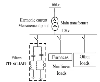
Furnaces Other loads Nonlinear
loads Filters
PPF or HAPF
Main transformer Harmonic current
Measurement point
10kv 66kv
Fig 1. Single diagram of system for case studies.
TABLE I : HARMONIC CURRENT DISTRIBUTIONS IN PHASE A AND UTILITY TOLERANCES Harmonic
Order
Measured Value
(%)
National Standard
(%)
IEEE standard 519-1992
(%)
5 6.14 2.61 4
7 2.77 1.96 4
11 1.54 1.21 2
13 0.8 1.03 2
17 0.6 0.78 1.5
19 0.46 0.7 1.5
23 0.95 0.59 0.6
25 0.93 0.53 0.6
THD 7.12 5 5
as shown in Table I. The utility harmonic tolerances given in IEEE Standard 519-1992 and the Chinese National Standard GB/T14549-93 are listed in Table I as percentages of the fundamental current. Table I shows that current THD, and the 5th, 23rd, and 25th order harmonic currents exceed the tolerances based on both standards. In addition, the 7th and 11th order harmonics exceed the tolerance based on the National standard.
Filters must therefore be installed to mitigate the harmonics sufficiently to satisfy both standards. Both PPF and HAPF are suitable and economical for harmonic mitigation in such systems. For this system with nonlinear loads as medium frequency furnaces, the even and triple harmonics are very small and far below the standard values, so these harmonics are not considered. In addition, the harmonic voltages are in fact very small, so the voltages are assumed to be ideal.
The fundamental current and reactive power demands are 1012 A and 3–4 MVar, respectively. The short circuit capacity is 132 MVA, and the equivalent source inductance of the system is 2.4 mH
III.
HAPF DESIGN BASED ON PSO
A. HAPF Structure and Performance:
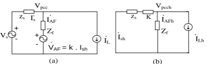
In order to demonstrate the optimal design method of HAPFs based on PSO, an HAPF was designed and is shown in Fig. 2; it is supposed to be used in the same situation as that shown in Fig. 1. In this HAPF, PPFs are mainly used to compensate for harmonics and reactive power, and an APF is used to improve the filtering performance .The PPF consists of the fifth and seventh single-tuned filters and a high-pass damped filter. The APF is implemented with a three-phase voltage-source inverter. Fig. 3(a) shows the single-phase equivalent circuits of the
HAPF, assuming that the APF is an ideal controllable voltage VAF and that the load is an ideal current source IL. ZS is the source impedance, ZF is the total impedance of the PPF, Vpcc is the voltage of the injected point, and K is the controlling gain of the APF.
C5 C7 CH
L5 L7 LH RH
PPF
Nonlinear
loads System source
Ls
Vs
10kv bus
Coupling Transformer
APF
L C
R C
C7
L7 LH
C7
L7 LH
Vpcc zs Is
Zf Vs
VAF = k . Ish + -. + -. . IL IAF . Vpcch zs Zf . IAFh K Ish . ILh . (a) (b)
Fig 3.Single-phase equivalent circuits of the HAPF (a) Equivalent circuit. (b) Equivalent harmonic circuit.
The equivalent harmonic circuit is redrawn as in Fig. 3(b). The harmonic current Ish into the system source and the
harmonic attenuation factor γ are given in the following equations:
| | (1)
| | (2)
F
sh Lh
F S
Sh F
Lh F S
Z
I I
K Z Z
I Z
I K Z Z
Assuming that the fundamental component of the supply voltage is fully dropped across the PPF, the voltage and current of APF can be derived as follows [24]:
1
.
.
(3)
(4)
AF AFh Fh AFh Fh Lh
h h h
AF AF AFh
h
V
V
Z
I
Z
I
I
I
I
The rms value of ˙VAF is defined as2 5,7,11,13,17,19,23,25 (5) AF AFh h V V
The capacity of the APF is determined by the current I˙AF and the voltage ˙VAF. It is obvious that the low VA rating of APF can be achieved by decreasing ˙ IAF and ˙VAF. In this shunt hybrid topology, the current I˙AF is almost constant, so the
only way to reduce the VA rating of APF is to decrease the voltage VAF.
B. Multi objective Optimal Design Model for HAPF:
As mentioned earlier, when designing an HAPF, it is very important to minimize the capacity of the APF component, and there are some other objectives and constraints to be considered when the APF of the HAPF is cut off due to faults, the PPF part keeps work in to mitigate harmonics until the APF is restored. It follows that some additional constraints should be included in respect of such occasions. The constructions of objective functions and constraints are described next.
Three important objective functions are defined as follows.
1) Minimize the capacity of the APF, which is mainly determined by the harmonic voltage across it 2
5,7,11,13,17,19,23,25
min
AF AFh(6)
h
V
V
2) Minimize the current THD with HAPF
2 2 1
min
(7)
N sh HAPF hI
THDI
I
where THDIHAPF is the current THD with the HAPF in place; and the definitions of Ish, I1, and N are the same as those in (7).
3) Maximize the reactive power compensation
5,7,
max
i(8)
i H
Q
Where Qi is same with that in (9)
Constraints are defined as follows.
The tolerated values quoted hereinafter are also based on the National standard. 1) Requirements of total harmonic filtering with the HAPF
(9)
HAPF MAXTHDI
THDI
Where THDIMAX is defined in (10)
When PPF runs individually with the APF cutoff, an additional constraint is added as follows: (10)
PPF MAX
THDI THDI
2) Requirements of individual harmonic filtering with HAPF and PPF alone: Each order harmonic should satisfy the standards, so the following constraints are included:
max max
, 5,7,11,13,17,19, 23, 25 (11)
, 5,7,11,13,17,19, 23, 25 (12)
sh sh
HAPF h
PPF h
I I h
I I h
Where IHAPFsh and IPPFshare, respectively, the rms values of the hth order harmonic current into the system source with the
HAPF and the PPF alone Ihmax is defined by (11).
3) Fundamental reactive power compensation limits: The fundamental reactive power must be restricted as
min max
5,7,
(13)
i
i H
Q
Q
Q
Where Qmin and Qmax are as defined in (12).
4) Parallel and series resonance restrictions: Parallel and series resonance with system source will rarely happen for the HAPF due to the active damping function of the APF. Nevertheless, it is necessary to consider, during the HAPF design, parallel and series resonance restrictions when PPF works alone with the APF cutoff. Therefore, constraints are constructed, which are the same as those constructed during the PPF optimal design in (13)–(16).
5) Consideration of the detuning constraints: The HAPF system is not sensitive to detuning effects because of the APF damping function. In the worst case, that the system impedance decreases by 20%, the system frequency changes to 50.5 Hz, the capacitance of each branch increases by 5%, and the reactance also increases by 2%, then the filtering performance of the PPF alone should still satisfy all the standards and limit described earlier, as set out in (10), (12), and (13).
C. Optimal Design for HAPF Based on PSO Based
on the objectives and constraints constructed earlier for HAPF, the multi objective optimization task is carried out using an advanced PSO algorithm. The capacitance in each branch of the PPF and the characteristic frequency of the high-pass damped filter are chosen as optimal variables Xi = (C5, C7, CH, fH)T, while the tuning frequencies of the fifth and seventh single-tuned filters are predetermined as 242 and 342 Hz, respectively. According to the optimization objectives, the corresponding fitness functions are defined as
' 1 ' 2 ' 3 5,7,
( ) (14)
( ) (15)
( ) (16)
AF
HAPF
i
i H
F X V F X THDI F X Q
Similar methods were adopted to solve this multi objective optimization problem. The objective of minimizing the APF capacity is chosen as the final objective, while the other two objectives are solved by using acceptable level constraints, as shown in the following equations:
1
2 1
2 3 3
min (17) (18) (19) F F F
Whereα’1,α’3,and α’2 are the highest and lowest acceptable levels for the secondary objectives, respectively. The overall
optimization process for the HAPF based on PSO is similar to that of the PPF in Fig. 4.
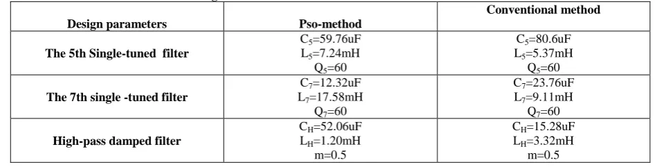
TABLE II : Design results of HAPFs based on PSO and conventional methods
Design parameters Pso-method
Conventional method
The 5th Single-tuned filter
C5=59.76uF
L5=7.24mH
Q5=60
C5=80.6uF
L5=5.37mH
Q5=60
The 7th single -tuned filter
C7=12.32uF
L7=17.58mH
Q7=60
C7=23.76uF
L7=9.11mH
Q7=60
High-pass damped filter
CH=52.06uF
LH=1.20mH
m=0.5
CH=15.28uF
LH=3.32mH
TABLE III: HARMONIC CURRENT DISTRIBUTIONS WITH HAPFs BASED ON PSO AND CONVENTIONAL METHODS
Harmonic orders
PSO Method
(%)
Conventional Method
(%)
5 0.24 0.17
7 0.24 0.11
11 0.25 0.71
13 0.1 0.3
17 0.07 0.16
19 0.06 0.12
23 0.13 0.26
25 0.13 0.26
THD 0.48 0.91
VAF
116.64 V 340.82 V
Reactive Power
Compensation 4MVar 3.88MVar
The design results of HAPFs using PSO and conventional trial-and-error methods are listed in Table II. The design results based on the conventional method in Table II .It can be seen that the harmonic currents and reactive power are well compensated by both HAPFs and that the HAPF designed using the method based on PSO can obtain better filtering performance with lower THD (0.48%) and larger reactive power compensation (4MVar). Moreover, the voltage VAF of the APF, in this case, was much smaller than that based on conventional method. Therefore, the investment cost of the whole system is much reduced. Table IV shows the harmonic current distributions when the PPF is working alone, without the APF.
A comparison is made between the PSO method and conventional method, and it can be seen that all the harmonic currents and the THD are still within the standards, and the filtering performance of PPF based on PSO is a little better.
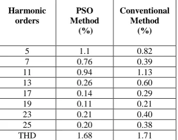
TABLE IV: Harmonic current distributions with PPFs alone Based on PSO and conventional methods
Harmonic orders
PSO Method
(%)
Conventional Method
(%)
5 1.1 0.82
7 0.76 0.39
11 0.94 1.13
13 0.26 0.60
17 0.14 0.29
19 0.11 0.21
23 0.21 0.40
25 0.20 0.38
THD 1.68 1.71
TABLE V :HARMONIC CURRENT DISTRIBUTIONS WITH HAPFS AND PPFS ALONE CONSIDERING DETUNING EFFECTS
Harmonic Orders
PSO Method PPF (%)
PSO Method HAPF (%)
Conventional Method HAPF (%)
5 2.56 0.65 0.44
7 1.72 0.75 0.27
11 0.99 0.23 0.71
13 0.30 0.1 0.27
17 0.17 0.08 0.16
19 0.13 0.06 0.13
25 0.25 0.14 0.28
THD 3.31 1.05 1.02
In order to verify the filtering performances of HAPF and PPF alone under the worst detuning situations, comparisons are shown in Table V. It is clear that both HAPFs, using PSO method and conventional method, can obtain excellent filtering performance in spite of detuning effects.
When PPF runs alone without APF, the PPF using the PSO method can still mitigate all the harmonic currents and THD within the tolerance, while with the PPF using the conventional method, the 11th order harmonic current exceeds the tolerance of the National standard.
These results again verify the necessity of considering detuning effects during the design process. Fig. 4 shows the harmonic attenuation factors of HAPF and PPF alone using the PSO design method and considering detuning effects. It can be seen that the harmonic currents are still well attenuated, and no resonance point can be found. Furthermore, the attenuation factor of HAPF is much smaller than that of PPF, which shows the excellent harmonic mitigation performance of HAPF.
The simulation using the MATLAB/SIMULINK software has been run based on field measurement data., The compensated source current with the HAPF is shown in Fig. 5. From Fig. 5, we can see that the source current is very close to a pure sine wave, with the current THD decreasing to 0.48%.
Fig. 6 shows the convergence characteristics of the PSO algorithm developed in this paper for optimal design of HAPF. In this paper, the PSO algorithm is run 200 times, and every time, it can converge within 360 iterations. All those can demonstrate the efficiency and validity of PSO for the optimal HAPF design.
Fig 4. Harmonic attenuation factors of the HAPF and its PPF alone based on the PSO method.
(a) Harmonic attenuation factor of the HAPF based on the PSO method. (b) Harmonic attenuation of the PPF alone based on the PSO method
Fig.6. Convergence characteristics of PSO for HAPF design.
Table: VI Results with Variable Load
SCHEME
WITH PSO
WITHOUT PSO
% THD P.F
Reactive Power (VAR)
% THD
P.F Reactive Power (VAR)
HAPF 0.47 0.99 2.018 26.54 0.528 1.31
IV.
CONCLUSION
A novel hybrid APF with injection circuit was proposed. Its principle and control methods were discussed. The proposed adaptive fuzzy-dividing frequency control can decrease the tracking error and increase dynamic response and robustness. The control method is also useful and applicable to any other active filters. It is implemented in an IHAPF with a 100-kVA APF system in a copper mill in Northern China, and demonstrates good performance for harmonic elimination. Simulation and application results proved the feasibility and validity of the IHAPF and the proposed control method.
REFERENCES
1. L. Gyugyi and E. C. Strycula, “Active ac power filters,” in Proc. IEEE, Ind. Appl. Soc. Annu. Meeting, 1976, pp.
529–535.
2. N. Mohan, H. A. Peterson, W. F. Long, G. R. Dreifuerst, and J. J. Vithayathil, “Active filters for AC harmonic suppression,” presented at the IEEE Power Eng. Soc. Winter Meeting, 1977.
3. F. Peng, H. Akagi, and A. Nabae, “A new approach to harmonic compensation in power system-a combined system of shunt passive and series active filters,” IEEE Trans. Ind. Appl., vol. 26, no. 6, pp. 983–990, Nov. 1990.
4. C. Madtharad and S. Premrudeepreechacharn, “Active power filter for three-phase four-wire electric systems using neural networks,” Elect. Power Syst. Res., vol. 60, no. 2, pp. 179–192, Apr. 2002.
5. H. Fujita and H. Akagi, “A practical approach to harmonic compensation in power system-series connection of passive and active filters,” IEEE Trans. Ind. Appl., vol. 27, no. 6, pp. 1020–1025, Nov. 1991.
6. H. Fujita and H. Agaki, “The unified power quality conditioner: the integration of series and shunt-active filters,”
IEEE Trans. Power Electron., vol. 13, no. 2, pp. 315–322, Mar. 1998.
7. K. J. P. Macken, K. M. H. A. De Brabandere, I. J. L. Dnesen, and R. J. M. Belmans, “Evaluation of control
algorithms for shunt active tillers under unbalanced and nonsinusoidal conditions,” in Proc. IEEE Porta Power Tech. Conf., Porto, Portugal, Sep. 10–13, 2001, pp. 1621–1626.
8. F. Ruixiang, L. An, and L. Xinran, “Parameter design and application research of shunt hybrid active power filter,”
Proc. CSEE, vol. 26, no. 2, pp. 106–111, Jun. 2006.
9. S. Kim and P. N. Enjeti, “A new hybrid active power filter (APF) topology,” IEEE Trans. Power Electronics, vol.
17, no. 1, pp. 48–54, Jan. 2002.
10. S. Bhattachaya, P.-T. Cheng, Deep, and M. Divan, “Hybrid solutions for improving passive filter performance in high power applications,” IEEE Trans Ind. Appl., vol. 33, no. 3, pp. 732–747, May 1997.
11. L. Malesani, P. Mattavelli, and P. Tomasin, “High performance hysteresis modulation technique for active filters,”
IEEE Trans. Power Electron., vol. 12, no. 5, pp. 876–884, Sep. 1997.
12. S. Fukuda and R. Imamura, “Application of a sinusoidal internal model to current control of three-phase utility-interface converters,” IEEE Trans. Ind. Electron., vol. 52, no. 2, pp. 420–426, Apr. 2005.
13. X. Yuan, W. Merk, H. Stemmler, and J. Allmeling, “Stationary-frame generalized integrators for current control of active power filters with zero steady-state error for current harmonics of concern under unbalanced and distorted operating conditions,” IEEE Trans. Ind. Appl., vol. 38, no. 2, pp. 523–532, Mar. 2002.
14. K. Nishida, Y. Konishi, and M. Nakaoka, “Current control implementation with deadbeat algorithm for
three-phase current-source active power filter,” Proc. Inst. Elect. Eng., Electr. Power Appl., vol. 149, no. 4, pp. 275–282, Jul. 2002.
15. J. H. Marks and T. C. Green, “Predictive transient-following control of shunt and series active power filters,” IEEE
Trans. Power Electron., vol. 17, no. 4, pp. 574–584, Jul. 2002.
16. A. Nakajima, K. Oku, J. Nishidai, T. Shiraishi, Y. Ogihara, K. Mizuki, and M. Kumazawa, “Development of