MODELING OF A NOVEL FUZZY BASED
OVERCURRENT RELAY USING SIMULINK
®
Md. Aminur Rahman, Kazi Main Uddin Ahmed, Md. Rayhanus Sakib
Abstract— In modern protection system the key challenge is the trade-off between the security demand (no false tripping), the speed of operations and the dependability requirements. To meet this challenge properly, the application of a novel Artificial Intelli gence (AI) method, using fuzzy logic, in power system protection has been proposed in this paper along with the simulated data. The examined technique based on fuzzy logic and value estimation to control the protection action of the protective relay was intended to improve the perform ance of a conventional protective relay control for human safety and system reliability with the use of a fuzzy logic controller. The difference between estimated and sampled values was used to form the rule base. Proposed relay architecture was used as a detector and was devel oped to predict faults and to protect particular sections of a designed prototype radial power system at an early stage. Performance analysis of the developed model is simulated using Simulink® and found satisfactory output.
Index Terms— overcurrent relay, fuzzy logic, protection system, relay architecture, simulink®
, artificial intelligence.
————————————————————
1 INTRODUCTION
ELECTRIC power systems are made up of facilities and equipment that generate, transmit and distribute electrical energy. Electric power systems are one of the largest and more complex systems man has ever built. The importance of the services that power systems offer and the high amount of investments that represent the facilities and equipments, make the normal and constant operation of power systems critical and strategic for every society. Faults and failures normally occur in power systems. Due to the great amounts of energy involved, faults represent a threat to the operation and security of power systems if the faults are not promptly corrected. Research in the field of protection and protective relaying techniques of power systems have increased rapidly in the past decade. The basis of these techniques is to measure voltage, current, phase angle, frequency, impedance, etc. between the fault points and relay position, where fault is determined to be either internal or external.
To achieve fast and reliable distance protection many techniques have been developed [2, 3]. One of the most important equipments employed in the protection of power systems are protective relays. These are one of the most flexible, economic and well-known devices that provide reliable, fast and inexpensive protection. Relay is defined by the IEEE as “an electric device that is designed to interpret input conditions in a prescribed manner, and; after specified conditions are met, to respond to cause contact operation or similar abrupt changes in associated electric control circuits [1]”. The brief discussion on the related recent works is gathered in the literature review section. In this study, a novel approach based on fuzzy logic and value estimation was investigated in order to protect the power system against faulty conditions and to control the protective relay. A prototype radial power system was designed and the proposed approach was applied to the prototype system. The proposed relay was developed using conventional protective relay characteristics by adding some abilities such as improved human safety and system reliability, distinguishing whether the fault was transient or permanent, and determining correct action. The prototype experimental setup consisting of a single phase was developed as a radial system and was tested for the proposed method, and satisfactory results were obtained.
2 Basic of Fuzzy logic
The examined technique based on fuzzy logic and value estimation to control the protection action of the protective relay was intended to improve the performance of a conventional protective relay control for human safety and system reliability with the use of a fuzzy logic controller. The difference between estimated and sampled values was used to form the rule base. Proposed relay architecture was used as a detector and was developed to predict faults and to protect particular sections of a designed prototype radial power system at an early stage. Performance analysis was made, and related results and discussion were given. The proposed relay was developed using conventional protective relay characteristics by adding some abilities such as improved human safety and system reliability, distinguishing whether the fault was transient or permanent,
————————————————
Md. Aminur Rahman is currently working as Lecturer of the Dept. of Electrical and Electronic Engineering in Ahsanullah University of Science and Technology, Bangladesh. He Received his B.Sc. in Electrical and Electronic Engineering from Ahsanullah University of Science and Technology, Bangladesh in 2011. E-mail: [email protected]
Kazi Main Uddin Ahmed is currently working as Technical Support manager, Devnet, Bangladesh. He Received his B.Sc. in Electrical and Electronic Engineering from Ahsanullah University of Science and Technology, Bangladesh in 2011.
E-mail: [email protected]
and determining correct action. The prototype experimental setup consisting of a single phase was developed as a radial system and was tested for the proposed method, and satisfactory results were obtained. Fuzzy Inference Systems (FIS) employ the theory of fuzzy sets and fuzzy if-then rules to derive an output. Various types of FIS are often used either for fuzzy modeling or fuzzy classification purposes. Typically a FIS scheme performs its action in several steps including (Fig.1)
1. Fuzzification (comparing the input values with membership functions to obtain membership values of each linguistic term)
2. Fuzzy reasoning (firing the rules and generating their fuzzy or crisp consequents)
3. Defuzzification (aggregating rule to produce a crisp output). [7]
The theory of fuzzy sets has met considerable approval for the sake of ability to describe quantitatively the uncertainties appearing during the operation of a protective relay. Implementation of fuzzy criteria signals together with fuzzy settings brings antidotes to uncertainties caused by dynamic measurement errors and may constitute a remedy against problems related with sharp boundaries in the universe of criteria signals between areas of faulty and failure-free operation of protected plant. Sample applications of this approach to power system protection include fault type identification and multi-criteria protection of power transformers
3 LITERATURE REVIEW ON MODELING OF
PROTECTION SYSTEMS
Relay models have been used for a long time by manufacturers, consultants and academics for designing new prototypes and algorithms, to check and optimize the performance of relays already installed in power systems and to train new protection personnel. Relay manufacturers were the first to develop relay models for evaluating the performance of their designs. Those models implemented the processes by substituting the values of inputs in equations representing the relays to check if the outcomes were acceptable. The characteristics of over current relays were the first to be modeled. Research in the field of protection and protective relaying techniques of power systems have increased rapidly in the past decade. The basis of these techniques is to measure voltage, current, phase angle, frequency, impedance, etc. between the fault points and relay position, where fault is determined to be
either internal or external. To achieve fast and reliable distance protection many techniques have been developed [2, 3]. One of the most important equipments employed in the protection of power systems are protective relays. These are one of the most flexible, economic and well-known devices that provide reliable, fast and inexpensive protection. Relay is defined by the IEEE as “an electric device that is designed to interpret input conditions in a prescribed manner, and; after specified conditions are met, to respond to cause contact operation or similar abrupt changes in associated electric control circuits [1]” Relay manufacturers were the first to develop relay models for evaluating the performance of their designs. Those models implemented the processes by substituting the values of inputs in equations representing the relays to check if the outcomes were acceptable. The characteristics of overcurrent relays were the first to be modeled. Mathematical models [4], [5] were developed in the form of algebraic equations for representing time-current characteristics of overcurrent relays. The first transient model of a distance relay was presented in [6], where the ninth-order state space mathematical model of a mho element was developed.
4 SYSTEM MODEL AND PROPOSED METHOD
Relaying is a subdivision of power system protection engineering that is interested in determining abnormal operating conditions and obtaining corrective events for power system protection. Since human interference to the power system is not possible when a fault occurs, a fast response has the most important role in protective relay systems. The produced response has to be in a form that will cause the minimum damage to the power system. To accomplish this, a prototype power system was designed and the proposed method was applied to the developed radial power system model. System structure of the prototype power system model was shown in Fig.2 The first three blocks in Fig.2 i.e. analogue filters, A/D converters and digital signal processing unit, are typically applied in contemporary digital protection relays.At the output of this path certain criterion values are issued, basing on which the protection decision is to be worked out, usually by their comparison with pre-set thresholds or characteristics. Here, additional signal processing is performed to obtain fuzzified criterion signals (Fig
Fig Block scheme of the FL-based OC protection Fig.1: Basic structure of a fuzzy reasoning system
Decision making Fuzzification
Defuzzification
Fuzzy Setting Input Signal
In the proposed and designed relay architecture, a novel value estimation method was used as opposed to previous works. It is essential in this method to estimate the voltage value at (t+2) sampling instant. The estimated voltage value was formed by using the previously sampled values, which belong to the values at (t+1) and (t) sampling instant. The proposed method had no dependency on sampling interval and sampling frequency. To establish a relationship between estimated and previously sampled values, a mathematical expression was defined as in Eq.1
…..1
Where A is the magnitude of sampled value and x(.) is the sampled value related to sampling instant. Using the above algorithm, the expected value was estimated before the (t+2) sampling was done. A closed loop was constructed for all values to obtain continuous operation. Error and change of error between sampled and estimated value were used as input values for the fuzzy logic controller [7].
Mathematical expressions of the error and change of error were given in Eq.2 and Eq.3
……. (2)
………....… (3)
For the pre-fault conditions, the following assumptions were made:
1. The pre-fault conditions are normal steady-state ones.
2. The source impedances were omitted.
3. Fault impedance and neutral impedance were omitted for all faulted cases.
5 SIMULATION IN SIMULINK
®Simulink® is simulation software which is part of the Matlab ® family. Simulink® is software for modeling, simulating, and analyzing dynamic systems. Simulink® supports linear
and nonlinear systems, modeled in continuous time, sampled time, or a hybrid of the two. Systems can also be multi-rate — having different parts that are sampled or updated at different rates .To simulate the particular problem various Simulink® block was used including the default Simulink® block. Other blocks are
1. SimPower System 2. Fuzzy logic Toolbox 3. Signal Processing Blockset
5.1 About the circuit
The fuzzy based over current relay can sense the fault by analyzing the voltage of the transmission line. The relay not only can sense normal Phase-Ground fault but also it can also tell the different between the permanent and transient fault. The transient period can be defined by the user. For example 1.5 cycle (30ms) or 10 cycle (0.2sec). If the processor is capable to handle the sampled data the system can sense the fault in just 2 samples after the fault. So if a 1000sample/sec sampler is used, the system can sense the fault in 2ms, in case of using an 8000sample/sec the sampler will sense in 250µsec after the fault. So the fuzzy based relay’s speed depends on the sampler speed and how fast the processor can processes the data. So the main features of the relay are:
1. Very fast
2. Actuating Quantity of the relay is voltage change. 3. No complicated mathematical transformation is
required.
4. Can differentiate between transient and permanent fault
5. The transient time can be adjusted easily
5.2 The system
1. The system can be divided in 4 major parts. 2. Voltage Sensing and estimation part 3. Error and Change of error calculation
4.
Fuzzy Processer5.
Logic for transient detection
Fig Sample current amplitude signal with respective fuzzy values (for two selected time intervals).
𝜖 𝑛 + 2 = 𝑥𝑠𝑎𝑚𝑝𝑙𝑒𝑑 𝑛 + 2 − 𝑥𝑒𝑠𝑡𝑖𝑚𝑎𝑡𝑒𝑑 𝑛 + 2
∆𝜖 𝑛 = 𝜖 𝑛 − 𝜖(𝑛 − 1)
Fig.4 shows the system in Simulink® environment.
5.2.1 Voltage sensing and estimation:
The actuating quantity for this system is the change in voltage. To sense the voltage of the system a sample and hold circuit is used. After the sampling the sampled voltage is prepared for the other part by using amplifier. Then using delay the sampled signal is made as such so that the estimation block can estimate the future sample of the signal. The estimation block simply works by recognizing the fact the voltage is a sinusoidal wave function.
5.2.2 Error and Change of error (CE) calculation:
The Error signal and change of error signal can be defined as:
By simply delaying and doing signal addition and subtraction the error and change of error of the sampled and estimated signal is determined.
5.2.3 Fuzzy Processor:
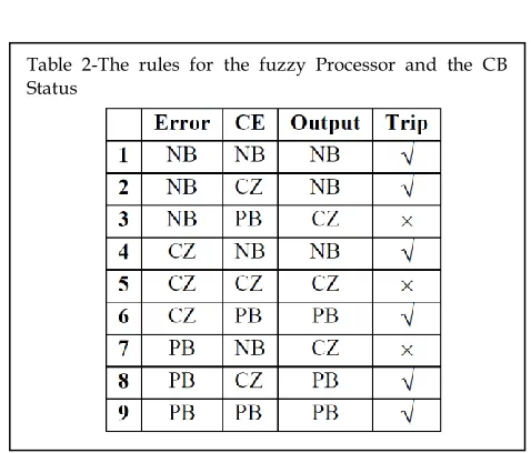
The Fuzzy logic processor in Simulink® is an extension of fuzzy logic toolbox in Matlab®. Using the fuzzy logic toolbox the logic was developed so that the processor will process change in error and error and give an output based on that. In the processor there are two inputs and one output function. The membership functions are all Gaussian MF. The Rule of the fuzzy processor is given below at Table 1 and Table 2.
5.2.4 Simulating Permanent Phase-Ground fault:
If the fault is permanent then the system should isolate the protection zone from the faulty zone. In this part a permanent line to ground fault was simulated using a fault breaker and a timer. The timer is set in such a way that it triggers a line-ground fault at 0.042sec (42ms). Also the logic for the transient fault detection was set in such a way that after the fault it will wait for the next 1.5cycle to see the fault is transient or permanent. In this simulation two circuit breakers were used. First one is for simulating the fault itself (zero voltage) and the second one is to simulate the actual circuit breaker. So the timing of the simulation will be not theoretical. The reason for this is because the circuit breaker in the Simulink® is modeled after the actual circuit breaker and it wasn’t meant to be used as a fault simulating device.
Fig.4 Fuzzy based over current relay protection system
So after the fault at 42ms the CB is closed at 70ms which is after 28ms. This 28ms delay was programmed to see that, in that 28ms if the fault clears or not. Because if the fault is still there, the transient fault logic give a signal to the CB to trip.
5.3.2 Simulating a Transient fault:
In the power system if there is a loose connection the system might be disconnected for just few milliseconds. In cause of fault that does not sustain for more than few milliseconds then the CBs should not trip. For the continuity of power system it is important to detect these transient faults. To detect the transient fault an extra logic circuit is used. In fig.7 the 1st signal is the actual sampled and estimated signal. At 42 ms the fault occurred and then at 62ms the fault is cleared automatically which is a transient fault, for a very small duration. The 2nd and 3rd signals are Error of estimation (E) and Change of error signals (CE). The Fuzzy processor processes 2nd and 3rd signal and gives an output signal which is the 4th signal in the Fig.7. It can be seen that at the time of fault the fuzzy processor gives more than 0.5 in its output. Which shows that a fault has occurred and it start to look for a fault clearing signal which is given by the fuzzy processor, processing the initial estimation error from the recovery voltage. The logic circuit sense the transient fault and gives signal so that the CB does not trip.
6
CONCLUSION
In this study, experimental results of a novel protective relay based on fuzzy logic and value estimation were presented. It can also detect Transient fault and handle it successfully. In addition to the theoretical aspect of fuzzy logic, mathematical definition of the value estimation, detection and measurement of faulty current, determination of its duration, decision mechanism and detailed system architecture were also introduced. Fuzzy inference is a process that makes a decision in parallel. Because of this property, there is no data loss during the process and so final fault detection will be far more precise than that of conventional relaying techniques. The proposed relay was applied to the prototype power system and finds satisfactory results the proposed relay was developed by using conventional protective relay characteristics by adding some abilities such as distinguishing whether the fault was transient or permanent, improved human safety and system reliability and determining correct action.
A
CKNOWLEDGMENTThe authors wish to thank Muhammad Jakaria Rahimi, Assistant Professor, Department of Electrical and Electronic Engineering (EEE), Ahsanullah University of Science and Technology (AUST).
Fig.7 A Transient fault simulation; Signal 1: Sampled and Estimated signal, Signal 2: Error signal, Signal 3: change of error, Signal 4: Output of the fuzzy processer, Signal 5: Input for the CB
R
EFERENCES[1] IEEE Standard Dictionary of Electrical and Electronics Terms, IEEE, Wiley Interscience, 1972
[2] D’Amore, D. & Ferrero, A. (1989). A Simplified Algorithm for Digital Distance Protection Based on Fourier Techniques. IEEE Trans. on Power Delivery, 4, 157-164.
[3] Girgis, A. A. & Makram, E. B. (1988). Applied of Adaptive Kalman Filtering in Fault Classification, Distance Protection, and Fault Location Using Microprocessors. IEEE Trans. On Power Systems, 3, 301- 309.
[4] J. Singh, M. S. Sachdev, R. J. Fleming, E. Krause, “Digital IDTM Overcurrent Relays,” Proceedings of IEE 1980 DPSP
Conference, IEE Publication No. 185, pp. 84-87.
[5] E. O. Schweitzer and A. Aliaga, “Digital Programmable Time-Parameter Relay Offers Versatility and Accuracy,” IEEE Transactions on Power Apparatus and Systems, Vol. PAS-89, No. 1, pp. 152-157, Jan./Feb. 1980.
[6] Z. Peng, M. S. Li, C. Y. Wu, T. C. Cheng, and T. S. Ning, “A dynamic State Space Model of a Mho Distance Relay,” IEEE Transactions on Power Apparatus and Systems, Vol. PAS-104, No. 12, December 1985.
[7] Waldemar Rebizant, Daniel Bejmert, Janusz Szafran, “Fuzzy logic based overcurrent protection for MV networks”
Proceedings of the Modern Electric Power System Conference 15th PSCC, Liege, 22-26 August 2005