Solar Tracking System using Delta PLC
L. Umasankar N.S Elanthiraiyan
Department of Electrical & Electronics Engineering AE/EM CHP divisions RMK College of Engineering & Technology, Anna University North Chennai Thermal Power Plant
Chennai-25
N. Hariharan Dr. N. Kalaiarasi
Department of Electrical & Electronics Engineering Department of Electrical & Electronics Engineering RMK College of Engineering & Technology, Anna University RMK College of Engineering & Technology, Anna University
Chennai-25 Chennai-25
Abstract
The main objective of this project is to achieve the maximum power output from the solar panel or the photovoltaic panel. In general, the Sun’s Path is from East to West but the Sun’s position changes from season to season. Keeping this in mind we have designed a system which rotates in three dimensions so as to trap maximum amount of photons from the Sun rays. The photovoltaic panel converts the solar energy (photons) into Electrical energy. By doing this the output efficiency of the system is increased compared to the efficiency of single axis tracking system. The overall project is controlled by PLC (Programmable Logic Controller) and the LDR values, rotation of panels is monitored through the Wonder Ware In touch Software installed in Personal Computer.
Keywords: Solar tracking, Delta PLC, LDR
________________________________________________________________________________________________________
I. INTRODUCTION
To prevent the effects related to global warming, which is caused by the greenhouse gases emission, the renewable energy has been the best substitution strategy. About 40 minutes of solar radiation on the earth would provide enough power to meet the energy demands of all human beings for approximately one year. The generation capability of PV panel follows the intensity of the sunlight.
At present a lot of solar panel arrays are basically been fixed and cannot make use of solar energy resources, so power generation efficiency is lower. If vertical direction can always be kept between solar panels and light, in order to maximise the solar energy received, which can take full advantage of abundant solar energy resources.
The position of the sun with respect to any location of the earth changes in a cyclic track during the course of a calendar year. Tracking the position of the sun in order to expose a PV panel to maximum radiation at any given time and any location is the aim of an automatic solar tracking system. A prototype of the automatic multi-axis solar tracking system with a new designed position tracker mechanism and wireless supervisory and control system was designed and implemented in this paper. The sun-position tracker mechanism was made of the PLC, DC motors, stepper motor, LDR-sensors, and power relays. With this setup we increase the efficiency of the tracking system,
II. SYSTEM DESCRIPTION
Solar Tracking System using Delta PLC
(IJSTE/ Volume 2 / Issue 11 / 081)
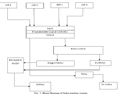
Fig. 1: Block Diagram of Solar tracking system
Already the ladder logic is installed in the PLC. In order to activate the PLC, 5V DC supply is given. The LDR placed in solar panel gives the input values to PLC. The PLC processes the input values based on ladder logic programmed in it. The output from the PLC is given to the stepper motor and DC motor. Meanwhile, the DC motor and stepper motor is excited by 12V DC supply. The PLC works with respect to the ladder logic sequence. It will send the signal through output terminal and rotates the solar panel with respect to the LDR’s value. LDR values will decide in which direction the solar panel has to rotate.
Fig. 2: Light Dependent Resistor
Thus we store the energy received in a battery and then use during demand arises.
III. SOLAR TRACKER SYSTEMATIZATION
Fig. 3: Working of solar tracking system
When there is decrease in intensity of light, this system automatically changes its direction to get the maximum intensity of light. Here we are using two sensors in two different directions to sense the direction of the maximum intensity of light. The difference between the outputs of the sensors is given to the PLC unit. Here we are using the PLC for tracking and generating power from sunlight. It will process the input voltage, which is from the comparison circuit and control the direction in which the motor has to be rotated so that it receives the maximum intensity of light from the sun. The power generated from this process is then stored in the lead acid battery and is used to charge an emergency light and is made to glow during night.
Trackers classification by the tracking principle
There are many approaches in PV panel orientation towards the Sun position. They can be divided into three types.
Open-loop trackers determine the position of the Sunfor a specific location and time by using special mathematical formulas [13]. Such systems are insensitive to the side illumination and problems with determination the exact position of the Sun when it's cloudy. However, these trackers must be periodically calibrated. In addition, it is necessary to use expensive actuators with position feedback.
Closed-loop trackers provide orientation of the panel due to a feedback signal from the sensor. The advantage of this system is the ability to use virtually any actuators, insensitivity to placement errors and ability to function even in transportable units (no need for the precise placement by the cardinal directions after transportation).
Hybrid trackers have the Sun position sensor, which is used to precisely adjust orientation in some region near the calculated position. During sunny weather system can be controlled by the signals from the sensors, while in cloudy sky the orientation that are calculated by program can be used. Hybrid systems can provide the highest precision in orientation. They are widely used in concentrator PV which requires lowest orientation tolerance.
IV. SYSTEM REALIZATION AND EXPERIMENTATION
Solar Tracking System using Delta PLC
(IJSTE/ Volume 2 / Issue 11 / 081)
Programmable Logic Controller (PLC) Unit
Tracking controller is used to be a programmable logic controller (PLC), it is a system core of the tracking system of the PV panel, at the same time, is the focus of research system. Specially, there are the advantages of the centralized control through the PLC fieldbus to the tracking system of the PV batteries arrays of the series-parallel connection of the synchronization network. After researching and optimizing the design, the tracking controller has the advantages of the high tracking accuracy, wide operating range and it returns automatically through comparing with the differential voltage analog variable.
The devices were ensured work reliably after using the dual limit control structure, that is, control signals limit and motor drive limit
Sensors Detecting and Signal Processing Unit
With the different observation location and the observation time, sunlight direction is different, therefore, sun’s position has to be tested and located first if sunlight needs be tracked. We use Light dependent resistors (LDR) to track the sun effectively. The analog signals from LDR’s are fed into PLC and the processing unit converts the analog signal into digital signal. Depending upon the speed of the processors the accuracy is maintained. Tracking is done with some time delay in between the position changes.
The advantages of relative method of sunlight strength to photo resistance lied in accurate control and circuit design to achieve easily.
System Power Module
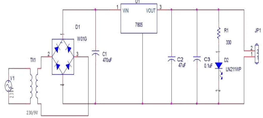
Power circuit uses the switching power design with characteristics of high efficiency, low loss. The chip L4960 is used to switch could provide a 5.1~40V output voltage and a 2.5A output current. Through adjusting resistance, which produced 12~24V DC voltage, 24V (DC) for PLC power, 44V (DC) is output directly from the bridge rectifier in order to provide to DC motor. If the inverter for the photovoltaic systems tracking system was used, 220V (AC) could be taken directly from the photovoltaic inverter power.
Fig. 4: Power Supply Unit
PLC control and monitoring programs
The PLC control statements were the important constituent of the entire solar panel tracking system, and the software programming was done using ladder logic coding and was written in CPU module of the PLC and then processed and executed.
The PLC was monitored data in real-time, was modified edited on-line, and so on, and the programs were transferred to the PLC and the data were read from the PLC conveniently.
PLC completed the following major tasks:
1) PLC controls the movement in tracking system, and control logic.
Fig. 5: Flow Diagram of tracking system
Solar Tracking System using Delta PLC
(IJSTE/ Volume 2 / Issue 11 / 081)
V. HARDWARE SETUP
The below figure shows the hardware setup of the solar tracking system and the components used for tracking
Thus the stepper motor is used to rotate the panel in East or West direction whereas the DC motor is used to rotate the panel in three dimensional axis. The voltage regulator circuit will regulate the voltage and the received solar energy gets stored in the battery.
VI. CONCLUSION
ACKNOWLEDGEMENT
We are very much thankful to Mr. N.S Elanthiraiyan, AE/EM CHP division, North Chennai Thermal Power Plant, Chennai-120, for his extended support and help throughout this project. We are indeed thankful to our college and our staffs for providing us all the facility to complete our project successfully.
REFERENCES
[1] T. Esram and P. L. Chapman, “Comparison of Photovoltaic Array Maximum Power Point Tracking Techniques,” IEEE Transactions on Energy Conversion, vol. 22, no. 2, pp. 439–449, Jun. 2007.
[2] C.Roncero-Clemente, O. Husev, V. Minambres-Marcos, E. Romero-Cadaval, S. Stepenko and D. Vinnikov, “Tracking of MPP for three-level neutral-point-clamped QZ-source off-grid inverter in solar applications,” Journal of Microelectronics, Electronic Components and Materials, vol. 43, no. 4, pp. 212 – 221, 2013.
[3] O.Veligorskyi and Y.Vagapov, “Improvement of perturb and observe MPPT method for photovoltaic systems: case of study,” International Journal of Renewable Energy Technology, vol. 4, no. 2, pp. 141–156, 2013.
[4] E. Lorenzo, M. Perez, A. Ezpeleta, and J. Acedo, “Design of tracking photovoltaic systems with a single vertical axis,” Progress in Photovoltaics Research and Applications, vol. 10, no. 8, pp. 533–543, Dec. 2002.
[5] K. Chong and C. Wong, “General formula for on-axis sun-tracking system and its application in improving tracking accuracy of solar collector,” Solar Energy, vol. 83, no. 3, pp. 298–305, March 2009.
[6] İ. Sefa, M. Demirtas, and İ. Çolak, “Application of one-axis Sun tracking system,” Energy Conversation and Management, vol. 50, no. 11, pp. 2709–2718, Nov. 2009.
[7] A. Şenpinar and M. Cebeci, “Evaluation of power output for fixed and two-axis tracking PV-arrays,” Applied Energy, vol. 92, pp. 677–685, Apr. 2012. [8] M. Alata, M. a. Al-Nimr, and Y. Qaroush, “Developing a Multipurpose Sun tracking system using fuzzy control,” Energy Conversation and Management,
vol. 46, no. 7–8, pp. 1229– 1245, May 2005.
[9] R. Grena, “Five new algorithms for the computation of Sun Position from 2010 to 2110,” Solar Energy, vol. 86, no. 5, pp. 1323–1337, May 2012. [10] H. Mousazadeh, A. Keyhani, A. Javadi, H. Mobli, K. Abrinia, and A. Sharifi, “A review of principle and Sun-tracking methods for maximizing solar systems