Vol. 08, Issue 12 (December. 2018), ||V (I) || PP 01-08
Numerical Analysis for Rate of Heat Transfer and Optimal
Dimensions of a Circular Fin with Hyperbolic Profiles
S.Ravi Kumar
Professor Dept of Mechanical Engineering, Hyderabad Institute of Technology and Management.
Abstract: The present article deals a solution to the problem of circular fin with hyperbolic profile numerically. A fin with this type of geometry resembles the optimal circular fin of convex parabolic profile, which delivers the maximum heat transfer for a given volume of material. The circular fin of hyperbolic profile is governed by a two-term differential equation of second order with one variable coefficient which, via a transformation can be converted into a Bessel equation. Unlike adopting the conventional Bessel’s functions, the present paper discusses an easy alternative to solve the problem by using finite difference techniques for a preliminary solution which is further refined using numerical programming in C. In this method as the interval size is decreased, the solution to the problem approaches towards that of exact method. Finally a test problem is discussed to check the validity of present formulation. Temperature distribution and heat transfer rates are compared with earlier exact methods and experimental results on graphs which confirm the correctness of present formulation. Another important outcome of this article is, running the programme for various values of input parameters an optimum dimension of the fin for maximum heat transfer can be decided.
--- --- Date of Submission: 19-11-2018 Date of acceptance: 04-12-2018 --- ---
Nomenclature
C Normalized radii ratio=
2 1
r
r
h Convective coefficient
k
m
w
2
I
Modified Bessel function of first kind and order vk Constant thermal conductivity
mK
W
L Length of fin (m)
2
M
Thermo geometric parameter or modified Biot number (Bi*) =
k
r
t
hr
1 1
3 2
Q Dimensionless heat transfer rate
conv
Q
Convective heat transfer from the surface of fin (W)R Dimensionless radii ratio =
1
r
r
1
r
Inner radius (m)2
r
Outer radius (m)1
t
Inner thickness (m)2
t
Outer thickness (m)T Temperature on surface of fin at a distance ‘r’ from fin base (°C)
b
T
Base temperature (°C)a
I.
INTRODUCTION
The problem of heat removal is a major issue in the modern industry. The reason for researching in the field is both to increase the performance of the target system and to reduce the damage that high temperature can cause. Fins or extended surfaces dissipate the unwanted heat from the surface which is very much essential for proper functioning of the component. Circular fins usually increase the heat transfer from primary metallic surfaces (e.g., tubes, cylinders and rods) to surrounding fluids. A common type of fin used in heat exchanger tubes is the circular fin of constant or tapered thickness. Typical applications of circular fins are found in air-cooled engines of motorcycles and automobiles, and in tubes of liquid–gas heat exchangers used in the refrigeration industry. Abdul Aziz [1] provided the optimum dimensions of fins and spines with different profiles. Murray [8] presented the effectiveness of annular fins with constant thickness and a symmetrical temperature distribution. Carrier and Anderson [2] discussed straight annular fins of constant cross sectional area and presented equations for fin efficiency. Their solutions were in the form of infinite series. Schmidt [9] discovered that the annular fin of convex parabolic profile dissipates the maximum amount of heat for a given volume of the material. This particular fin was appropriately named there after the optimum annular fin [10]. A draw back posed by the convex parabolic profile is its sharp tip which is very difficult to manufacture and maintain in the plant environment.
The importance of the circular fin of hyperbolic profile is that it closely resembles the optimal fin of convex parabolic profile discovered by Schmidt [9]. The analysis of a hyperbolic profiled fin with constant thermal conductivity and uniform heat transfer coefficient is done in Schneider [10] using Bessel’s function.
The main objective of present paper is to describe a method to calculate temperature distribution and heat transfer from a hyperbolic profiled fin using an approximate method of finite difference technique as a preliminary solution and refining it using a C programme. The method is an easy and versatile alternative for calculations to Bessel equation which is very much complicated, time consuming and tedious.
II.
FORMULATION
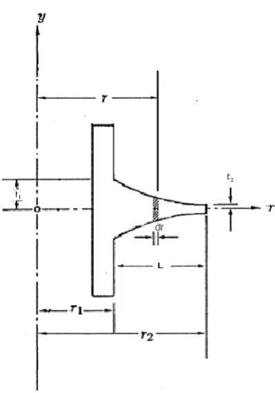
A circular fin with hyperbolic profile is considered for analysis. The configuration of fin is shown in fig
1(a). Fin inner radius and inner semi thickness are
r
1 ,t
1. Similarly outer radius and outer semi thickness arer
2and
t
2Fig1 (a) Configuration of Circular Fin with Hyperbolic profile.
Fig 1 (b) Heat balance on an element of fin
When the cross sectional area for heat transfer in a fin is variable, the conduction equation involves a linear second order differential equation with variable coefficients. With the assumption of constant thermal conductivity (k), uniform heat transfer coefficient (h) on entire
surface, constant base and environment temperatures the heat balance equation is written for an elementary area as shown in fig 1(b).
)
2
)(
(
2 2
r
T
T
hdr
dr
dr
T
d
k
A
dr
dT
k
A
dr
dT
k
A
r
r
r
(1)On simplification equation (1) reduces to
1 1 2
2
)
(
r
kt
T
T
hr
dr
T
d
And non dimensionalising the above equation we get
0
2 2 2
R
M
dR
d
(2)
Where
M
2is the thermo geometric property defined byk
r
t
hr
1 1
3 2
(modified Biot number, Bi*)
is a dimensionless temperaturea b
a
T
T
T
T
and R is
2
r
r
The boundary conditions to which the fin is subjected is At,
R
c
1
(3)(Known temperature at fin base)
And when
R
1
0
,
dR
d
(4)
(Negligible heat loss at fin tip)
Once the dimensionless temperature distribution
R
(
)
is obtained by this solution method, the heat transfer Q, from an annular fin to a fluid can be computed in two ways: by utilizing the derivative of Q(R) at the fin base asc R
dR
d
Q
2
(5)Or by the method of integration on the entire length of the fin from R=c to 1 as
212
c
RdR
M
Q
(6)Therefore the efficiency of the fin can be written as
)
1
(
2
2 2C
M
dR
d
c R
(7) Or
)
1
(
2
2 1C
RdR
C
(8)III.
EXACT ANALYTICAL SOLUTION.
Exact analytical solution as given by P.J.Schneider [10] was obtained by means of a variable transformation. He has shown that equation (2) can be solved using the appropriate boundary conditions and Bessel’s equations, solution to differential equation was written in the form of
M
I
Mc
I
M
I
Mc
I
M
I
MR
I
M
I
MR
I
c
R
R
3
2
3
2
3
2
3
2
3
2
3
2
3
2
3
2
3 / 2 2 / 3 3 / 1 3 / 2 2 / 3 3 / 1 3 / 2 2 / 3 3 / 1 3 / 2 2 / 3 3 / 1
(9)Inserting equation (9) in to the fin efficiency expressions of (7) and (8) give the exact equation to calculate the fin efficiency Ref[10].The structure of fin efficiency equation is more complicated than equation(9).
IV.
PRELIMINARY SOLUTION USING FINITE DIFFERENCE TECHNIQUE.
The length of fin is divided into I equal intervals by that the interval size will be
R
(
1
C
)
/
I
and number of nodes will be (I+1)Now the second order derivative will be
2 1 1 2 2
)
(
2
R
dR
d
i i ii
(10)Here
(
R
)
2 is the truncation error.0
]
)
(
2
[
2 2 11
i i
i
M
R
R
(11)Equation (11) is an important equation generator. By the known parameters of
M
2,(
R
)
2 and the two end conditions of the fin a set of equations can be generated.V.
RESULTS AND DISCUSSIONS
To check validity of the formulation, it is compared with the exact solutions using a numerical problem. Considering a pure aluminum circular fin with hyperbolic profile having thermo geometric properties
of
M
2 as 8.531 and C=1/4. Heat rejected to atmosphere with base temperature of fin asT
b and the atmospheric temperature asT
a.Here the fin is divided into three equal intervals of size
R
1
\
4
From the equation generator (11) the three nodal temperatures can be found out by solving the three set of equations generated.
For i=1
2
2
.
266
1
1
0
(12)i=2
3
2
.
4
2
1
0
(13)i=3
2
.
533
3
2
2
0
(14)On solving the above set of equations we get
1=0.608,
2
0.3775, and
3
0.298.The above values are used to calculate the temperature gradient at the fin base.
'
at the fin base isR
01
= -2.091.
(This value of temperature gradient is used as an initial guess in the C programme.) The equation (2) can be written in the form of the simultaneous equations.
R
M
dR
dZ
2And
dR
d
Z
(15)0.3 0.4 0.5 0.6 0.7 0.8 0.9 1.0
0.0 0.2 0.4 0.6 0.8 1.0
1-Present analysis 2-From Ref 2
2 1
Dimensionless Space vaiable
Dimensional T
emperature
Range kutta method is used to get the solution for the simultaneous equations (mathematical procedure is omitted). And the C programme is complied to get the nodal values of dimensionless temperatures and temperature gradients for the solution.
This numerical method is preliminarily validated before applying to other test problems. A direct comparison of surface temperature between the present analysis and the exact equation given by Schneider [10] results a good agreement as seen in fig2.
As the normalized radii ratio approaches towards the limiting value 1, the surface profile becomes flat. Analysis for a flat profile of an annular fin is validated with the experimental data available in Ref [3] for fin lengths of L=0.15, 0.1 and 0.05mtrs.This is shown in Fig.3. The analysis is in close agreement with the experimental data. Fig 4 shows the temperature distribution on surface of a fin with C=0.25 from inner radius to outer radius for four different values of modified Boit numbers (Bi*). Fig 4 can be used to find the tip and intermediate temperatures on the fin
For a given fin volume as the normalized radii ratio(C) decreases, the cross sectional area for heat conduction decreases. This decrease in C yields in two effects. Because of increase in convective area the heat transfer rate increases and the heat conduction from the fin base decreases. The latter plays a dominant role for normalized radii ratio lesser than certain values as shown in fig 5 which is plotted for a test problem with Bi*=10,15&20 to get the dimensionless heat transfer rate for four different values of C. This can be used to optimize the fin dimensions.
The modified Biot number mainly depends on geometric constants since in this analysis other terms of the group are assumed to be constant for a particular material of the fin. Fig 6 which is drawn for the different values of C can be used to find the optimum value of Bi* and thus the optimum dimensions of the fin can be decided for maximum heat transfer rate. It is obvious from the figure that as the normalized radii ratio is increasing the maximum value of convective heat transfer rate is decreasing and shifting towards the higher values of modified Boit number.
0 20 40 60 80 100 120
0 5 10 15 20 25 30
3
2
1
Excess Temperature(Tb-Ta)
Expermental [3] Present anlysis L=0.05 1 L=0.05
L=0.1 2 L=0.1 L=0.15 3 L=0.15
Conv
ectiv
e Heat tran
sfer (W
)
0.3 0.4 0.5 0.6 0.7 0.8 0.9 1.0 0.0
0.1 0.2 0.3 0.4 0.5 0.6 0.7 0.8 0.9 1.0
Bi*=10 Bi*=12
Bi*=15 Bi*=20
Dimensionless T
emperature,
Dimensionless radii ratio, R
Fig: 4 Variation of Temperature distributions on surface at different modified Biot number
2 3 4 5 6 7 8 9 10 11 12 13 14 15 16 0
3 5 8 10 13 15 18 20 23 25 28 30
C=0.5 C=0.35
C=0.25
Conv
ectiv
e heat
transfer, Q
C
on
v
Modified Biot number, Bi*
2 3 4 5 6 7 8 9 10 11 12 13 14 15 16 0
3 5 8 10 13 15 18 20 23 25 28 30
C=0.5 C=0.35
C=0.25
Conv
ectiv
e heat
transfer, Q
C
on
v
Modified Biot number, Bi*
Fig: 6 Heat transfer rate as a function of modified Biot number at different normalized radii ratio
VI.
CONCLUSIONS
Laborious calculations using venerable Bessel’s functions is avoided by adopting a new method of finite difference techniques to the basic two-term differential equation of second order with one variable coefficient as a preliminary solution to the circular fin with hyperbolic profile. The validity of present formulation is checked by comparing the temperature distribution on the fin surface with that of exact methods available in Ref [10]. The convective heat transfer rates for various values of difference between base and atmospheric temperatures are compared with the experimental data of Ref [3] and found to be in good agreement. For Runge Kutta method of solution of simultaneous equations a numerical programme in ‘C’ is complied which is used to calculate the optimum value of thermo geometric property for a fixed value of normalized radii ratio and thus used to find dimensions of the fin for maximum heat transfer rate. The analytical expressions for this numerical method are compact, permitting the study to a wide range of combinations of two controlling parameters namely normalized radii ratio ( C) and modified Biot number (Bi*).This method can be extended with ease to a general class of annular fins with flat profile which can be optimized for maximum heat transfer rate.
REFERENCES
[1]. Abdul Aziz, Optimum dimensions of extended surfaces operating in a convective environment, Appl. Mech. Rev. Vol 45 (5), pp155–173, 1992.
[2]. W.H. Carrier, S.W. Anderson, The resistances to heat flow through finned tubing, Heat Piping Air Cond.Vol 10 pp304–320, 1944.
[3]. A.Guvenc, H.Yuncu, An experimental investigations on performance of fins in a vertical base in free convection heat transfer, Heat and mass transfer, pp409-416,2001,
[4]. M.K.Jain and S.K Iyengar, A text book on Numerical methods for scientific and engineering computations, New age international publishers, 2003.
[5]. A.D. Kraus J.R. Welty, Extended surface heat transfer, Wiley, New York, 2000. [6]. J. H. Lienhard, A Heat Transfer Textbook .Prentice-Hall, Englewood Cliffs, NJ, 1981. [7]. A. F. Mills, Heat Transfer .Irwin, Boston, MA, 1992.
[8]. W.M. Murray, Heat dissipation through an annular disk or fin of uniform thickness, J. Appl. Mech. Trans. ASME,pp60 -78,1938.
[9]. E. Schmidt, Linear heat transfer from a fin. International journal of Engineering science. Vol 70, pp. 885-889, 1956.
![Fig 2 Comparison of present formulation with P. J. Schneider, Ref [10]](https://thumb-us.123doks.com/thumbv2/123dok_us/7805533.1661440/5.595.74.453.262.701/fig-comparison-present-formulation-p-j-schneider-ref.webp)
