RESEARCH
Comparisons Between Pull-Out Behaviour
of Various Hooked-End Fibres in Normal–High
Strength Concretes
Sadoon Abdallah
*and David W. A. Rees
Abstract
In this paper an elastic–plastic response has been developed to predict the pull-out behaviour of various hooked end fibres embedded in normal–high strength concretes. An elastic–plastic moment expression has been proposed to represent the partially plastic hinge formed during pull-out. The proposed formula has been incorporated into a fric-tional pulley force analysis in order to predict the applied loading at each stage of pull-out. This prediction accounts for the variation of geometrical and tensile properties of the fibres as well as concrete strength. The proposed model is validated against experimental pull-out results of various hooked end fibres.
Keywords: pull-out behaviour, normal-high strength concrete, hooked end fibres, an elastic–plastic response, frictional pulley analysis
© The Author(s) 2019. This article is distributed under the terms of the Creative Commons Attribution 4.0 International License (http://creat iveco mmons .org/licen ses/by/4.0/), which permits unrestricted use, distribution, and reproduction in any medium, provided you give appropriate credit to the original author(s) and the source, provide a link to the Creative Commons license, and indicate if changes were made.
1 Introduction
The use of steel fibre reinforced concrete (SFRC) as an alternative to traditional rebar or mesh reinforcement has highly influenced the design of modern structures. Plain concrete is characterised by its brittle behaviour in tension (Zendaoui et al. 2016; Abdallah et al. 2018a, b). Steel fibres incorporated are dispersed within the concrete in order to improve its ductility, tensile behav-iour and impact resistance (Tadepalli et al. 2013; Adjrad et al. 2016; Abdallah et al. 2018a, b). Of these the great-est advantage of including steel fibres in the concrete is to impart ductility to an otherwise brittle material. Steel fibres enable the concrete to continue carry load after cracking, the so-called post-cracking behaviour (Abdal-lah et al. 2016b; El-Mal et al. 2015). A further benefit of the addition of steel fibres is to impart extremely good crack resistance. High strength steel fibres when distrib-uted homogeneously throughout the concrete matrix provide very effective crack control as there will always
be a fibre in the neighbourhood of a micro-crack, pre-venting the crack from growing.
The post-cracking behaviour of SFRC is closely related to the bond characteristics between the fibre and the matrix (Won et al. 2013; Abdallah et al. 2017c, d). The efficiency of fibres in bridging cracks depends upon the bond mechanisms associated with the pull-out behaviour (Islam and Alam 2013; Li and Liu 2016; Abdallah et al. 2017b). Tensile stress in the concrete matrix is trans-ferred to the fibre through a characteristic durable bond at their interface. In order to increase the load-carrying capacity of SFRC, steel fibres with a variety of different shape and size are introduced. Hooked ends, enlarged ends, spiral, twisted and crimped are among the different designs available. Of these, Dramix hooked end fibres of 4D (double bend) and 5D (triple bend) geometries were developed specifically to increase the crack-bridging ability of SFRC. The high mechanical anchorage effect of these fibres was demonstrated in a number of prior studies showing that their strong bonding to the matrix resulted in a high resistance to pull-out (Abdallah and Fan 2017). Fibre with more a complex pre-deformed geometry place a higher complexity on the analysis of its pull-out response (Abdallah et al. 2017c, d). As the number of hook bends increases, both the maximum
Open Access
*Correspondence: [email protected]
College of Engineering, Design and Physical Sciences, Brunel University London, Uxbridge, London UB8 3PH, UK
pull-out load and pull-out work increase significantly. Numerous experimental investigations on the pull-out behaviour of pre-deformed fibres have been carried out to clarify the influence of fibre geometry on the bond-slip response (Isla et al. 2015; Tuyan and Yazici 2012; Soetens et al. 2013b; Robins et al. 2002). It has been shown from the pull-out test that a hooked end fibre is an effective method for improving the bond-slip resistance (Abdallah et al. 2017a).
Over the past four decades several analytical models have been proposed to predict the pull-out behaviour of steel fibres with various shapes (Lee et al. 2010; Nammur and Naaman 1989; Soetens et al. 2013a; Georgiadi-Stefa-nidi et al. 2010; Naaman et al. 1991a, b; Deng et al. 2018). The first attempts to predict the pull-out behaviour of hooked end fibres were advanced by (Chanvillard 1999) and (Alwan et al. 1999). Chanvillard model’s is based on the concept of virtual work dividing the hook into dis-tinct straight and curved parts. Alwan et al. (1999) used the frictional pulley analogue to determine the anchor-ing forces provided by the fibre hook. The latter’s con-tribution is considered a function of the work needed to straighten the fibre during pull-out. Sujivorakul et al. (2000) extended the straight fibre pull-out analysis devel-oped by Naaman et al. (1991a) by adding a non-linear spring to the end of the fibre to simulate the mechanical anchorage contribution.
In recent work, (Laranjeira et al. 2010; Lee et al. 2010; Ghoddousi et al. 2010) proposed alternatives to the pulley model of Alwan et al. (1999). Zīle et al. (2013) developed an analytical model to simulate the mechani-cal contribution from fibre geometry to the pull-out response of crimped and hooked-end steel fibres. Their model is based both on the amount of plastic work required to straighten the fibre during pull-out and fric-tional resistance in the curved ducts. Won et al. (2015) extended this to the work required in straightening arch-type steel fibres.
The mechanics as explained in these theories involves a large number of parameters which are mostly restricted to a set of experimental boundary conditions and material properties. The rising applications of 4D and 5D hooked end fibres in modern structural applications have created the need to simplify theoretical analyses. For example, a semi-empirical pull-out analysis of these fibres was pro-posed by the authors to match observed behaviour sat-isfactorily (Abdallah et al. 2016a). This model adopted Alwan’s frictional pulley (Alwan et al. 1999) to account for variations in mechanical and geometrical properties of the fibres as well as the matrix strength. Previously the authors (Abdallah et al. 2016a) examined fibre-matrix conditions for a pull-out force where a full straighten-ing of the fibre was observed. This paper investigates the
conditions when the hook is not fully straightened during the pull-out as has been often observed. The elastic–plas-tic moment expression was advanced to represent the actual the plastic penetrations involved in the unbend-ing required. Here again when taken with the frictional pulley concept (Abdallah et al. 2016a) this paper shows how plasticity explains the pull-out behaviour of 3D, 4D and 5D fibres embedded in a specific concrete matrix. It is shown how this approach is applied to experimen-tal results for each hooked end fibre and three concrete matrices in normal-high strength range.
2 Experimental Program 2.1 Materials and Specimen
Three types of commercially available Dramix hooked end steel fibres, namely: 3DH (single bend), 4DH (dou-ble bend) and 5DH (triple bend) fibres were used in this study. These fibres have exactly the same length (60 mm), diameter (0.90 mm) and aspect ratio (lf/df= 65) but differ
in their hook geometry and tensile strength. The meas-ured geometrical and mechanical properties of these fibres (stacked) are depicted in Fig. 1 and detailed in Table 1. The average stress–strain curves of each fibre is shown in Fig. 2. To investigate the mechanical anchoring effect provided by each fibre hook, straight fibres (3DS, 4DS and 5DS) were obtained from the same hooked end fibres (3DH, 4DH and 5DH) by removing their hook ends.
Pull-out specimens were produced in three differ-ent concrete strengths, namely normal (NSC), medium (MSC) and high (HSC). Table 2 summarizes the mate-rials used and mix proportions for all mixtures. Cubic specimens with a side dimension of 100 mm were used for single pull-out tests. Each cube contained three fibres embedded carefully to a depth of a half fibre length i.e. 30 mm. For each mix, five cubic specimens were also prepared for compressive strength tests. During casting, the dry materials (cement, silica fume, sand and crushed granite) were firstly mixed for approximately 1 min before water and superplasticizer (for the HSC) were added. This was then mixed for roughly 11 min. After casting and vibrating, the specimens were covered with a plastic sheet to avoid moisture loss and left for 24 h at room temperature. After that, they were demoulded and left to cure for a further 28 days in a conditioning cham-ber at 20 ± 2 °C and 96 ± 4% RH.
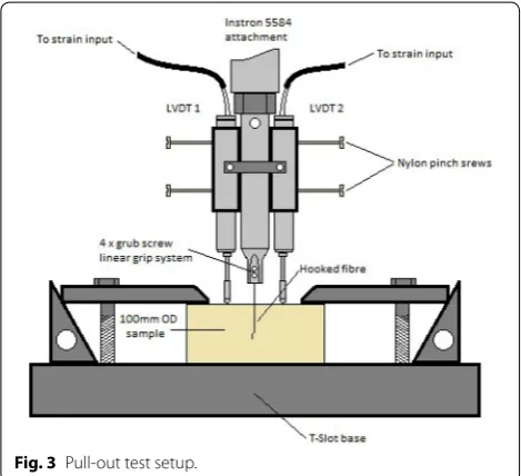
2.2 Test Setup
The body of the gripping system was machined in a lathe using mild steel and had a tapered end to allow the inser-tion of four M4 grub screws (Fig. 3). These were then tightened around the steel fibre to an equal torque for an even distribution of gripping pressure to minimise the deformation of the fibre ends and avoid breakage at the tip. Two linear variable differential transformer (LVDT)
transducers were used to measure the distance travelled by the steel fibre relative to the concrete face during test-ing (i.e. the pull-out distance). They were held in place using aluminium sleeves on either side of the main grip body (Fig. 3). The LVDT probes had ball bearings at their tips for accuracy in measurements taken from the top datum face. The sample was secured to the Instron base using clamps with riser blocks and M16 studs. The base rested on a round brass disc to retain flatness under test at a displacement rate of 10 µm/s.
2.3 Experimental Results
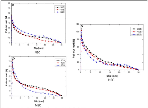
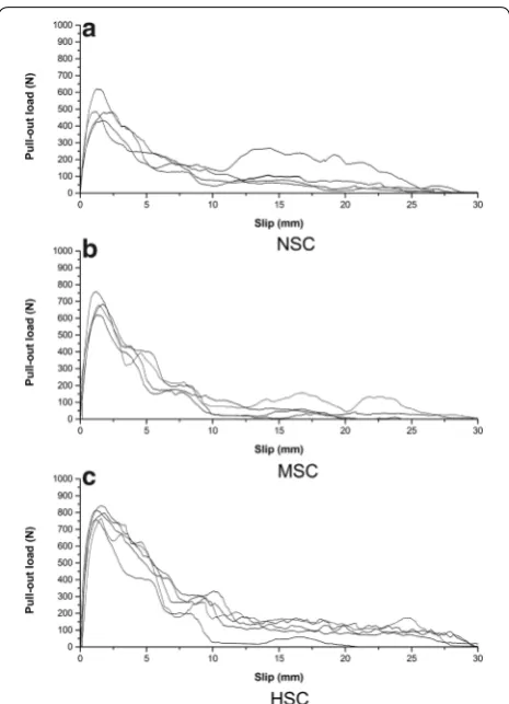
The average pull-out-slip curves of (3DS, 4DS and 5DS) straight fibres pulled-out from a NSC, MSC and HSC is shown in Fig. 4a–c. These show that the pull-out behav-iour of all straight behavbehav-iour is characterized by a rapid increase up to the peak load, followed by a sudden drop in the pull-out load, indicating full debonding of fibre/ matrix interface. After that, the pull-out behaviour is con-trolled entirely by dynamic frictional resistance, where pull-out load gradually decreases with the increase in slip. For the same concrete grade, the maximum pull-out load (Pmax) of 3DS, 4DS and 5DS fibres was quite similar,
as expected. This is mainly due to the fact that straight
Fig. 1 Geometrical properties of hooked end steel fibres.
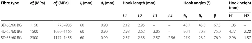
Table 1 The measured geometric and mechanical properties of hooked-end fibres.
a Ultimate strength. b Yield strength.
Fibre type σua (MPa) σyb (MPa) lf (mm) df (mm) Hook length (mm) Hook angles (°) Hook height
(mm)
L1 L2 L3 L4 θ1 θ2 β H1 H2
3D 65/60 BG 1150 775–985 60 0.90 2.12 2.95 – – 45.7 45.5 67.5 1.85 – 4D 65/60 BG 1500 1020–1165 60 0.90 2.98 2.62 3.05 – 30.1 30.8 75.0 4.37 2.20 5D 65/60 BG 2300 1177–1455 60 0.90 2.57 2.38 2.57 2.56 27.9 28.2 76.0 2.96 1.57
fibres (without hooks) have the same geometry, diam-eter, and embedded length and hence the pull-out behav-iour would remain almost the same. On the other hand, Fig. 4a–c show that Pmax for all straight fibres increases
significantly as the compressive strength of the concrete increase. Compared to the NSC, the percent increase in the Pmax in the case of MSC and HSC is 40% and 98%,
respectively as shown in Fig. 5.
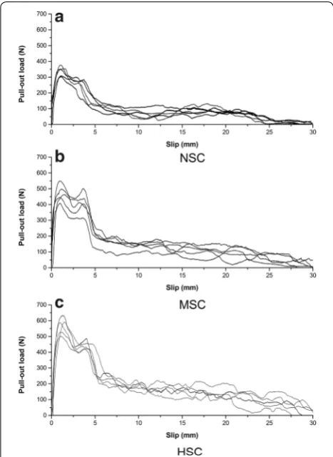
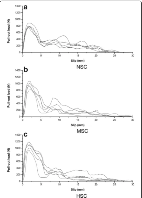
The experimental pull-out-slip curves of (3DH, 4DH and 5DH) hooked end fibres pulled-out from a NSC, MSC and HSC matrix are presented in Figs. 6, 7 and 8. It can be seen that the initial pull-out response of hooked end fibres is again governed by a combination of two dif-ferent mechanisms: debonding of the fibre–matrix inter-face and frictional slip of the fibre. However, in addition to these ‘straight-fibre’ mechanisms, mechanical interlock is introduced by the plastic deformation of the fibre hook. In contrast to a straight fibre, the mechanical anchorage contribution provided by a hooked end fibre increases the pull-out load after de-bonding significantly. It can be observed that Pmax for all hook end fibres increases with an increase in matrix strength. It is also evident that an
increase in number of hook bends increases Pmax
dramat-ically. The 5DH (triple bend) fibres showed considerably higher values of Pmax in all concrete matrices (Fig. 9). In
addition, the pull-out work of 5DH fibre was significantly higher than that of the 3DH (single bend) and 4DH fibres (double bend). The higher performance for 5DH fibre is due to the high energy needed to deform and straighten the hook bends. However, despite the increased energy consumed during the pull-out, the full straightening of 4DH and 5DH hook bends was not observed (Fig. 10). However, the straightening of the hook increases sig-nificantly as the matrix strength increases e.g. a hooked end fibre pulled-out from the HSC showed higher levels of hook straightening that those of the NSC and MSC (Fig. 10). This indicates consistently that concrete matrix with higher strength is needed to ensure the hook bends are almost completely straightened. The benefit of this feature of fibre reinforcement is worth evaluating in the following section.
3 Elastic–Plastic Moment Expression
An estimate of the spread of plasticity within the hook bends is a necessary requirement when predicting the force required to pull-out an embedded fibre from a con-crete matrix. What follows is based upon a wire bend of uniform curvature ‘equivalent’ to the various hook geom-etries i.e. 3D, 4DH and 5D fibres.
Consider a circular wire fibre section of radius rf sub-jected to a uniform hogging bending moment M as
shown in Fig. 11. A fully elastic moment ME refers to that stress distribution given in which the yield stress σy has been reached at the top and bottom positions for the sec-tion in tension and compression respectively.
The moment ME refers to a limiting condition at which the elastic theory of bending applies:
in which Ef is the fibre modulus, ρE is the fully
elas-tic curvature of the unstressed neutral axis (N.A) and I = ∫Ay2dA is the second moment of the section’s area (1)
ME
I =
Ef
ρE
= σy
rf Table 2 Mix design of mixtures.
Concrete type Mix proportions (kg/m3) W/B (
−) Compressive
strength
Cement (type) Fly ash Aggregates Sand Superplasticizer Water (MPa)
8–10 mm 0-mm
NSC 364 (32.5R) – 979 812 – 200 0.55 33
MSC 350 (52.5N) 107 660 1073 – 205 0.45 54 HSC 480 (52.5N) 45 850 886 6 210 0.40 72
about the x-axis. The following relationships apply from re-arranging Eq. (1) when I= πr
4
f
4 for the fibre’s circular section:
When M>ME plastic zones penetrate inwards from the top and bottom to depth h as shown in Fig. 12. The new beam curvature ρe (Fig. 11) applies to the inner region of elastic material with reduced second moment of area Ie . The elastic–plastic moment Mep is spilt with two contributions:
(2) ME =
EfI
ρE
= σyI
rf
(3)
ρE= EfI
ME = Efrf
σy
(4)
∴ME = πEfrf4
4ρE =
π σyrf3
4
(5)
Mep=Me+Mp
Fig. 4 Average pull-out-slip response of straight steel fibres. a NSC, b MSC and c HSC.
where the elastic contribution, Me applies bending the-ory to an elastic core. Given the small diameter of wire this core is assumed to be circular of radius rf −h with a simplified second moment of area Ie= π(rf−h)
4
4 . Here, Me and the elastic curvature ρe are given as:
The plastic contribution Mp assumes that σy is uni-formly distributed within each penetration area. For the strip area δA shown in the first diagram of Fig. 11, δMp becomes the couple produced from the opposing parallel forces σyδA separated by 2y:
(6) Me=
σyIe rf −h
= σy×π(rf −h) 4
4
rf −h = π σy
4 (rf −h)
3
ρe= Ef
rf −h
σy
=
Efrf
1− h rf
σy
δMp=2σyδAy=2σy
2(rf2−y2)1/2δy×y
where δA is the bracketed quantity. Integrating between the limits of y as:
The sum of Eqs. (6) and (7) provides the elastic–plastic moment required for plastic penetration of each zone to depth h :
When Eq. (8) is normalised with the fully elastic moment in Eq. (1) it becomes:
which is written in a convenient dimensionless form:
So enabling the following checks: when h rf =0 ,
Mep=ME , at full elasticity; when rhf =1 , MPME = 316π at full plasticity giving:
Substituting from Eq. (6): 1− rh f =
ρeσy
Efrf , the moment ratio in Eq. (9) is expressed in terms of ρe:
in which the first elastic term may take an alternative form using Ie for the interior elastic region and IE for the fully elastic section:
Mp=4σy rf
rf−h
y(r2f −y2)1/2dy
= − 4
2σy rf
rf−h
−2y(r2 f −y
2
)1/2dy
(7)
Mp=
4 3σy[h
2rf −h
]3/2
(8)
∴Mep=
π σy
4 (rf −h)
3 +
4σy
3 [h(
2rf −h)]3/2
×
first yield h=0,ME = π σyr
3
f
4
fully plastic h=rf,MP =
4σyr3f
3
Mep
ME =
rf −h
3
rf3 +
16
3πrf3[h(2rf −h)]
3/2
(9) Mep
ME
=
1− h
rf 3 + 16 3π h rf
2− h
rf
3/2
MP = 16 3π ×
π σyrf3
4 =
4σyrf3
3 (10) Mep ME = ρ
eσy
Efrf
3 +
16
3π
1− ρeσy
Efrf
1+ ρeσy
Efrf
3/2
=
ρeσy
Efrf
3 + 16 3π
1− ρeσy
Efrf
23/2
Fig. 6 Pull-out-slip curves of 3DH hooked-end steel fibres. a NSC, b
3.1 Plastic Penetration Section Geometry The plastic zone areas Ap
2 in the Fig. 12 are in the ratio with the fibre section area Af as:
in which the geometry of Fig. 12 shows:
Hence
(11) Me
ME
=� σyIe rf−h�
× rf
σyIE
= Ie IE
� r
f
rf −h
� = Ie
IE
1 1−rh
f
Ap
Af =R;where Af =πr 2 f Ap 2 = 1 2r 2 f
180−2θe◦ π
180 −rf cosθe
rf −h
Ap=rf2
1− θe 90
π−2rf2
1− h rf
cosθe
Ap
Af
=R=
1− θe
90
− 2 π
1− h rf
cosθe
in which
Therefore,
giving an equation between R and θe
3.2 Curvature–Plastic Penetration Relationship
Elastic bending theory applies under the elastic contribu-tion ( Me ) to the applied moment ( Mep ) shown in Fig. 13.
At the interface position rf −h between the two zones:
which gives an elastic curvature ρe for the neutral axis
(N.A) as shown:
From Eq. (14)
Equation (15) enables the curvature to be connected to the penetration area ratio. That is, from Eq. (13) R= ApAf is found for a given θe.
For example, with R=0.3(30%) and rf =0.9 mm, θe=35.8◦ is found from Eq. (13) by trial. Then from Eq. (12) h=0.187 mm when Eq. (8) gives
Mep=0.0792σy.
The bend angle (Fig. 14) β =45◦ applies to the 3DH fibre. Taking the bend length l to be a chord of a circle of curvature ρe shows:
Hence, for 3D fibres, where β =45◦ , Eqs. (10) and (11) give: sinθe=ρeσy
Efrf = σy×l 2Efrfsin
β
2 =
1090×2.5 2×207×103
×0.45×sin45 2
=0.0382 when from Eq. (13) correspondingly,
(12) h=rf −rfsinθe, ∴ h
rf
=1−sinθe; ∴1− h
rf
=sinθe
R=
1− θe
90
− 2
π sinθecosθe
(13)
∴R=
1− θe
90
− 1
π sin 2θe
(14)
σy
rf −h
=
Me Ie
= Ef ρe
ρe= EfIe Me
= Ef
rf −h
σy
σyρe=Ef
rf −rf(1−sinθe)
σyρe
Ef
=rf sinθe
(15)
∴ρe= Efrfsin θe σy (16) sinβ 2 = l
2ρe
Fig. 7 Pull-out-slip curves of 4DH hooked-end steel fibres. a NSC, b
θe=2.191◦
R=
1− 2.191 90
− 1
π sin 4.382=0.951
and from Eq. (12)
It appears that this initial estimate reveals too great a spread of plasticity (95.1%) when based solely upon an applied moment. Of course, when the latter is released the curvature ρe is altered by a partial recovery of elas-tic strain i.e. ‘springback’. Therefore the analysis requires an account of springback to provide the residual (initial) wire curvature ρR more accurately.
3.3 Account of Springback
In Fig. 15a the elastic curvature ρe under Mep is that of the N.A within the central elastic zone. When Mep is released an elastic springback occurs over the whole sec-tion for which the residual strain εR=εe−εE connects to the required curvature ρR in a reciprocal relationship
εR= ρyR.
Thus at a given depth y between applying then releas-ing Mep in Fig. 15a, b.
where the respective elastic–curvatures in Fig. 15a, b are:
Substituting each elastic curvature ρe and ρE in Eq. (17):
Substituting Eqs. (9) and (11) in to Eq. (18) h=0.45(1−sin 2.191)=0.433
1 ρR = 1 ρe − 1 ρE
= ρE−ρe
ρEρe
(17)
ρR=
ρeρE
ρE−ρe
ρe=
Ef
rf −h
Y =
EfIe
Me
ρE =
Efy
σ =
EfI
Mep
ρR=
E fIe
Me E fI Mep E fI
Mep−
EfIe
Me =
EfIIe
MeMep
I Mep−
Ie
Me =
EfIIe
IMe−IeMep
(18) ρR ρE = Ie I Me ME −
Ie I M ep ME ρR ρE = Ie I Ie IE 1 1−h
rf
−Ie
I
1−rh f
3 +316π
h rf
2−rh f
3/2
Fig. 8 Pull-out-slip curves of 5DH hooked-end steel fibres. a NSC, b
MSC and c HSC matrix.
Now I=IE with an elastic recovery across the full sec-tion and therefore:
Setting y= ρR
ρE and x= h
rf , Eq. (19) becomes:
in which ρE= Eσfryf giving y= ρRσyEfrf for ρR= l
2 sinβ2
(19)
ρR
ρE =
1−rh f
1−
1−rh f
4
+1−rh f
16 3π
h rf
2−rh f
3/2
(20)
y= 1−x
1−
(1−x)4+ 16 3π(1−x)
x(2−x)]3/2
Fig. 10 Deformation and straightening of the hook after pull-out test.
Fig. 11 Stress distribution of the steel fibre circular section.
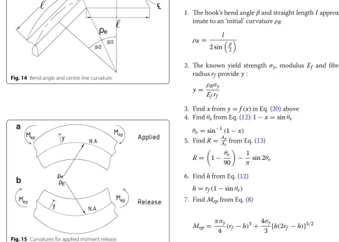
The following seven-steps enable an estimate of the extent of plasticity within the equivalent bend radius of a hooked end fibre.
4 Method
1. The hook’s bend angle β and straight length l
approx-imate to an ‘initial’ curvature ρR
2. The known yield strength σy , modulus Ef and fibre
radius rf provide y:
3. Find x from y=f(x) in Eq. (20) above
4. Find θe from Eq. (12): 1−x=sinθe
5. Find R= AAp
t from Eq. (13)
6. Find h from Eq. (12)
7. Find Mep from Eq. (8)
ρR=
l
2 sinβ2
y= ρRσy Efrf
θe=sin−1(1−x)
R=
1− θe
90
− 1 π sin 2θe
h=rf(1−sinθe)
Mep=
π σy
4 (rf −h)
3+4σy
3 [h(2rf −h)]
3/2
Fig. 13 Curvature for elastic–plastic bending.
Fig. 14 Bend angle and centre line curvature.
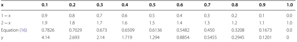
The graph of Table 3 entries in Fig. 16 enables x to be
read from y according to step 3. All fibre geometries lie within the highlighted region shown. Thereafter the calculation of θe and R determine the spread of plastic-ity within the cross-section for a given fibre geometry as shown in Table 4.
5 Incorporating the Elastic–Plastic Moment Expression Into Frictional Pulley Model
The elastic–plastic moment expression proposed above (step 7) has been incorporated into frictional pulley model (Abdallah et al. 2016a) in order to predict the forces at each stage of pull-out for all hooked end fibres. From static force and moment equilibrium, the pull-out force P in each pull-out stage has been determined
(Abdallah et al. 2016a) as given by Eqs. (21)–(24). The present mathematical interpretation of frictional pul-ley model has been explained in detail by Abdallah et al. (2016a).
(21)
�P′= FPH 1−µ×cosβ
(22)
�P′′=
2FPH
1+ 1−µµ××coscosββ
1−µ×cosβ
(23)
�P′′′=
FPH
3+
2µ∗cosβ
1−µ∗cosβ
21+1−µ∗cosµ∗cosββ
+1
(1−µ∗cosβ)
(24)
�P′′′′=
FPH
4+
2µ∗cosβ 1−µ∗cosβ
3+2µ∗cosβ
2
1+ 1−µ∗cosµ∗cosββ
+1
+2
1+ 1−µ∗cosµ∗cosββ
+1
(1−µ∗cosβ)
Table 3 x and y values of Eq. (20).
x 0.1 0.2 0.3 0.4 0.5 0.6 0.7 0.8 0.9 1.0
1 − x 0.9 0.8 0.7 0.6 0.5 0.4 0.3 0.2 0.1 0.0 2 − x 1.9 1.8 1.7 1.6 1.5 1.4 1.3 1.2 1.1 1.0 Equation (16) 0.7826 0.7029 0.673 0.6509 0.6136 0.5482 0.450 0.3208 0.1673 0.0 y 4.14 2.693 2.14 1.719 1.294 0.8854 0.5455 0.2945 0.1201 0
Fig. 16 Normalized curvature (y) versus penetration depth ratio (x).
Table 4 Seven-steps enable an estimate of the extent of plasticity within the equivalent bend radius of a hooked end fibre.
Method 3DH 4DH 5DH
Step 1 ( ρR) 39.2 57.95 62 Step 2 ( y) 0.40 0.74 0.98 Step 3 ( x) 0.74 0.60 0.56 Step 4 ( θe) 15.07 23.57 26.10
Step 5 ( R) 0.67 0.50 0.45
where P′,P′′,P′′′,P′′′′ represent the pull-out force
due to plastic deformation contribution of one, two, three and four plastic hinges, respectively (Abdallah et al. 2016a). By adding the pull-out force at the onset of com-plete debonding P1 to Eqs. (21)–(24), the pull-out force
P as a function of fibre slip in all main stages can be
obtained as follows:
5.1 For 3DH fibre
(25)
P =
P2=P1+�P′′(Eq.(18)) P3=P1+�P′(Eq.(17))
Table 5 The predicted pull-out forces for all hooked end fibres.
Fibre type Matrix type P1 P2 P3 P4 P5
3DH NSC 55 404 264 – –
MSC 76 593 285 – –
HSC 108 625 317 – –
4DH NSC 55 545 454 229 –
MSC 76 766 475 250 –
HSC 108 798 507 282 –
5DH NSC 55 746 834 510 255
MSC 76 1162 855 531 276
HSC 108 1194 887 563 308
5.2 For 4DH fibre
5.3 For 5DH fibre
The P1 value can be predicted using Eq. (28) of straight fibre developed by Naaman et al. (1991a).
where ψ is the fibre perimeter, τfd (∆) is the frictional shear stress function for a slip ∆, and (l − ∆) is the length of fibre remaining embedded.
(26)
P=
P2=P1+�P′′′(Eq.(19)) P3=P1+�P′′(Eq.(18)) P4=P1+�P′(Eq.(17))
(27)
P=
P2=P1+�P′′′′(Eq.(20)) P3=P1+�P′′′(Eq.(19)) P4=P1+�P′′(Eq.(18)) P5=P1+�P′(Eq.(17))
(28)
P1=ψ τfd(�)×(l−�)
6 Model Validation
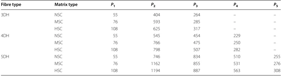
The frictional pulley model predictions using the pro-posed elastic–plastic moment expression presented above was validated against experimental pull-out results for various hooked end fibres. All the material properties of the fibres (fibre geometry and tensile strength) as well as the concrete properties were used as the input param-eters in this model (Tables 1 and 2). The predicted forces ( P1,P2. . .P5 ) at each stage of pull-out for all hooked end
fibres are summarized in Table 5. Here, the continuous pull-out curves shown in Figs. 17, 18 and 19 were fitted numerically to P1,P2. . .P5 using a fifth degree
polyno-mial function (Abdallah et al. 2016a).
The respective figures show the comparison between the predicted and experimental pull-out curves of all hooked end fibres embedded in NSC, MSC and HSC. For each hooked end geometry, the model predictions, exhibited in Figs. 17, 18 and 19, can reasonably well sim-ulate the experimental pull-out load-slip curve. It is clear that the proposed model is able to capture the main fea-tures of pull-out behaviour and to predict accurately the pull-out load-slip curve, irrespectively of fibre geometry and tensile strength. The model takes also into account the mechanical anchorage effect provided by the fibre
hook as well as the variation of the concrete proper-ties. It can be observed that with increasing the matrix strength from NSC to MSC and HSC, the straightening of the hook becomes progressively increased for all fibres (Fig. 10). Therefore, the accuracy of the model predic-tions is increasingly improved for all fibres.
7 Conclusion
In this paper an elastic–plastic response model has been advanced to predict the pull-out behaviour of various hooked end steel fibres embedded in normal, medium and high strength concretes. The model accounts for the amount of deformation and straightening of the hook during the pull-out. The spread of plasticity within hook bends was found to be closely related to matrix strength. The elastic–plastic moment expression developed has been incorporated into frictional pulley model to predict the forces at each stage of pull-out. The input parameters to the model were the mechanical and geometrical prop-erties of the fibres together with the ultimate strength of the concrete grades.
The proposed model has been validated against experimental results for each combination between three hooked end fibres embedded in normal, medium and high strength concretes. The results show that the
method proposed can predict the pull-out-slip response for all hooked end fibres-concrete combination realisti-cally. Predictions show greatest accuracy in matching the pull-out-slip behaviour of hooked end fibres embedded in MSC and HSC. This model was also able to take into account matrix damage and fibre rupture.
Abbreviations
P: pull-out force; ∆: relative slip of the fibre; ∆P: pull-out force due to plastic hinges contribution; PH: plastic hinge; FPH: rotational friction component; I: second moment area; ME: elastic moment; Mep: elastic–plastic moment; Mp: plastic moment; δA: incremental strip area; Ef: fibre modulus; I: the second moment of the section’s area; δy: incremental strip depth; µ: friction coef-ficient; R: penetration depth; IE: the second moment of the fully elastic; rf: fibre radius; σy: fibre yield strength; h: plastic depth; Ef: modulus of elasticity of fibre; θe: angular penetration measure; Af: total area of the steel fibre circular section; Ap: plastic penetration area; ρE: fully elastic curvature; ρe: curvature of inner elastic zone; ρR: initial curvature; εR: residual strain; εe: elastic strain.
Authors’ contributions
Both authors contributed equally to this work. Both authors read and approved the final manuscript.
Acknowledgements
The first author is grateful for the financial support provided by the Ministry of Higher Education and Scientific Research of the Iraqi Government.
Competing interests
The authors declare that they have no competing interests.
Consent for publication
Authors have approved the manuscript and agree with its submission to International Journal of Concrete Structures and Materials.
Ethics approval and consent to participate
This chapter does not contain any studies with human participants performed by any of the authors.
Funding
The first author gratefully acknowledges the scholarship of the Ministry of Higher Education and Scientific Research of Iraqi Government for this Ph.D. project.
Publisher’s Note
Springer Nature remains neutral with regard to jurisdictional claims in pub-lished maps and institutional affiliations.
Received: 20 May 2018 Accepted: 29 January 2019
References
Abdallah, S., & Fan, M. (2017). Anchorage mechanisms of novel geometrical hooked-end steel fibres. Materials and Structures,50(2), 139.
Abdallah, S., Fan, M., & Cashell, K. A. (2017a). Bond-slip behaviour of steel fibres in concrete after exposure to elevated temperatures. Construction and Building Materials,140, 542–551. https ://doi.org/10.1016/j.conbu ildma t.2017.02.148.
Abdallah, S., Fan, M., & Cashell, K. A. (2017b). Pull-out behaviour of straight and hooked-end steel fibres under elevated temperatures. Cement and Concrete Research,95, 132–140. https ://doi.org/10.1016/j.cemco nres.2017.02.010.
Abdallah, S., Fan, M., & Rees, D. W. A. (2016a). Analysis and modelling of mechanical anchorage of 4D/5D hooked end steel fibres. Materials & Design,112, 539–552. https ://doi.org/10.1016/j.matde s.2016.09.107. Abdallah, S., Fan, M., & Rees, D. W. A. (2017c). Effect of elevated temperature on
pull-out behaviour of 4DH/5DH hooked end steel fibres. Composite Struc-tures,165, 180–191. https ://doi.org/10.1016/j.comps truct .2017.01.005. Abdallah, S., Fan, M., & Rees, D. W. (2018a). Bonding mechanisms and strength
of steel fiber-reinforced cementitious composites: Overview. Journal of Materials in Civil Engineering,30(3), 04018001.
Abdallah, S., Fan, M., & Zhou, X. (2017d). Pull-out behaviour of hooked end steel fibres embedded in ultra-high performance mortar with various W/B ratios. International Journal of Concrete Structures and Materials,11, 301–313.
Abdallah, S., Fan, M., Zhou, X., & Geyt, S. (2016b). Anchorage effects of various steel fibre architectures for concrete reinforcement. International Journal of Concrete Structures and Materials,10, 325–335.
Abdallah, S., Rees, D. W., Ghaffar, S. H., & Fan, M. (2018b). Understanding the effects of hooked-end steel fibre geometry on the uniaxial tensile behav-iour of self-compacting concrete. Construction and Building Materials,178, 484–494.
Adjrad, A., Bouafia, Y., Kachi, M., & Ghazi, F. (2016). Prediction of the Rupture of Circular Sections of Reinforced Concrete and Fiber Reinforced Concrete. International Journal of Concrete Structures and Materials,10, 373–381. Alwan, J. M., Naaman, A. E., & Guerrero, P. (1999). Effect of mechanical clamping
on the pull-out response of hooked steel fibers embedded in cementi-tious matrices. Concrete Science and Engineering,1(1), 15–25.
Chanvillard, G. (1999). Modeling the pullout of wire-drawn steel fibers. Cement and Concrete Research,29(7), 1027–1037.
Deng, F., Ding, X., Chi, Y., Xu, L., & Wang, L. (2018). The pull-out behavior of straight and hooked-end steel fiber from hybrid fiber reinforced cementi-tious composite: Experimental study and analytical modelling. Composite Structures,206, 693–712.
El-Mal, H. A., Sherbini, A., & Sallam, H. (2015). Mode II fracture toughness of hybrid FRCs. International Journal of Concrete Structures and Materials,9(4), 475–486.
Georgiadi-Stefanidi, K., Mistakidis, E., Pantousa, D., & Zygomalas, M. (2010). Numerical modelling of the pull-out of hooked steel fibres from
high-strength cementitious matrix, supplemented by experimental results. Construction and Building Materials,24(12), 2489–2506. https ://doi. org/10.1016/j.conbu ildma t.2010.06.007.
Ghoddousi, P., Ahmadi, R., & Sharifi, M. (2010). Fiber pullout model for aligned hooked-end steel fiber. Canadian Journal of Civil Engineering,37(9), 1179–1188.
Isla, F., Ruano, G., & Luccioni, B. (2015). Analysis of steel fibers pull-out. Experi-mental study. Construction and Building Materials,100, 183–193. https :// doi.org/10.1016/j.conbu ildma t.2015.09.034.
Islam, M. S., & Alam, S. (2013). Principal component and multiple regression analysis for steel fiber reinforced concrete (SFRC) beams. International Journal of Concrete Structures and Materials,7(4), 303–317.
Laranjeira, F., Molins, C., & Aguado, A. (2010). Predicting the pullout response of inclined hooked steel fibers. Cement and Concrete Research,40(10), 1471–1487. https ://doi.org/10.1016/j.cemco nres.2010.05.005. Lee, Y., Kang, S., & Kim, J. (2010). Pullout behavior of inclined steel fiber in an
ultra-high strength cementitious matrix. Construction and Building Materi-als,24(10), 2030–2041.
Li, H., & Liu, G. (2016). Tensile properties of hybrid fiber-reinforced reactive powder concrete after exposure to elevated temperatures. International Journal of Concrete Structures and Materials,10, 29–37.
Naaman, A. E., Namur, G. G., Alwan, J. M., & Najm, H. S. (1991a). Fiber pullout and bond slip. I: Analytical study. Journal of Structural Engineering,117(9), 2769–2790.
Naaman, A. E., Namur, G. G., Alwan, J. M., & Najm, H. S. (1991b). Fiber pullout and bond slip. II: Experimental validation. Journal of Structural Engineering, 117(9), 2791–2800.
Nammur, G., Jr., & Naaman, A. E. (1989). Bond stress model for fiber reinforced concrete based on bond stress–slip relationship. ACI Materials Journal, 86(1), 45–57.
Robins, P., Austin, S., & Jones, P. (2002). Pull-out behaviour of hooked steel fibres. Materials and Structures,35(7), 434–442.
Soetens, T., van Gysel, A., Matthys, S., & Taerwe, L. (2013a). A semi-analytical model to predict the pull-out behaviour of inclined hooked-end steel fibres. Construction and Building Materials,43, 253–265.
Soetens, T., van Gysel, A., Matthys, S., & Taerwe, L. (2013b). A semi-analytical model to predict the pull-out behaviour of inclined hooked-end steel fibres. Construction and Building Materials,43, 253–265. https ://doi. org/10.1016/j.conbu ildma t.2013.01.034.
Sujivorakul, C., Waas, A., & Naaman, A. (2000). Pullout response of a smooth fiber with an end anchorage. Journal of Engineering Mechanics,126(9), 986–993.
Tadepalli, P. R., Mo, Y., & Hsu, T. T. (2013). Mechanical properties of steel fibre concrete. Magazine of Concrete Research,65(8), 462–474.
Tuyan, M., & Yazici, H. (2012). Pull-out behavior of single steel fiber from SIF-CON matrix. Construction and Building Materials,35, 571–577. https ://doi. org/10.1016/j.conbu ildma t.2012.04.110.
Won, J., Hong, B., Lee, S., & Choi, S. J. (2013). Bonding properties of amorphous micro-steel fibre-reinforced cementitious composites. Composite Struc-tures,102, 101–109.
Won, J., Lee, J., & Lee, S. (2015). Predicting pull-out behaviour based on the bond mechanism of arch-type steel fibre in cementitious composite. Composite Structures,134, 633–644. https ://doi.org/10.1016/j.comps truct .2015.08.127.
Zendaoui, A., Kadid, A., & Yahiaoui, D. (2016). Comparison of different numeri-cal models of RC elements for predicting the seismic performance of structures. International Journal of Concrete Structures and Materials,10(4), 461–478.