http://www.sciencepublishinggroup.com/j/ajcbm doi: 10.11648/j.ajcbm.20180201.12
Study of Dynamic Behavior of a Three Story Model Frame
Rafiqul Islam
1, *, Md. Tarek Hossain
1, Md. Jahir Bin Alam
2, Mushtaq Ahmed
21
Department of Civil Engineering, Sylhet Engineering College, Sylhet, Bangladesh 2
Department of Civil & Engironmental Engineering, Shahjalal University of Science & Technology, Sylhet, Bangladesh
Email address:
To cite this article:
Rafiqul Islam, Md. Tarek Hossain, Md. Jahir Bin Alam, Mushtaq Ahmed. Study of Dynamic Behavior of a Three Story Model Frame. American Journal of Construction and Building Materials. Vol. 2, No. 1, 2018, pp. 10-15. doi: 10.11648/j.ajcbm.20180201.12
Received: April 9, 2018; Accepted: May 3, 2018; Published: May 30, 2018
Abstract:
Recently earthquake has been occurred several times in many areas of Bangladesh at low to medium intensity. Major cities of Bangladesh are more or less vulnerable to earthquake. It is necessary to develop effective technique for minimizing the severity and often tragic consequences of earthquake. The universities & research institutes of Bangladesh are interested to enhance studies in earthquake engineering. But no facilities were developed to let the students & researchers sound about real earthquake shaking. So in order to develop the knowledge regarding earthquake among the students & researchers it is necessary to introduce a tool which will help them in realizing the earthquake shaking intensity and its vulnerability on different types of civil structure. There are several experimental techniques that can be used to test the response of structure under certain shaking intensity and to verify their seismic performance. One of the popular and efficient techniques is use of an earthquake shaking table. Structural properties (damping ratio, stiffness, natural frequency, natural period, mode shape) of a three story model frame and its deflection behavior under repetitive strong shaking is investigated through shaking table tests. Further effectiveness of various bracing system under multidirectional seismic excitation is analytically investigated also.Keywords:
Structural Dynamics, Earthquake Engineering, Shake Table, Laboratory Tests1. Introduction
The main purpose of testing is to obtain information about the sample or the specimen under study. In structural engineering, it relates to the assessment or investigation of structural or material properties or their verification with theoretical calculations. The initial structural testing can be referred to the earliest stages of development of mechanics and experimentation with the literature referring to tests by Galileo and Newton on plane motion and forces, Hooke on elastic properties [1-4]. However with the availability of several testing facilities alongside the new concepts and methods of structural analysis and design, experiments have played very crucial roles in the development of structural engineering particularly over the last half a century.
A small-scale shake table is a very useful tool for analyzing structural models' dynamic behavior under real forces and for investigation of active and passive structural control systems' efficiency [5-10]. Theoretical principles, forming a basis for numerical modeling of structural dynamic response, should be consistent with real behavior of
structures. `Hands-on' experiments demonstrate basic Concepts in structural dynamics and provide undergraduate students with an opportunity to develop deep understanding of structural response to different dynamic loads. A shake table platform with programmable motion is used to create and apply real loads to structures. The load can be programmed as impulse or continuous, stochastic or prescribed in time and in magnitude. Changing the platform's position is used for creating dynamic loads acting in different directions, including a vertical one. The forces can be applied to an investigated structure by shake table acceleration and they can have a form proportional to the structural element's mass. Another possibility is to apply the loads directly to the structural elements.
2. Methodology
structural design for these dynamic loadings, as well as methods of Protection of structures against disasters. Shake tables of various capacities are used for this reason all over the world [10-11]. However, using big shaking platforms is not always possible because of the high cost of the experiments. Hence small-scale laboratory shake tables have been implemented in the last few decades.
2.1. Earthquake Shaking Table
There are several distinct experimental techniques that can be used to test the response of structures to verify their seismic performance, one of them is the use of an earthquake shaking table (a shaking table, or simply shake table). This is a device used for shaking structural models or building components with a wide range of simulated ground motions, including reproductions of recorded earthquakes time-histories. Modern tables typically consist of a rectangular platform that is driven in up to six degrees of freedom (DOF) by servo-hydraulic or other types of actuators [11-12].
Test specimens are fixed to the platform and shaken, often to the point of failure. Using video records and data from transducers, it is possible to interpret the dynamic behavior of the specimen. Earthquake shaking tables are used extensively in seismic research, as they provide the means to excite structures in such a way that they are subjected to conditions representative of true earthquake ground motions.
2.2. Specifications of the Shake Table
Measuring system of E-Defense is shown in Figure 1 Shake table and its various activities shown in Figure 2 to Figure 5
This facility will be used to reproduce dynamic behavior of full-scale structure models subjected to actual huge earthquakes. Consequently, it will greatly contribute in improving the seismic performance and design of structures. This paper describes the general framework of the research topics utilizing E-Defense.
Table 1. E-Defense specifications.
Types Specifications
Payload 12MN (1200tons)
Size 20m××××15m
Driving Type Accumulator Charge/ Electro-Hydraulic Servo Control
Shaking Direction XY- Horizontal Z- Vertical Maximum Acceleration 900 cm/s2 >1,500cm/s2 Maximum Velocity 200 cm/s 70cm/s Maximum Displacement ±100cm ±50cm
Maximum Allowable Moment Overturning Yaeing 150 MN-m 10MN-m
2.3. Design Consideration
1. Cost of table & materials for model 2. Feasibility of construction
3. Ability of table to take the weight of different materials 4. Direction of motion
5. Frequency intensity
6. Measure the various mode of models motion
2.4. Material Used
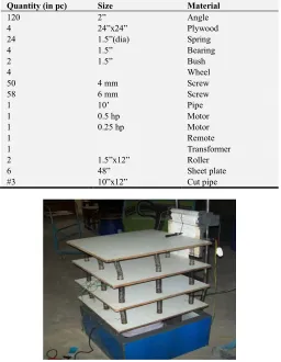
Table 2. Material used for shake table.
Quantity (in pc) Size Material
120 2” Angle
4 24”x24” Plywood
24 1.5”(dia) Spring
4 1.5” Bearing
2 1.5” Bush
4 Wheel
50 4 mm Screw
58 6 mm Screw
1 10’ Pipe
1 0.5 hp Motor
1 0.25 hp Motor
1 Remote
1 Transformer
2 1.5”x12” Roller
6 48” Sheet plate
#3 10”x12” Cut pipe
Figure 1. A Typical view of our Shaking Table.
2.5. Experimental Setup
The laboratory setup of the present work is done in the structural mechanics & strength of materials lab in the department of CEE at SUST. The setup includes a model structure, shaking plate, stiffness measuring device & floor vibration measuring device.
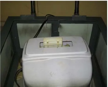
2.6. Description of the Structural Model
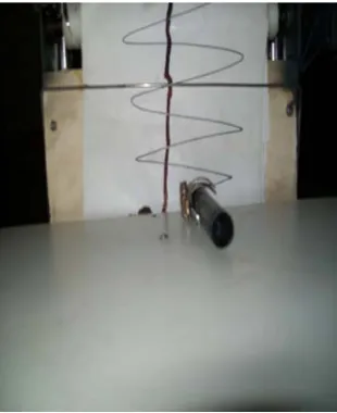
The structural model used in the experimental works is a 3 storied model structure in addition to the ground floor and is about 2 feet high. Each floor is composed of a 2′× 2′ timber plate (modeled as floor slab) and eight helical springs (for columns). They are assumed to provide the entire mass and stiffness respectively of the system.
The ground floor is supported on a four-legged stand by means of four rollers on the four ends. The rollers are attached to the stand. On the top of the ground floor there three floors each supported by springs coiled to the floor below. Without any extra weight, each floor weighs about 4 pounds.
the diameters of the driving and driven pulley. This way, provisions have been made for the model to be vibrated at three different frequencies; i.e., 30, 70 and 110 rpm. A marker can be attached to each floor allowing the displacement to be recorder on a suitable white board or a moving graph paper placed right in front of it.
Figure 2. Motor used in shaking table.
Figure 3. Spring column of model frame.
Figure 4. Slab of model frame.
Figure 5. Data recording system of Shaking table.
2.7. Determination of Structural Property
A structure is characterized by its mass, stiffness and damping. Mass, stiffness of any structure may be obtained from the geometry and material properties of the structure. However, damping of a structure should be determined through experiments. For purpose of this experiment it was assumed that the only damping present in the structure is due to viscous damping. Two commonly used method to determine the damping’s in structures are the logarithmic decrement method and the half power band with method. For this work logarithmic decrement technique has been used to obtain the damping properties of the structure [12-15].
2.7.1. Determination of Damping Ratio
Using free vibration data of the acceleration of the structure one may obtain the damping ratio. The logarithmic decrement δ between two peaks is defined as
δ = ln
Where y1 and y2are the amplitudes of the peaks.
From the solution of the damped system x (t) = (c cos ) t+ Disin t) we can say that y1 and y2 can be written as
y1=
y2=
Where the constant term C includes the term of the sine and cosine in the equation
x (t) = (c cos ) t+ Di sin t) and is the period
of the system. Now using y1= and y2= in
equation δ = ln
δ = ln = ln
=ζ T
When the damping ratio is small can be approximate as
δ = 2πζ
ζ = ! = "# $ $ !
Where
ζ
is the damping ratio of the structure. Determination of StiffnessI = ! %()& '&
Where
I = Inertia of the structure.
D = Outer diameter of the spring column. d = inner diameter of the spring column.
Kc = ,- *+
Kc is the stiffness of the structure. E = Young’s Modulus of steel. L = Length of the spring column.
2.7.2. Determination of Natural Frequency and Natural Mode Shape of the Structure
Determine natural frequency
( )
and natural mode shape (. by eigenvalue problemWe know, KΦ= mΦ
By / 0 gives the standard eigenvalue problem
/ 0 1K / 0 1/0 1
Φ= / 0 1/0 1/0 1Φ
By simplified the above equation we get
Ay= λy
Where
A=/ 0 1K / 0 1
y= /0 1Φ
λ=
Determine the natural frequencies and mode by
=23
. =/ 0 14
Now A=/ 0 1K / 0 1.
Where m is mass matrix and K is stiffness matrix Mass Matrix:
560 60 0 00
0 0 68
9
Stiffness Matrix:
5:0<:; : :<:; :8 <:08
0 <:8 :8
9
2.7.3. Measurement of the Structural Displacements
There are two simple devices used in this work to measure structural displacements. Since there is no facility in this device to record dynamic time dependent motions, it can only provide the consecutive displacement amplitudes of the time series.
The arrangement for recording the displacement can be placed anywhere along its height. Actually, it has been designed to record motions of much larger structural models. The arrangement includes a paper moving over a movable roller, the paper being able to slide over the roller at a certain speed, controlled by an arrangement of pulley systems.
Once the paper starts rolling it can record the motions of any floor as it vibrates with time, the motion being recorded by the marker set at the floor level.
Figure 6. Normal frame system.
Figure 7. Frame system with G. I wire bracing.
Figure 8. Frame system with bamboo stick bracing.
3. Result
3.1. Determination of Structural Property
Table 3. Free vibration test data of three story frame.
Quantity Notation Story
1st 2nd 3rd
Amplitude of peak 1 y1 2 4.2 6.5
Amplitude of peak 2 y2 1.4 3.5 5
Logarithmic decrement δ 0.36 0..18 0.26
Damping Ratio ζ 0.056 0.029 0.042
3.2. Determination of Stiffness
Table 4. Physical properties of parts of the structure.
No Part Material Mass (Kg) Material Properties
Young`s Modulus (E) N/m2 Mass Density (ρ) Kg/m3
1 Column Steel .103 200x109 7850
2 Slab Plywood 3.608 126x105 700
3 Screw Steel .009 200x109 7850
Table 5. Geometrical data of the shake table.
Dimension in mm
Depth (D) Width (B) Length (L) Diameter (Outer) Diameter (Inner) Length
15 610 610 32 25 160
3.3. Determination of Natural Frequency and Natural Mode Shape
Table 6. Natural frequencies of a three story building frame.
Mode No Natural frequencies Mode shapes
Circular(rad/sec) Cyclic (Hz) Natural period (Sec) 3-DOF model 1 7.04 ∗ 108 1.12 ∗ 108
0.0010 2.79 2.70 -0.16
2 3.79 ∗ 108 0.603 ∗ 108
0.0020 2.79 -3.17 0.82
3 4.40 ∗ 108 0.70 ∗ 108
0.0014 0.45 0.38 -0.82
3.4. Analysis of the Structural Vibration
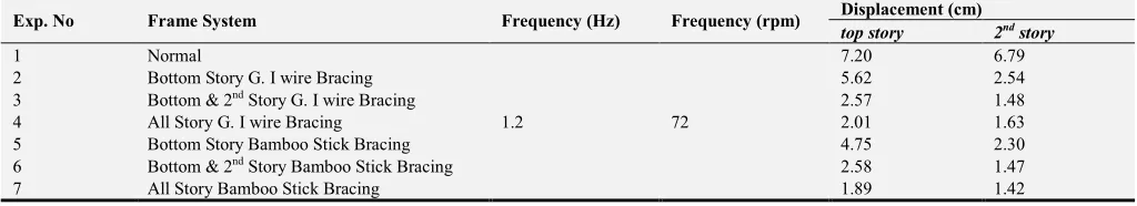
Table 7. Displacement of Story at 78 rpm frequency.
Exp. No Frame System Frequency (Hz) Frequency (rpm) Displacement (cm)
top story 2nd story
1 Normal
1.3 78
7.80 7.30
2 Bottom Story G. I wire Bracing 6.11 2.75
3 Bottom & 2nd Story G. I wire Bracing 2.98 1.60
4 All Story G. I wire Bracing 2.17 1.77
5 Bottom Story Bamboo Stick Bracing 5.15 2.49
6 Bottom & 2nd Story Bamboo Stick Bracing 2.80 1.60
7 All Story Bamboo Stick Bracing 2.05 1.54
Table 8. Displacement of story at 72 rpm frequency.
Exp. No Frame System Frequency (Hz) Frequency (rpm) Displacement (cm)
top story 2nd story
1 Normal
1.2 72
7.20 6.79
2 Bottom Story G. I wire Bracing 5.62 2.54
3 Bottom & 2nd Story G. I wire Bracing 2.57 1.48
4 All Story G. I wire Bracing 2.01 1.63
5 Bottom Story Bamboo Stick Bracing 4.75 2.30
6 Bottom & 2nd Story Bamboo Stick Bracing 2.58 1.47
4. Discussions
Damping Ration of the model frame is 0.056, 0.029 & 0.042 for bottom, 2nd & top story respectively. Natural frequency of the model frame is 1. 12 ∗ 108Hz, 0.603 ∗ 108Hz & 0. 703 ∗ 108Hz. Natural time period of the model frame is 0.0010 sec, 0.0020 sec & 0.0014 sec. According to observation it was found that second story deflection with bottom and 2nd story G. I wire bracing was less than that of all story G. I wire bracing system. Perhaps the region behind this phenomenon is inertia of mass of top story which tend to move in opposite direction while integrated bottom and second story move other direction. But when braced all story it’s deflect like an integrated structure.
In case of bamboo stick bracing system it was found that deflection reduced consecutively as we braced bottom, 2nd and all story respectively which followed Earthquake resisting properties. Bamboo stick bracing system performed better than G. I wire bracing system because of G. I wire only carries tensile force. Other hand, bamboo stick carries both tensile and compressive force. In case of top story deflecting with bottom story bracing bamboo stick bracing performed 12% less deflection than G. I wire bracing. In case of top story deflecting with bottom & 2nd story bracing bamboo stick bracing performed 1% less deflection than G. I wire bracing. In case of top story deflecting with all stories bracing bamboo stick bracing performed 1.5% less deflection than G. I wire bracing. In case of 2nd story deflecting with bottom story bamboo stick bracing performed 3.6% less deflection than G. I wire bracing. In case of 2nd story deflecting with bottom & 2nd story bracing bamboo stick bracing performed 0.2% less deflection than G. I wire bracing. In case of 2nd story deflecting with all stories bracing bamboo stick bracing performed 3% less deflection than G. I wire bracing.
5. Conclusion
In this work the behavior of a three storied building frame model subjected to harmonic base motion was studied. These experiments enable the understanding of occurrence of resonance phenomenon in simple multi-degree of freedom (MDOF) systems. Stiffness and mass distribution properties of analyzed frame were uniformly distributed in plan as well as in elevation. The frame was designed to facilitate the visualization of the first three mode shape with bare eyes. Also the frame was so configured that three degree of freedom would serve as a reasonable approximation. The frame has used a model for a building frame with three floors
which experienced Earthquake like base motion. The frequency of base motion can be varied by changing the rpm of electric motor.
References
[1] M. A. Ansary, Installation of Earthquake monitoring system, 2006
[2] www.ijee.dit.ie/usr/local/etc/sAmPiE/volume25-1
[3] I. Marginean, F. Dinu, D. Dubina, Simulation of the dynamic response of steel moment frames following sudden column loss. Experimental calibration of the numerical model and application. 2018. DOI: 10.1002/stco.201810012
[4] Stylianidis, P: Nethercot, D. Considerations for Robustness in the Design of Steel and Composite Frame Structures. Structural Engineering International. 2017;27:263-80
[5] G. Agranovich, Y. Ribakov and B. Blostotsky, Reproducing Earthquake Using Shaking Tables with Limited Displacement, European Earthquake Engineering, 1, 2007, pp. 16-25. [6] C. H. Dowding, Construction Vibrations, Prentice Hall, Inc.
(1996).
[7] B. Zalewski and A. Huckelbridge, The Dynamic Load Environment of Bridge-Mounted Sign Support Structures, Final report, Ohio Department of Transportation (FHWA) (2005).
[8] http://www.aij.or.jp/jpn/symposium/2006/loads/loads.htm [9] Joint Committee on Structural Safety, Probabilistic Model
Code, (2001).
[10] http://earthquake.usgs.gov/earthquakes/recenteqsww/Maps/re gion/Asia.php
[11] World Large Scale Shake Table- www.engr.colostate.edu/NEESWood/
[12] www.thetech.org/education The Tech Museum of Innovation 201 South Market Street, San Jose, CA 95113 Phone: 408-795-6240
[13] Web Resources (Visit www.raft.net/more for how-to videos and more ideas!). Descriptions of the 4 waves – http://www.geo.mtu.edu/UPSeis/waves.html. “Earthquakes for Kids” and more – http://earthquake.usgs.gov/learning/kids.php Developed by RAFT Education Department
[14] www.raft.net/more & http://earthquake.usgs.gov/ Developed and written by Coral Clark (RAFT))