44 | P a g e
DESIGN AND IMPLEMENTATION OF
MULTITASKING FLYING ROBOT (QUADCOPTER)
CONTROLLED BY ANDROID APPLICATION
Sahyadri R. Mane
1, Prakash S. Andhare
2, Swapnali B. Gaikwad
31,2,3
Fabtech Technical Campus College of Engg. Sangola, Solapur,
ABSTRACT
Nowadays, technology of science is developing very fast. Quadcopter is not a new concept in the fastest developing technology. Quadcopters are used for video recording or image capturing in case of defense in surveillance. The “multitasking flying robot” is used for observing in the agricultural field and to carry the
weight from one place to another place. It is used to locate the video camera for long distance communication. It requires small guidance for navigation and control system to be developed and tested. There are several methods to do the control quad copters such as Zigbee, Wi-Fi, Bluetooth and GSM. GSM (Global system for mobile communication) technology is used for communication. The robot is wirelessly controlled by GSM based android application. It can perform functions like temperature and humidity sensing and obstacle detection. Signals are transmitted wirelessly through the mobile application to quad copter. All the operations are performed on the basis of microcontroller/Arduino Uno which is the master in doing operations in simple way. This paper focuses hardware and software level of design aspects. It have capabilities like seeing and detection of obstacle and give the notification to the transmitter side means mobile act as a trans-receive. Quadcopter maintain stable position when flying. Quadcopter accept load disturbance up to 100g during hover condition. Approximate time of operated quadcopter is 3 minutes using 1500mAh battery and operate time can be increased by using largest battery capacity. In the multitasking flying robot is efficient utilization of resources and reduce labor work.
Keywords: Android application, Arduino board, GSM module, Quadcopter, Navigation, Sensors.
I. INTRODUCTION
Multitasking flying robotic systems are used to implement into transportation field as a carrier to carry some
weight from one place to another place without damaging it. Thrust concept is used for standing delivery to
weight. It requires some mechanical force to generate thrust, due to this it becomes easy delivery of weight. This
is one of the multitasking flying robot application, another applications are image capturing, video transmission
and reception, temperature and humidity sensation. Quadcopter required dynamics in order to account for
gravity effect and aerodynamic forces. It operated by thrust that produce by four motor that attach to the
quadcopter body. Quadcopter changes direction by manipulating transmitter side of mobile. From the
45 | P a g e
construction , operation, and application of robots, as well as computer system for their control, sensory
feedback, and information processing[6].
The camera used for image capturing and video recording in that Quadcopter which rotates in 3600 vertically
and horizontally for any target. Using PIR sensor it perform human detection, it can rotate 180x180 horizontal to
vertical range to get target motion. Flying robot has night vision camera for capturing continuous live streaming
and send to the control unit. All this system controlled by a single microcontroller[7]. Use of a mobile phone for
flying robot control can overcome these limitations. It provides the advantages of robust control, working range
as large as the coverage area of the service provider, no interference with other controllers and up to controls. So
This system will be a powerful and flexible that will offer this service at any time, and from anywhere with the
constraints of the technologies being applied. Possible target appliances include climate control systems[8].
This paper divides into five sections first section (I) is about to Introduction of multitasking flying robot
(Quadcopter). In the second section (II) mentioned that the system development of the multitasking flying robot.
After the system development third section (III) mentions that experimental result of the project. In the fourth
section (IV) the conclusion gives the output of the system.
II. SYSTEM DEVELOPMENT
This multitasking flying robot consist of two types of design-
a) Hardware design
b) Software design
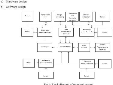
Fig 1: Block diagram of proposed system
A central controller controls the robot prototype and different modules are interfaced with a single controller on
the arduino board. The multitasking flying robot has ATMEGA328P controller at its core. It is interfaced with
GSM module for communication with the base station. It is connected to L293D motor driver IC for the control
of the robot motion. The overall system controlled android application and performs the operation. The signals
46 | P a g e
the acknowledgement to the transmitter side. And the performing operations display on the mobile screen
where we can sends the signals.
Arduino board-
Fig 2: Arduino Board
Table 1. Specification of Arduino Board
Arduino/Genuino Uno is a microcontroller board based on ATmega328P. It has 14 digital input/output pins (out
of which 6can be used as PWM outputs), 6 analog inputs, a 16MHz quartz crystal, a USB connection, a power
jack, an ICSP header and a reset button. It contains everything needed to support the microcontroller; Simply
connect it to a computer with a USB cable or power it with a AC-to-DC adapter or battery toget started. In the
Arduino board the Atmega328P controller is used which have following specifications- The Atmega328Pis a
high performance microchip Picopower 8 bit AVR RISC based microcontroller combines 32KB flash memory
with read while write capabilities and 1K EPROM data memory, 2K SRAM data memory. 28 pins AVR
controller. I/O pins 23, Timers- two 8-bit/ one 16-bit, PWM six channels. Many instructions are executed in a
single clock. In arduino board, The Atmega328P the microcontroller chip is
used.
The Atmega328P is moreadvanced chip and it is also upgraded.
Accelerometer and
Gyroscope-Anaccelerometer are highly sensitive accelerometer are components of inertial navigation systems for aircraft
and missiles. Accelerometers are used to detect and monitor vibration in rotating machinery. It used in tablet
computers and digital cameras so that images on screens are always displayed upright. In drone, accelerometer
is used for flight stabilization. Coordinated accelerometers can be used to measure differences in acceleration,
particularly gravity, over their separation in space; i.e., gradient of gravitational field. This gravity gradiometry
is useful because absolute gravity is a weak effect and depends on local density of the earth which is quite
variable. For example, an accelerometer at rest on the surface of the earth will measure an acceleration due to
earth’s gravity, straight upwards of g≈9.81m/s2. Accelerometers in free fall will measure zero [6]. Single and
Microcontroller ATmega328P
Operating voltage 5V
Input voltage 7-12V
Input voltage (limit) 6-20V
Digital I/O pins 14(of which 6 provides PWM output)
Flash memory 32KB(ATmega328P) of which 0.5KB
used by bootloader.
SRAM 2KB(ATmega328P)
EEPROM 1KB(ATmega328P)
47 | P a g e
multi-axis models of accelerometer are available to detect magnitude and direction of proper acceleration, as a
vector quantity, and can be used to sense orientation, coordinate acceleration, vibration, shock, and falling in a
resistive medium.
Fig 3: Accelerometer image Fig 4: Implementation of Quadcopter
A gyroscope is a spinning wheel or disc in which the axis of rotation is free to assume any orientation by itself.
When rotating, the orientation of this axis unaffected by tilting or rotation of the mounting , according to
conservation of angular momentum. Because of this, gyroscope are useful for measuring or maintaining
orientation
.
GSM-
GSM (Global System for Mobile communication) is a digital mobile telephony system widely used in world.
GSM uses a variation of time division multiple access (TDMA) and is most widely used of three digital wireless
telephony technologies (TDMA,GSM and CDMA). GSM digitizes and compresses data, then sends it down a
channel with two other streams of user data, each in its own slot. It operates at either the 900 MHz or 1800 MHz
frequency band.
Sensor- Sensor is an electronic component which is used for detect events or changes in its environment And
sends the information to other electronics, frequently a computer processor. It is capable of converting any
physical quantity to be measured into a signal which can be read, displayed, stored or used to controlsome other
quantity.
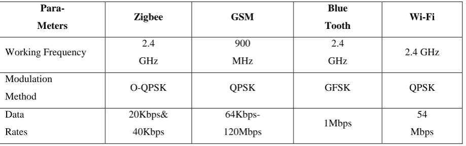
Table 2: comparisons between several communication technology
Para-
Meters Zigbee GSM
Blue
Tooth Wi-Fi
Working Frequency 2.4
GHz
900
MHz
2.4
GHz 2.4 GHz
Modulation
Method O-QPSK QPSK GFSK QPSK
Data
Rates
20Kbps&
40Kbps
64Kbps-
120Mbps 1Mbps
54
48 | P a g e
Transmitter
Current 23mA
380mA (M)
30mA (I) 15mA 4 to 20 mA
Operating
Temp
-20°
To 50° -30° to 60°
-40° to
125° -20°to 60°
This signal produced by the sensor is equivalent to the quantity to be measured.Sensors are used to measure a
particular characteristic of any object or device.
b)Software Development-
Arduino Software- For The arduino integrated development environment – or arduino software(IDE)- contains a
text editor for writing code, a message area, a text console, a toolbar with buttons for common functions and a
series of menus. It connects to the arduino/Genuino hardware to upload programs and communicate with them.
Tools-for selecting hardware programmer when programming a board or chip and using the onboard USB-serial
connection normally you won’t need this, but if you are burning a bootloader to a microcontroller, you will be
use this.
Arduino Programming-
The Arduino/Genuino Uno can be programmed with the (Arduino Software(IDE)). Select “Arduino/Genuino
Uno from the tools> Board menu(according to microcontroller on your board). The ATmega328P on the
Arduino/Genuino Uno comes preprogrammed with the bootloader that allows you to upload new code to it
without the use of an external hardware programmer. It communicates using the original STK500 protocol and
you can also bypass the bootloader and program the microcontroller through the ICSP(In-Circuit Serial
Programming) header using Arduino ISP or similar.
For the development of GSM based android application by using
JAVA: Java is a set of several computer software products and specifications from Oracle Corporation that
provides a system for developing application software and deploying it in a cross-platform computing
environment. Java is used in a wide variety of computing platforms from embedded devices and mobile phones
on the low end, to enterprise servers and supercomputers on the high end.
ECLIPSE INDIGO IDE
49 | P a g e
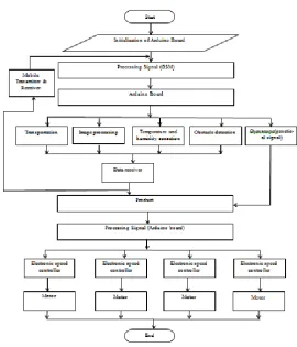
Flow Chart of Proposed System-
Fig 4: Flow chart Proposed System of overall multitasking flying robot
III. EXPERIMENTAL RESULTS
The proposed solutions have been designed using Arduino software and eclipse. It have capabilities like seeing
and detection of obstacle and give the notification to the transmitter side means mobile act as a trans-receive.
Quadcopter maintain stable position when flying. Quadcopter accept load disturbance up to 100g during hover
condition. Approximate time of operated quadcopter is 3 minutes using 1500mAh battery and operate time can
be increased by using largest battery capacity. In the multitasking flying robot is efficient utilization of resources
and reduce labor work. This overall system controlled by using android application. The signals are transmitted
and received by using GSM module.
IV. CONCLUSION
This paper concludes that the “Multitasking flying robot” has performed their work properly. Such kind of
Quadcopter is useful for multipurpose works. Quadcopter makes difficult work easy for the people. This
Quadcopter gives us the temperature and humidity sensation of environment as well as transportation makes
easy by detecting any obstacle in their path. If there is any obstacle detects, then it gives the notification to the
transmitter side. This system operated totally on a single controller
.
50 | P a g e
In the future the multitasking flying robot used in agricultural field for monitoring the farm, industrial purpose,
weather forecasting, image capturing, video recording, also it will used in surveillance system.
REFERENCES
Theses:
[1.] Henrik B. Christophersen*, Wayne J. Pickell*, Adrian A. Koller†, Suresh K. Kannan and Eric N. Johnson‡Georgia“Small Adaptive Flight Control Systems for UAVs using FPGA/DSP Technology”
Institute of Technology, Atlanta GA 30332-0150.
[2.] Gerald MiesFanuc“Military robots of the present and the future”,Robotics Deutschland GmBH, 73765
Neuhausena.d. F., Germany, Vol. 9, No. 1 (2010) 125–137. Received: May 31, 2010.
[3.] Matt Parker, Chris Robbiano,GeradBottorff.“ Quadcopter”, First Semester Report Fall Semester 2011, by Department of Electrical and Computer Engineering, Colorado State University Fort Collins, Colorado
80523.
[4.] MongkhunQetkeaw A/L Vechian, “Wireless Control Quadcopter with Stereo Camera and Self-Balancing System”, A project report, Degree of Master of Electrical Engineering ,Faculty of Electrical and
Electronics Engineering, University Tun Hussein Onn Malaysia, JULY 2012.
[5.] JieLiu ,Edward A. Lee,“Timed Multitasking for Real-Time Embedded Software”, Department of EECS
University of California, Berkeley.
Journal Papers:
[6.] AshishLalwani, MrunmayiBhide, S. K. Shah.“A Review: Autonomous Agribot for Smart Farming”
Proceedings of 46th IRF International Conference, 27th December 2015, Pune, India, ISBN: 978-93-85832-97-0.
[7.] Ashika A.K., Chaithra C.P., Bhavya S.N., G.R. Bharani, Vinutha“Design and Implementation of Multitasking Robotic System for Defence”, International Journal of Advanced Research in Electronics and
Communication Engineering (IJARECE) Volume 5, Issue 5, May 2016 1497.
[8.] Amritanshu Srivastava, Hrishikesh Narayan Tripathi,” GSM Calling based Multi-tasking Robot vehicle
with Password protection” International Journal of Advanced Research in Computer Science and