Free Vibration Analysis of Laminated Functionally
Graded Carbon Nanotube-Reinforced Composite
Doubly Curved Shallow Shell Panels Using a New
Four-Variable Refined Theory
Vu Van Tham, Tran Huu Quoc * and Tran Minh Tu
Faculty of Industrial and Civil Engineering, National University of Civil Engineering, Hanoi 100000, Vietnam; [email protected] (V.V.T.); [email protected] (T.M.T.)
* Correspondence: [email protected]; Tel.:+84-916-600-081
Received: 31 October 2019; Accepted: 28 November 2019; Published: 1 December 2019
Abstract:In this paper, a new four-variable refined shell theory is developed for free vibration analysis of multi-layered functionally graded carbon nanotube-reinforced composite (FG-CNTRC) doubly curved shallow shell panels. The theory has only four unknowns and satisfies zero stress conditions at the free surfaces without correction factor. Five different types of carbon nanotube (CNTs) distribution through the thickness of each FG-CNT layer are considered. Governing equations of simply supported doubly curved FG-CNTRC panels are derived from Hamilton’s principle. The resultant eigenvalue system is solved to obtain the frequencies and mode shapes of the anti-symmetric cross-ply laminated panels by using the Navier solution. The numerical results in the comparison examples have proved the accuracy and efficiency of the developed model. Detailed parametric studies have been carried out to reveal the influences of CNTs volume fraction, CNTs distribution, CNTs orientation, dimension ratios and curvature on the free vibration responses of the doubly curved laminated FG-CNTRC panels.
Keywords: free vibration analysis; doubly-curved shell and panel; nano-composites; functionally graded carbon nanotube-reinforced composite (FG-CNTRC); four-variable refined shell theory
1. Introduction
Functionally graded carbon nanotube-reinforced composites were first proposed by Shen [1] and have been widely accepted as a new advanced material. In functionally graded carbon nanotube-reinforced composite (FG-CNTRC) structures, the CNTs are assumed to be distributed and functionally graded with certain rules along the desired direction to improve the mechanical properties of the structures. Due to the curvature effect, doubly curved shell structures possess increased structural stiffness as compared to flat ones. Therefore, doubly curved shells are often employed to fabricate structural elements of modern constructions made of advanced materials in various engineering disciplines such as aerospace, civil, marine and mechanical engineering. It is thus significant and very meaningful to explore the mechanical response of doubly curved shells made of laminated FG-CNTRC.
Due to its simplicity and effectiveness, the equivalent single-layer model is used for multi-layer composite materials. Among the equivalent single layer models, the model based on the classical theory (CPT) [2] only provides accurate results for the thin shell because it completely neglects the effect of shear deformation. To overcome the limitations of CPT, the model based on the first-order shear deformation theory (FSDT) [3] takes into account the shear deformation effects and provides relatively accurate results for both thin and moderately thick shells, but it has to use shear correction
factor. Therefore, the model based on the higher-order shear deformation theory (HSDT) [4–6] is often desirable. However, it is not convenient to use HSDT because the equations of motions based on HSDT are complicated and difficult to solve. Therefore, the development of simple HSDT is needed. In addition to these, a four-variable deformation theory [7–11] has been developed and applied recently. In this theory model, the transverse shear stresses are satisfied to be parabolic and to be zero on free surfaces. Furthermore, it has only four unknowns, thus the governing equations can be reduced to four.
Based on the above-mentioned theories, various studies have been done to investigate the bending, buckling and vibration responses of FG-CNTRC shells and panels. Using the third-order shear deformation theory, Mehrabadi and Aragh [12] investigated static behavior of FG-CNTRC cylindrical shells. Aragh et al. [13] and Yas et al. [14] studied free vibration of FG-CNTRC cylindrical panels. Alibeigloo [15] analyzed the free vibration behavior of the FG-CNTRC cylindrical panel embedded in piezoelectric layers based on the three-dimensional theory of elasticity and the state-space technique. Lei et al. [16] presented the first-known dynamic stability of FG-CNTRC cylindrical panels under static and periodic axial force. Rasool el al. [17] analyzed the stress wave propagation of FG-CNTRC cylinders subjected to an impact load by using an element-free method. In [18], Shen and Zhang investigated thermal post-buckling of FG-CNTRC cylindrical shells subjected to a uniform temperature rise. Based on a HSDT with a von Kármán-type of kinematic nonlinearity, Shen [19] presented the thermal post-buckling and torsional post-buckling of FG-CNTRC cylindrical shells. Furthermore, Shen and Xiang also performed research on nonlinear vibration [20], and post-buckling [21] behavior of FG-CNTRC cylindrical shells in the thermal environment. A post-buckling analysis of FG-CNTRC cylindrical panels subjected to axial compression was also presented by Liew et al. [22]. In this study, Liew et al. used a meshless approach and arc-length method combined with the modified Newton–Raphson method to trace the post-buckling path. Using the element-free kp-Ritz method, Lei et al. [23] investigated free vibration of FG-CNTRC rotating cylindrical panels. Based on the generalized differential quadrature method (GDQM)and the finite element (FE) method, Tornabene et al. [24] and Thomas et al. [25], respectively, investigated free vibration of FG-CNT-reinforced laminated composite doubly curved shells.
The purpose of this paper is to develop a new four-variable refined shell theory for free vibration analysis of multi-layered functionally graded carbon nanotube-reinforced composite doubly curved panels. The present theory has only four unknowns but it satisfies the stress-free boundary conditions on the top and bottom surface without using shear correction factors. The distribution of the carbon nanotube (CNT) through the thickness of each layer may be functionally graded or uniformly distributed. The resultant eigenvalue system is solved to obtain the frequencies and mode shapes of the anti-symmetric, cross-ply laminated panels by Navier solution. The accuracy of the presented formulation is investigated by comparing the obtained natural frequencies with existing results in the literature. Also, a novelty parameter study of the laminated FG-CNTRC doubly-curved panels of which the geometrical parameters, CNTs distributions, the volume fraction of CNTs, as well as the number of layers are also reported in detail.
2. Theoretical Formulations
2.1. Description of the Model
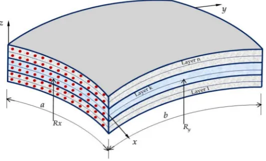
As shown in Figure1, a doubly curved FG-CNTRC shell panel in the orthogonal curvilinear coordinate system (x, y, z) is considered as the modal analysis. The panel has curvilinear lengthain thex-direction, curvilinear widthbin they-direction, thicknesshin thez-direction. In the middle surface of the panel, the principal radii of curvature, denoted byRxandRy, are assumed as constants.
This results in unit Laméparameters. Here, four special kinds of the doubly curved shell panels are investigated such as plate (PLA,Rx=Ry=∞), cylindrical (CYL) panel (Rx=RandRy=∞), spherical
Figure 1. Schematic of the laminated functionally graded carbon nanotube-reinforced composite (FG-CNTRC) doubly curved panel.
2.2. Material Properties of Functionally Graded Carbon Nanotube-Reinforced Composite
In the present study, the lamina is assumed to be perfectly bonded at layer interfaces. As shown in Figure2, five types of functionally graded distributions of CNTs in each layer are taken into consideration, named as UD, FG-A, FG-V, FG-X and FG-O.
Figure 2.Configurations of the FG-CNTRC panels: (a) UD; (b) FG-A; (c) FG-V; (d) FG-X; (e) FG-O.
For these cases, the CNT volume fractions are given as [26]:
UD: VCNT(z) =V∗CNT;
FG−V: VCNT(z) =2V∗
CNT z−zk
zk+1−zk;
FG−A: VCNT(z) =2V∗
CNT zk+1−z
zk+1−zk;
FG−O: VCNT(z) =2V∗
CNT
1−|2z−zk−zk+1|
zk+1−zk
;
FG−X: VCNT(z) =2V∗
CNT
|2z−z
k−zk+1|
zk+1−zk
(1)
wherezkandzk+1are the coordinates of thek-th layer to the reference plane (z=0). V ∗
CNTis the given
volume fraction of CNTs and can be calculated as:
VCNT∗ = wCNT
wCNT+ (ρCNT/ρm)−(ρCNT/ρm)wCNT
in which,wCNTis the mass fraction of the carbon nanotube,ρmandρCNTare mass densities of the
matrix and the CNT, respectively. The effective material properties of FG-CNTRC of each layer can be expressed by the extended rule of the mixture as follows [27]:
E11(z) =η1VCNT(z)ECNT11 +Vm(z)Em η2
E22(z) =
VCNT(z) ECNT
22
+Vm(z) Em ;
η3
G12(z)=
VCNT(z) GCNT12 +
Vm(z) Gm ;
ρ(z) =VCNT(z)ρCNT+Vm(z)ρm;
ν12 =V∗CNTνCNT12 +Vm(z)νm
(3)
whereECNT11 , ECNT22 , EmandGCNT12 , Gmare the Young’s moduli and shear modulus of CNT and matrix; η1,η2andη3are CNT/matrix efficiency parameters;VCNT(z)andVm(z)are volume fractions of CNT
and matrix, and are related byVCNT(z) +Vm(z) =1;vCNT12 andvmare Poisson’s ratio of CNT and matrix.
2.3. Kinematic Relations
This work aims to establish a new shear deformation shell theory. The main idea of the present theory comes from the four-variable refined theory [8,9,11,28,29]. According to assumptions of various four-variable refined theories, the transverse displacementwis partitioned into the bending componentwband shear componentws, the in-plane displacementsuandvare also partitioned into
the extension componentu0,v0, the bending componentub,vb, and shear componentus,vs. Therefore,
the displacement field in the doubly curved shell space can be expressed as follows:
u(x,y,z,t) =1+Rz
x
u0(x,y,t)−z∂wb(∂xx,y,t)−f(z)∂ws(∂xx,y,t)
v(x,y,z,t) =
1+Rz
y
v0(x,y,t)−z∂wb∂(xy,y,t)−f(z)∂ws(∂xy,y,t)
w(x,y,z,t) =wb(x,y,t) +ws(x,y,t)
(4)
whereu0,v0denote the displacements alongxandycoordinate directions of the corresponding point on the reference surface;wbandwsare the bending and shear components of the transverse displacement,
respectively; f(z)represents shape function determining the distribution of the transverse shear strains and stresses along the thickness. By the same methodology, in the previous study [29], we proposed a new shape function f(z)as follows:
f(z) =z "
−1 8 +
3 2
z h
2#
(5)
Detail steps to construct this shape function for shell panels are listed in AppendixA. The strains associated with the displacement field in Equation (4) are:
εxx = 1+z1/Rx
h ε0
x+zκbx+f(z)κsx
i ; εyy= 1+z1/Ry
h ε0
y+zκby+f(z)κsy
i ; γxy= 1+z1/Rx
h γ0
xy+zκbxy+f(z)κsxy
i
+1+z1/R
y
h γ0
yx+zκbyx+f(z)κsyx
i ; γxz= 1+z1/Rxg(z)γsxz;
γyz= 1+z1/Ryg(z)γsyz
where:
ε0
x=
∂u
0
∂x + wb Rx +
ws Rx
; γ0xy= ∂∂vx0;
ε0
y=
∂v0
∂y + wb Ry +
ws Ry
; γ0yx= ∂∂uy0;
kbx=
1
Rx
∂u0
∂x − ∂w2
b
∂x2
; κby=
1
Ry
∂v0
∂y − ∂w2
b
∂y2
; κb xy= 1 Ry
∂v0
∂x − ∂w2b ∂x∂y
; κbyx =
1
Rx
∂u0
∂y − ∂w2b ∂x∂y
;
ksx=−∂
2ws
∂x2 ; ksy=−∂
2ws
∂y2 ; κsxy= ∂
2ws
∂x∂y; κsyx =−∂
2ws
∂x∂y;
γxz= 1+z1/Rxg(z)∂∂wxs; g(z) = (1−f0(z));
γyz= 1+z1/Rxg(z)∂∂wys
(7)
The constitutive relation for an individual layer can be determined by the generalized Hooke’s law, namely [30,31]:
σk xx σk yy τk yz τk xz τk xy =
Qk11 Q
k
11 0 0 Q
k
16
Qk12 Q
k
22 0 0 Q
k
26
0 0 Qk44 Q
k
45 0
0 0 Qk45 Q
k
55 0
Qk16 Q
k
26 0 0 Q
k 66 εxx εyy γyz γxz γxy (8)
whereQki jare the transformed material constraints expressed in terms of material constants:
Qk11=Q11cos4θk+2(Q12+2Q66)sin2θkcos2θk+Q22sin4θk;
Qk12= (Q11+Q22−4Q66)sin2θkcos2θk+Q12
sin4θk+cos4θk;
Qk22=Q11sin4θk+2(Q12+2Q66)sin2θkcos2θk+Q22cos4θk;
Qk16= (Q11−Q12−2Q66)sinθkcos3θk+ (Q12−Q22+2Q66)sin3θkcosθk;
Qk26= (Q11−Q12−2Q66)sin3θkcosθk+ (Q12−Q22+2Q66)sinθkcos3θk;
Qk66= (Q11+Q22−2Q12−2Q66)sin2θkcos2θk+Q66
sin4θk+cos4θk;
Qk44=Q44cos2θk+Q55sin2θk;
Qk45= (Q55−Q44)cosθksinθk;
Qk55=Q55cos2θk+Q44sin2θk.
(9)
in which,Qi jare the plane stress-reduced stiffnesses defined in terms of the engineering constants in
the material axes of the layer. For each CNT layer:
Q11= 1−E11ν12(zν)21; Q12=
ν12E22(z)
1−ν12ν21; Q22=
E22(z) 1−ν12ν21;
Q44=G23(z); Q55=G13(z); Q66=G12(z)
2.4. Governing Equations
Hamilton’s principle is used herein to derive the equations of motion. In the absence of external forces, the principle can be stated in the analytical form as [32]:
Z t2
t1
(δU−δK)dt=0 (11)
whereδUis the variation of the strain energy,δKis the variation of the kinetic energy,t1andt2are arbitrary time variables. The strain energy of the plate can be calculated as:
U = 12
a R 0 b R 0 h/2 R
−h/2
σxxεxx+σyyεyy+τxyγxy+τxzγxz+τyzγyz
1+Rz
x
1+Rz
y
dzdydx
= 12
a R 0 b R 0
Nxxε0xx+Nyyε0yy+Nxyγ0xy+Nyxγ0yx+Mxxb κbxx+Mbyyκbyy+Mbxyκbxy+Mbyxκbyx+
Msxxκsxx+Msyyκsyy+Msxyκxys +Msyxκsyx+Qysγsyz+Qxsγsxz
dxdy
(12)
where stress resultants (N, MandQ) are defined by: Nxx Nxy Qxs = n P
k=1
Rzk+1
zk
1+Rz
y σk xx σk xy τk xz dz; Nyy Nyx Qys = n P
k=1
Rzk+1
zk
1+Rz
x σk yy σk yx τk yz dz; (
Mbxx
Mbxy
) = Pn
k=1
Rzk+1
zk
1+Rz
y
( σk
xx σk xy ) zdz; ( Mbyy Mbyx
) = Pn
k=1
Rzk+1
zk
1+Rz
x
( σkyy σk
yx
) zdz; (
Msxx
Msxy
) = Pn
k=1
Rzk+1
zk
1+Rz
y
( σk
xx
σk xy
) f(z)dz;
( Msyy Msyx
) = Pn
k=1
Rzk+1
zk
1+Rz
x
( σkyy σk
yx
) f(z)dz.
(13)
Based on the constitutive relations (8), strain-displacement relation (6) and displacement field (4), the force and moment resultants can be rewritten in terms of displacement components as:
Nxx Nyy Nxy Nyx
Mbxx
Mbyy Mbxy Mbyx Msxx Msyy
Msxy
Msyx
=
A11 A12 A16 A16 B11 B12 B16 B16 B
s
11 Bs12 B
s
16 Bs16
A12 Aˆ22 A26 Aˆ26 B12 Bˆ22 B26 Bˆ26 Bs12 Bˆs22 Bs26 Bˆs26
A16 A26 A66 A66 B16 B26 B66 B66 B
s
16 Bs26 B66 Bs66
A16 Aˆ26 A66 Aˆ66 B16 Bˆ26 B66 Bˆ66 Bs16 Bˆs26 Bs66 Bˆs66
B11 B12 B16 B16 D11 D12 D16 D16 D
s
11 Ds12 D
s
16 Ds16
B12 Bˆ22 B26 Bˆ26 D12 Dˆ22 D26 Dˆ26 Ds12 Dˆs22 Ds26 Dˆs26
B16 B26 B66 B66 D16 D26 D66 D66 D
s
16 Ds26 D
s
66 Ds66
B16 Bˆ26 B66 Bˆ66 D16 Dˆ26 D66 Dˆ66 Ds16 Dˆs26 Ds66 Dˆs66
Bs11 Bs12 B
s
16 Bs16 D
s
11 Ds12 D
s
16 Ds16 E
s
11 Es12 E
s
16 Es16
Bs
12 Bˆs22 Bs26 Bˆs26 Ds12 Dˆs22 Ds26 Dˆs26 Es12 Eˆs22 Es26 Eˆs26
Bs16 Bs
26 B66 Bs66 D
s
16 Ds26 D
s
66 Ds66 E
s
16 Es26 E
s
66 Es26
B16s Bˆs26 Bs66 Bˆs66 Ds16 Dˆs26 Ds66 Dˆs66 Es16 Eˆs26 Es26 Eˆs66 ε0 xx ε0 yy γ0 xy γ0 yx κb xx κb yy κb xy κb yx κs xx κs yy κs xy κs yx (14) ( Qys Qxs ) = ˆ As44 As45 As45 As55
( γs
yz
γs xz
)
in which:
Ai j,Bi j,Di j,Bsi j,Dsi j,Asi j
=PN
1
Rz+1
zk Q
(k) i j
n
1,z,z2,f(z),z f(z),g2(z)odz;
n
Ai j,Bi j,Di j,B s i j,D
s i j,A
s i j
o =
Ai jx,Bi jx,Di jx,Bsi jx,Dsi jx,Asi jx
+
Bi jx,Di jx,Ei jx,Dsi jx,Esi jx,AAsi jx
Ry ;
Ai jx,Bi jx,Di jx,Ei jx,Bsi jx,Dsi jx,Esi jx,Asi jx,AAsi jx
=
N
P
1
Rz+1
zk Q
(k) i j
{1,z,z2,z3,f(z),z f(z),z2f(z),g(z),zg(z)}
1+z/Rx dz
ˆ
Ai j, ˆBi j, ˆDi j, ˆBsi j, ˆDsi j, ˆAsi j
=
Ai jy,Bi jy,Di jy,Bsi jy,Dsi jy,Asi jy
+
Bi jy,Di jy,Ei jy,Dsi jy,Esi jy,AAsi jy
Rx
Ai jy,Bi jy,Di jy,Ei jy,Bsi jy,Dsi jy,Esi jy,Asi jy,AAsi jy
=PN
1
Rz+1
zk Q
(k) i j
{1,z,z2,z3,f(z),z f(z),z2f(z),g(z),zg(z)}
1+z/Ry dz
(16)
The variation of the kinetic energy of the panel can be written as:
K = 12
a R 0 b R 0 h/2 R
−h/2
ρ(z)u.2+v.2+w.21+Rz
x
1+Rz
y
dzdydx
= 12
a R 0 b R 0 I0 .
u0+I2 .
φ2xb+K1 .
φ2xs+2I1 .
u0 .
φxb+2J1 .
u0 .
φxs+2J2 .
φxb
.
φxs+I0 .
v20+I2 .
φ2yb
+K1 .
φ2ys+2I1 .
v0 .
φyb+2J1 .
v0 .
φys+2J2 .
φybφ.ys+I0
. w2b+
.
ws2+2 . wb . ws )dydx (17) where:
φxb=
u0
Rx
−∂wb ∂x
!
;φxs =−∂w∂xs; φyb=
v0
Ry
−∂wb ∂y
!
; φys=−∂w∂ys (18)
andρ(z)is the mass density, and the mass moments of inertiaIi(i = 0, 1, 2)are defined as [30,33]:
Ii =Ii+Ii+1
1
Rx + 1
Ry
+ Ii+2
RxRy;
{I0,I1,I2,I3}=
N
P
k=1
Rz+1
zk ρ(z)
n
1,z,z2,z3odz; Ji= f(z)Ii−1; K1= f2(z)I0
(19)
Substituting the expressions ofUandKfrom Equation (12) and Equation (17) into Equation (11), and by performing some mathematical manipulations, the equations of motion of the shell panel are obtained as follows:
0=−R
A
∂Nxx
∂x +
∂Nyx
∂y +
Qxb Rx −I0
..
u0−I1
..
u0
Rx−
∂w..b ∂x
+J1∂
.. ws ∂x δu0 ∂N yy
∂y + ∂Nyx
∂x + Qyb
Ry −I0 ..
v0−I1
..
v0
Ry −
∂w..b
∂y
+J1∂
.. ws ∂y δv0 −∂Nxx
Rx −
∂Nyy
Ry +
∂Qxb ∂x +
∂Qyb
∂y −I0
.. wb+
..
ws
δwb
−∂Nxx
Rx −
∂Nyy
Ry +
∂Qxs
∂x + ∂Qys
∂y −I0
..
wb+
.. ws δws dA
+R0b[Γx]a0dy+
where:
Qxb= ∂ Mb
xx
∂x +
∂Mb yx
∂y −
I1+RI2x
.. u0+I2∂
..
wb
∂x +J2
∂w..s
∂x
Qyb= ∂Mb
yy
∂y +
∂Mb xy
∂x −
I1+RI2y
.. v0+I2∂
..
wb
∂y +J2
∂w..s
∂y
Qxs= ∂ Ms
xx
∂x +
∂Msyx
∂y +Qxs−
J1+
J2 Rx
.. u0+J2∂
..
wb
∂x +K1
∂w..s
∂x
Qys = ∂Msyy
∂y +
∂Msxy
∂x +Qys−
J1+
J2 Ry
.. v0+J2∂
..
wb ∂x +K1
∂w..s
∂y
(21)
andΓx, Γyare boundary expressions:
Γx=Nxxδu0+Nxyδv0+Qxbδwb+Qxsδws+Mxxb δeφxb+Mbxyδφeyb+Msxxδφxs+Msxyδφys
Γy=Nyyδv0+Nyxδu0+Qybδwb+Qysδws+Mbyyδeφyb+Mbyxδeφxb+Msyyδφys+Msyxδφxs
(22)
in which:
Nxx=
Nxx−M b xx Rx
; Nxy= Nxy− Mb
xy Ry
!
; Nyy = Nyy− Mb
yy Ry
!
; Nyx = Nyx− Mb
yx Rx
! ;
e
φxb=−∂∂wxb; φxs=−∂∂wxs; eφyb=−∂∂wb
y; φys=− ∂ws
∂y
(23)
By setting the coefficients of the virtual displacementsδu0,δv0, δwb,δwsto zeros, the governing
equations are obtained as follows:
δu0: ∂N∂xxx +∂
Nyx
∂y +
Qxb Rx =I0
..
u0+I1
..
u0
Rx
−∂
..
wb
∂y
−J
1∂ ..
ws
∂x
δv0: ∂
Nyy
∂y +
∂Nyx
∂x + Qyb
Ry =I0 ..
v0+I1
..
v0
Ry−
∂w..b
∂y
−J1∂
..
ws
∂y
δwb: ∂RNxxx+
∂Nyy Ry
−∂Qxb
∂x − ∂Qyb
∂y =−I0
.. wb+
..
ws
δws: ∂NRxxx+∂ Nyy
Ry −
∂Qxs
∂x − ∂Qys
∂y =−I0
..
wb+
..
ws
(24)
2.5. Solution Procedure
The Navier method is employed to formulate the closed-form solution for vibration problems of simply supported anti-symmetric cross-ply laminated FG-CNTRC panels. The simply supported boundary conditions on all four edges can be considered as:
v0=wb=ws =wb,y=ws,y=Nxx =Mbxx =Msxx =0 atx =0 andx =a (25)
These boundary conditions are exactly satisfied by the following double Fourier series forms:
u(x,y,t) =
∞
P
m=1 ∞
P
n=1
Umneiωtcosαmxsinβny;
v(x,y,t) =
∞
P
m=1 ∞
P
n=1
Vmneiωtsinαmxcosβny;
wb(x,y,t) =
∞
P
m=1 ∞
P
n=1
Wbmneiωtsinαmxsinβny;
ws(x,y,t) =
∞
P
m=1 ∞
P
n=1
Wsmneiωtsinαmxsinβny.
(27)
where(Umn,Vmn,Wbmn,Wsmn)are unknown coefficients to be determined,ωis the circular frequency
of vibration, andi= √
−1, αm= mπ/a,βn= nπ/bandm, ndenote the number of haft-waves in the xandydirections, respectively.
Substituting the admissible displacement functions of Equation (27) into the equation of motion, Equation (20), one obtains the analytical solution in the following matrix form:
s11 s12 s13 s14
s12 s22 s23 s24
s13 s23 s33 s34
s14 s24 s34 s44
−ω2
m11 m12 m13 m14
m12 m22 m23 m24
m13 m23 m33 m34
m14 m24 m34 m44
Umn Vmn Wbmn Wsmn = 0 0 0 0 (28)
where the matrix elements of Equation (28) are given in the AppendixB.
3. Numerical Results and Discussions
In this section, several examples are presented and discussed to verify the accuracy and efficiency of the proposed theory in free vibration analysis of simply supported FG-CNTRC doubly-curved panels. Furthermore, the effects of volume fraction of CNTs, distribution type of CNTs, number of layers, CNT fiber orientation and geometrical parameters on the natural frequencies of panels are also investigated in detail. The material properties for the matrix and CNT are given in Table1[34,35]. Also, the CNT efficiency parametersηj(j=1,2,3) associated with a given volume fractionV
∗
CNTare:
η1=0.149 andη2=η3=0.934 for the case ofVCNT∗ =0.11;η1=0.150 andη2=η3=0.941 for the case ofV∗CNT=0.14; η1=0.149 andη2=η3=1.381 for the case ofV∗CNT=0.17.
Table 1.Material properties of carbon nanotube (CNT) and matrix materials.
CNT Matrix
ECNT
11 =5.6466TPa E
m=2.1GPa
ECNT22 =7.0800TPa vm=0.34 GCNT12 =1.9445TPa ρm=1150kg/m3
vCNT12 =0.175
-ρCNT=1400kg/m3
-3.1. Comparison Studies
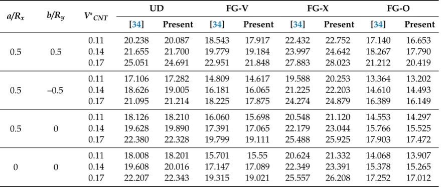
To verify the reliability and accuracy of the present model, several comparison studies were carried out with the results of the previous literature [34,35].
Example 1: Free Vibration of the Simply Supported Doubly Curved FG-CNTRC Panels
in Table1. From the results presented in Table2, it is observed that the values of the fundamental frequency for plates, spherical, cylindrical, and hyperbolic paraboloid panels have excellent agreement with the available data.
Table 2.Comparison of the non-dimensional frequenciesω=ωa2/h p
ρm/Emof the simply supported doubly curved FG-CNTRC panels.
a/Rx b/Ry V∗CNT
UD FG-V FG-X FG-O
[34] Present [34] Present [34] Present [34] Present
0.5 0.5
0.11 20.238 20.087 18.543 17.917 22.432 22.752 17.140 16.653 0.14 21.655 21.700 19.779 19.184 23.997 24.642 18.267 17.790 0.17 25.051 24.691 22.951 21.848 27.883 28.023 21.212 20.419
0.5 –0.5
0.11 17.106 17.282 14.809 14.617 19.588 20.253 13.364 13.202 0.14 18.626 19.005 16.181 16.065 21.225 22.203 14.610 14.493 0.17 21.095 21.214 18.225 17.875 24.274 24.879 16.389 16.149
0.5 0
0.11 18.126 18.210 16.060 15.698 20.548 21.120 14.553 14.297 0.14 19.628 19.890 17.391 17.065 22.179 23.044 15.766 15.525 0.17 22.380 22.328 19.799 19.111 25.488 25.925 17.903 17.472
0 0
0.11 18.008 18.201 15.701 15.55 20.624 21.332 14.068 13.907 0.14 19.608 20.016 17.147 17.089 22.349 23.391 15.378 15.265 0.17 22.207 22.343 19.315 19.021 25.557 26.208 17.252 17.012
3.2. Parametric Studies
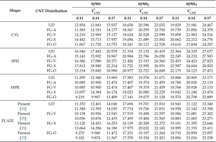
In this section, some new results for free vibration of the anti-symmetric cross-ply laminated FG-CNTRC doubly curved shell panels are investigated with respect to FG-CNTRC parameters, curvature,Rx/Ryratio, aspecta/bratio, and number of layers. The material properties for the matrix
and CNT are shown in Table1.
3.2.1. Effect of FG-CNTRC Parameters
To understand the effect of FG-CNTRC parameters on the free vibration response of different shell panels, non-dimensional frequenciesωof anti-symmetric cross-ply laminated FG-CNTRC doubly curved shell panels with different CNT distribution, CNT volume fraction, and number of CNT layers are examined.
Table 3. Non-dimensional frequenciesωof the simply supported FG-CNTRC doubly curved shell panels (a/b=1;R/a=5,a/h=50).
Shape CNT Distribution
(0/90) (0/90)2 (0/90)4
V*
CNT V*CNT V*CNT
0.11 0.14 0.17 0.11 0.14 0.17 0.11 0.14 0.17
CYL
UD 12.854 13.841 15.937 18.658 20.596 23.032 19.829 21.941 24.467 FG-A 11.383 12.181 14.177 18.367 20.295 22.700 19.739 21.856 24.378 FG-V 12.216 12.969 15.137 18.624 20.528 22.998 19.858 21.963 24.516 FG-X 14.442 15.713 17.937 19.084 21.089 23.582 20.062 22.212 24.776 FG-O 11.067 11.720 13.753 18.241 20.121 22.528 19.610 21.694 24.207
SPH
UD 16.540 17.442 20.579 21.334 23.132 26.419 22.364 24.335 27.677 FG-A 15.143 15.902 18.967 20.984 22.786 26.050 22.245 24.232 27.583 FG-V 16.366 17.080 20.371 21.426 23.193 26.560 22.453 24.423 27.823 FG-X 17.812 18.980 22.214 21.722 23.595 26.951 22.587 24.604 28.002 FG-O 15.214 15.845 18.990 20.977 22.723 26.008 22.175 24.123 27.472
HPR
UD 11.295 12.340 13.969 17.583 19.576 21.671 18.806 20.969 23.171 FG-A 10.085 10.900 12.474 17.407 19.374 21.459 18.768 20.928 23.133 FG-V 10.085 10.900 12.474 17.407 19.374 21.459 18.768 20.928 23.133 FG-X 13.057 14.384 16.174 18.023 20.080 22.229 19.042 21.240 23.474 FG-O 9.219 9.907 11.409 17.141 19.075 21.128 18.574 20.708 22.889
PLATE
Present UD 11.353 12.401 14.040 17.696 19.701 21.810 18.943 21.122 23.340 [35] 11.348 12.395 14.035 17.714 19.726 21.831 18.958 21.142 23.358 Present FG-V 10.138 10.956 12.541 17.519 19.498 21.597 18.906 21.081 23.302 [35] 10.056 10.876 12.435 17.495 19.484 21.565 18.883 21.065 23.271 Present FG-X 13.120 14.453 16.253 18.139 20.208 22.372 19.181 21.395 23.646 [35] 13.064 14.396 16.180 17.975 20.032 22.165 18.995 21.193 23.411 Present FG-O 9.270 9.960 11.472 17.251 19.197 21.264 18.710 20.859 23.057 [35] 9.182 9.874 11.367 17.378 19.354 21.421 18.856 21.036 23.238
3.2.2. Effect of Curvature
Two forms of doubly curved shell panels (SPH and HPR) witha/b=1,a/h=20,Rx=Ry=R,(0/90)5,
V∗CNT=0.17 were considered, to study the effect of curvature on the non-dimensional frequenciesω. The results are shown in the Figure3a,b. These figures indicate that at the small value ofR/a, the SHP panels have a much higher non-dimensional frequency than HPR panels. The non-dimensional frequencies of the SHP panels decrease, while those of HPR panels increase with the increase ofR/a ratio from one to a specific value. After this value, the non-dimensional frequencies of both SHP and HPR panels have approximate values and seem to be unchanged.
3.2.3. Effect of Curvature Ratio
The effect of curvature ratioRx/Ryon non-dimension frequency of the panels is investigated in
this subsection. The geometrical dimensions of the panels are taken asa/b=1,a/h=20,Rx/a=5. It can
be seen from Figure4a,b, that the non-dimension frequencies of panels decrease with the increase of curvature ratio from−3 to−1, and increase with the value of curvature ratio bigger than−1 for different numbers of layers and different CNT volume fractions. Moreover, the values ofωare at minimum whenRx/Ry=−1 shows that the curvature effect can be suppressed if the shell panels have
both negative and positive curvature.
Figure 4.Effect ofRx/Ryof FG-CNTRC shell panels (a/b=1,a/h=20,Rx/a=5, FG-X): (a) For different number of layers,VCNT∗ =0.17; (b) for different CNT volume fractions.
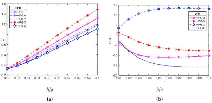
3.2.4. Effect of Thickness Ratio
The SPH shell panel was chosen to study the effect of thickness on the free vibration response of the FG-CNTRC doubly curved shell panel. For this purpose, another non-dimensional frequency is defined as [34]:
ˆ
ω=ωa
r ρm
Em (29)
PCF= ωˆFG−ωˆUD ˆ ωUD
!
×100 (30)
Figure 5. Effect ofh/aratio on free vibration of FG-CNTRC shell panels ((a/b=1; Rx =Ry = R;
VCNT∗ =0.17; (0/90)): (a) For the frequency parameter ˆω=ωa
q
ρm
Em; (b) for the (PCF).
3.2.5. Effect of Aspect Ratio
Figure6a,b show the effects of the aspect ratio (a/b) on the vibration of FG-CNTRC. Here, we take a/b=1;Rx=Ry=R;R/a=5;V∗CNT=0.17 and (0/90).
Figure 6.Effect of aspect ratio (a/b) on free vibration of FG-CNTRC shell panels (a/b=1;Rx=Ry=R;
V∗
CNT=0.17; (0/90)): (a) For the frequency parameter ˆω=ωa q
ρm
Em; (b) For the percentage change of frequency (PCF).
Figure6a reveals that the non-dimensional frequencies of all four types of doubly curved panels decrease uniformly by increasing aspect ratio. In other words, the stiffness of doubly curved panels will be reduced as the aspect ratio increases. Figure6a states that the PCF of the FG-CNTRC panels remains unchanged with the increase of aspect ratio.
3.2.6. Effect of Number of Layers
Figure 7.Effect of number of layers (n) on free vibration of FG-CNTRC shell panels (a/b=1,Rx=Ry=R;
VCNT∗ =0.17, (0/90)n: (a) For the frequency parameter ˆω=ωa
q
ρm
Em; (b) for the percentage change of frequencyPCF.
3.2.7. Effect of Different Wave Numbers
Table4listed non-dimensional frequencies for two-layered (0/90) FG-CNTRC doubly curved shell panels (a/b=1;R/a=5,a/h=50, FG-X,V∗CNT=0.17) for different wave numbers. It can be seen that at the small value of wave numbers (n,m) the SPH panels have highest non-dimensional frequencies while the HPR panels have lowest ones. However, it also can be seen that the non-dimensional frequencies of all three types of doubly curved panels will approximately have more wave numbers.
Table 4.Non-dimensional frequenciesωfor two-layered (0/90) FG-CNTRC doubly curved shell panels for different wave numbers (a/b=1;R/a=5,a/h=50, , FG-X,V∗CNT=0.17).
Shape n m=1 m=2 m=3 m=4 m=5 m=6
CYL
1 17.937 48.140 99.846 169.706 254.950 352.930
2 46.027 64.594 109.402 176.466 260.683 358.380
3 97.820 109.032 141.357 198.901 277.607 372.340
4 168.004 176.095 198.835 243.742 311.861 399.381
5 253.606 260.401 277.580 311.892 367.569 444.182
6 351.923 358.209 372.384 399.478 444.253 508.835
SPH
1 22.214 49.271 100.122 169.593 254.585 352.371
2 49.472 65.771 109.763 176.410 260.356 357.845
3 100.573 109.960 141.685 198.853 277.285 371.804
4 170.323 176.802 199.065 243.665 311.532 398.838
5 255.596 260.940 277.698 311.759 367.219 443.632
6 353.644 358.612 372.397 399.275 443.867 508.271
HPR
1 16.174 47.141 99.497 169.711 255.202 353.378
2 47.141 64.179 109.145 176.475 260.924 358.816
3 99.497 109.145 141.314 198.990 277.883 372.799
4 169.711 176.475 198.990 243.935 312.190 399.872
5 255.202 260.924 277.883 312.190 367.960 444.710
6 353.378 358.816 372.799 399.872 444.710 509.403
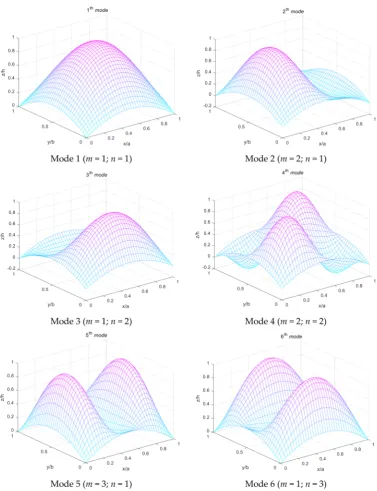
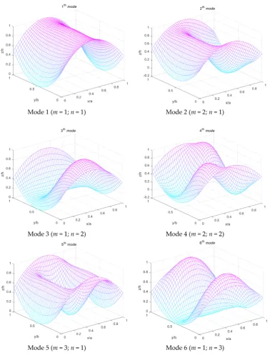
in bothxandydirections. These mode shapes can help to understand vibration characteristics of laminated FG-CNTRC doubly curved shell panels.
Figure 10.The first six mode shapes of simply supported laminated FG-CNTRC HPR panels.
4. Conclusions
The present theory is accurate and efficient in solving free vibration behaviours of doubly curved laminated FG-CNT reinforced composite panels and may be useful in the study of similar composite structures.
Author Contributions: Formal analysis, Software, V.V.T.; Writing-original draft, Investigation, T.H.Q.; Supervision-editing, T.M.T.
Funding:This research received no external funding.
Conflicts of Interest:The authors declared no potential conflicts of interest with respect to the research, authorship, and/or publication of this article.
Appendix A
Detailed steps to construct the new shape function:
The transverse strains associated with the displacement field in Equation (1) are:
γxz = 1+z1/Rx
h∂w
∂x+∂∂uz − u0
Rx
i
= 1+z1/R
x
h∂w
b
∂x +∂ ws
∂x + u0
Rx −
∂wb ∂x −f
0 (z)∂ws
∂x − u0
Rx
i
= 1+z1/R
x
h (1−f0
(z))∂ws
∂x
i
γyz = 1+z1/Ry
∂w ∂y+∂
v ∂z−
v0
Ry
= 1+z1/R
y
∂wb
∂y + ∂ws
∂y + v0
Ry −
∂wb
∂y −f
0 (z)∂ws
∂y − v0
Ry
= 1+z1/R
y
(1−f0
(z))∂ws
∂y
(A1)
For shells under bending, the transverse shear stressesσxz,σyzmust be vanished at the top and
bottom surfaces. These conditions lead to the requirement that the corresponding transverse strains on these surfaces have to be zero. Fromγxz
x,y,±h
2
=γyz
x,y,±h
2
=0, we obtain:
γxz= 1
1+z/Rx
" (1− f0
(z))∂ws ∂x
#
=0 at z=±h
2 (A2)
γyz= 1
1+z/Ry
" (1−f0
(z))∂ws ∂y
#
=0 at z=±h
2 (A3)
From Equations (A2) and (A3), we have:
f0(z)=1at z=±h
2 (A4)
Function f(z) satisfies the condition (5) can be selected as a polynomial, trigonometric, and exponential,. . . function. In our study, we chosef(z) as a cubic polynomial: f(z) =az+ b
h2z3, thus:
f0
(z) =a +3b h2z
2=1 (A5)
Some authors have chosen the value of the pair a, b to satisfy Equation (A5). In this study, we chose:a=−1/8,b=3/2. Thus:
f(z) =−1 8z+
3 2
z3 h2, f
0
(z) = −1 8 +
3.3 2
z2 h2
!
z=±h2 =1 (A6)
Appendix B
Matrix elements of Equation (25):
s11=− A11+2B11
Rx
+D11 R2
x
!
αm2− Aˆ66+2 ˆ B66
Rx
+Dˆ66 R2
x
!
s12=− A12+A66+ (B12+B66) 1 Rx + 1 Ry ! + 1
RxRy(D12
+D66)
!
βnαm (A8)
s14=
Bs11+D
s 11 Rx
αm3+
Bs12+Bs66+Bˆs66+D s 66 Rx + ˆ Ds 66 Rx + Ds 12 Rx
βn2+ARx11+ A12
Ry + B11
R2 x
+ B12 RxRy
αm (A9)
s22 =−
A66+2
B66
Ry
+D66 R2y
αm
2− ˆ A22+2
ˆ B22
Ry
+Dˆ22 R2y
βn
2 (A10)
s23=
A12
Rx +
ˆ
A22
Ry +
1
Ry
B12
Rx +
ˆ
B22
Ry
βn+
ˆ B22+
ˆ
D22
Ry
βn3+
B12+B66+B66+R1y
D12+D66+D66
βnαm2
(A11)
s24=
A12
Rx +
ˆ
A22
Ry +
1
Ry
B12
Rx +
ˆ
B22
Ry
βn+
ˆ Bs
22+ ˆ
Ds22 Ry
βn3+
Bs12+Bs66+Bs66+R1y
Ds12+Ds66+Ds66
βnαm2
(A12)
s33 =−AR112 x
−2 A12
RxRy − ˆ A22 R2 y −2 B12
Rx + ˆ
B22
Ry
βn2−2
B11
Rx + B12
Ry
αm2−
D11αm4−
2D12+2D66+D66+Dˆ66
αm2βn2−Dˆ22βn4
(A13)
s34=−AR112 x
−2 A12
RxRy − ˆ A22 R2 y − B11
Rx +
Bs11
Rx +
B12
Ry +
Bs 12
Ry
αm2−
B12
Rx + Bs
12
Rx +
ˆ
B22
Ry +
ˆ
Bs 22
Ry
βn2−
2Ds
12+2Ds66+D
s
66+Dˆs66
αm2βn2−D s
11αm4−Dˆs22βn4
(A14)
s13 =
A11
Rx +
A12
Ry +
1
Rx
B11
Rx +
B12
Ry
B12+B66+Bˆ66+R1x
D12+D66+Dˆ66
βn2
αm+
B11+DR11x
αm3
(A15)
s44=−AR112 x
−2 A12
RxRy
−Aˆ22
R2 y − ˆ As
44+2
Bs12 Rx +2
ˆ
Bs22 Ry
βn2−
As55+2B
s 11
Rx +2 Bs12
Ry
αm2−
2Es12+2Es66+Es66+Eˆs66
αm2βn2−E s
11αm4−Eˆs22βn4
(A16)
m11=−
I0+2RI1x + I2
R2x
;m12=0;m13 =
I1+RI2x
αm;m14 =
J1+ J2
Rx
αm;
m11=− I0+2RI1y +RI22 y
! ;m23 =
I1+RI2y
βn;m24 =
J1+
J2 Ry
βn;
m33=−I0−I2
αm2βn2
;m34 =−I0−I2
αm2βn2
;m44 =−I0−K1
αm2βn2
;
(A17)
References
1. Shen, H.-S. Nonlinear bending of functionally graded carbon nanotube-reinforced composite plates in thermal environments.Compos. Struct.2009,91, 9–19. [CrossRef]
2. Qatu, M.S. Theory and vibration analysis of laminated barrel thin shells. J. Vib. Control1999,5, 851–889. [CrossRef]
3. Reissner, E. A new derivation of the equations for the deformation of elastic shells.Am. J. Math.1941,63, 177–184. [CrossRef]
4. Bhimaraddi, A.; Stevens, L. A higher order theory for free vibration of orthotropic, homogeneous, and laminated rectangular plates.J. Appl. Mech.1984,51, 195. [CrossRef]
5. Eslami, M.; Shariyat, M. A high-order theory for dynamic buckling and postbuckling analysis of laminated cylindrical shells.J. Press. Vessel. Technol.1999,12, 94–102. [CrossRef]
6. Rahmani, O.; Khalili, S.; Thomsen, O.T. A high-order theory for the analysis of circular cylindrical composite sandwich shells with transversely compliant core subjected to external loads. Compos. Struct. 2012,94, 2129–2142. [CrossRef]
8. El Meiche, N.; Tounsi, A.; Ziane, N.; Mechab, I. A new hyperbolic shear deformation theory for buckling and vibration of functionally graded sandwich plate.Int. J. Mech. Sci.2011,53, 237–247. [CrossRef]
9. Thai, H.-T.; Vo, T.P. A new sinusoidal shear deformation theory for bending, buckling, and vibration of functionally graded plates.Appl. Math. Model.2013,37, 3269–3281. [CrossRef]
10. Thai, H.T.; Kim, S.E. A simple quasi-3D sinusoidal shear deformation theory for functionally graded plates.
Compos. Struct.2013,99, 172–180. [CrossRef]
11. Daouadji, T.H.; Tounsi, A. A new higher order shear deformation model for static behavior of functionally graded plates.Adv. Appl. Math. Mech.2013,5, 351–364. [CrossRef]
12. Mehrabadi, S.J.; Aragh, B.S. Stress analysis of functionally graded open cylindrical shell reinforced by agglomerated carbon nanotubes.Thin Walled Struct.2014,80, 130–141. [CrossRef]
13. Aragh, B.S.; Barati, A.N.; Hedayati, H. Eshelby–Mori–Tanaka approach for vibrational behavior of continuously graded carbon nanotube-reinforced cylindrical panels. Compos. Part B Eng. 2012, 43, 1943–1954. [CrossRef]
14. Yas, M.; Pourasghar, A.; Kamarian, S.; Heshmati, M. Three-dimensional free vibration analysis of functionally graded nanocomposite cylindrical panels reinforced by carbon nanotube. Mater. Des. 2013,49, 583–590. [CrossRef]
15. Alibeigloo, A. Free vibration analysis of functionally graded carbon nanotube-reinforced composite cylindrical panel embedded in piezoelectric layers by using theory of elasticity.Eur. J. Mech. A/Solids2014,44, 104–115. [CrossRef]
16. Lei, Z.; Zhang, L.; Liew, K.; Yu, J. Dynamic stability analysis of carbon nanotube-reinforced functionally graded cylindrical panels using the element-free kp-Ritz method. Compos. Struct. 2014, 113, 328–338. [CrossRef]
17. Moradi-Dastjerdi, R.; Foroutan, M.; Pourasghar, A. Dynamic analysis of functionally graded nanocomposite cylinders reinforced by carbon nanotube by a mesh-free method.Mater. Des.2013,44, 256–266. [CrossRef] 18. Shen, H.S.; Xiang, Y. Nonlinear vibration of nanotube-reinforced composite cylindrical panels resting on
elastic foundations in thermal environments.Compos. Struct.2014,111, 291–300. [CrossRef]
19. Shen, H.S.; Xiang, Y. Postbuckling of nanotube-reinforced composite cylindrical shells under combined axial and radial mechanical loads in thermal environment.Compos. Part B Eng.2013,52, 311–322. [CrossRef] 20. Shen, H.-S. Thermal buckling and postbuckling behavior of functionally graded carbon nanotube-reinforced
composite cylindrical shells.Compos. Part B Eng.2012,43, 1030–1038. [CrossRef]
21. Shen, H.-S. Torsional postbuckling of nanotube-reinforced composite cylindrical shells in thermal environments.Compos. Struct.2014,116, 477–488. [CrossRef]
22. Liew, K.; Lei, Z.; Yu, J.; Zhang, L. Postbuckling of carbon nanotube-reinforced functionally graded cylindrical panels under axial compression using a meshless approach.Comput. Methods Appl. Mech. Eng.2014,268, 1–17. [CrossRef]
23. Lei, Z.; Zhang, L.; Liew, K. Parametric analysis of frequency of rotating laminated CNT reinforced functionally graded cylindrical panels.Compos. Part B Eng.2016,90, 251–266. [CrossRef]
24. Tornabene, F.; Fantuzzi, N.; Bacciocchi, M.; Viola, E. Effect of agglomeration on the natural frequencies of functionally graded carbon nanotube-reinforced laminated composite doubly-curved shells.Compos. Part B Eng.2016,89, 187–218. [CrossRef]
25. Thomas, B.; Roy, T. Vibration and damping analysis of functionally graded carbon nanotubes reinforced hybrid composite shell structures.J. Vib. Control2017,23, 1711–1738. [CrossRef]
26. Arani, A.G.; Kiani, F.; Afshari, H. Free and forced vibration analysis of laminated functionally graded CNT-reinforced composite cylindrical panels.J. Sandw. Struct. Mater.2019, 1099636219830787. [CrossRef] 27. Lei, Z.; Zhang, L.; Liew, K. Analysis of laminated CNT reinforced functionally graded plates using the
element-free kp-Ritz method.Compos. Part B Eng.2016,84, 211–221. [CrossRef]
28. Thai, H.T.; Kim, S.E. A simple higher-order shear deformation theory for bending and free vibration analysis of functionally graded plates.Compos. Struct.2013,96, 165–173. [CrossRef]
29. Huu Quoc, T.; Minh Tu, T.; Van Tham, V. Free vibration analysis of smart laminated functionally graded CNT reinforced composite plates via new four-variable refined plate theory.Materials2019,12, 3675. [CrossRef] 30. Qatu, M.S.Vibration of Laminated Shells and Plates; Elsevier: Amsterdam, The Netherlands, 2004.
32. Reddy, J.N.Energy Principles and Variational Methods in Applied Mechanics; John Wiley & Sons: Hoboken, NJ, USA, 2017.
33. Wang, Q.; Shao, D.; Qin, B. A simple first-order shear deformation shell theory for vibration analysis of composite laminated open cylindrical shells with general boundary conditions.Compos. Struct.2018,184, 211–232. [CrossRef]
34. Pouresmaeeli, S.; Fazelzadeh, S. Frequency analysis of doubly curved functionally graded carbon nanotube-reinforced composite panels.Acta Mech.2016,227, 2765–2794. [CrossRef]
35. Huang, B.; Guo, Y.; Wang, J.; Du, J.; Qian, Z.; Ma, T.; Yi, L. Bending and free vibration analyses of antisymmetrically laminated carbon nanotube-reinforced functionally graded plates.J. Compos. Mater.2017, 51, 3111–3125. [CrossRef]