Olawale et al. World Journal of Engineering Research and Technology
UNDERGROUND CABLE FAULT DISTANCE DETECTOR USING
ATMEGA328 MICROCONTROLLER
K. Chaitanya Kishore*1, Muli Dheeraj Reddy1, Ananth Upadaya2 and T. Y. Satheesha3
1
Student VIIIth Semester. of ECE, NCET, Bangalore, India.
2
Asistant Professor, Dept. of ECE, NCET, Bangalore, India.
3
Associate Professor and Head, Dept. of ECE, NCET, Bangalore, India.
Article Received on 27/02/2019 Article Revised on 17/03/2019 Article Accepted on 08/04/2019
ABSTRACT
The basic principle of Electromagnetic theory is used to detect discontinuity in the cables laid below the ground. This is used for many applications. Companies prefer laying the cables underground because the climatic adversities don’t affect this. With advantages
come challenges. There are many difficulties in laying the cables and once laid in case of any complaints, it is difficult and costly to fix it. A solution has been employed in this project where the robot that is designed in this project is capable of finding where the complaint lies, so that the engineer can directly get the exact location of fault with the help of GPS and notification on respective mobile with the help of GSM technology.
KEYWORDS: Undergroung Cable Fault Distance Detector Using Atmega 328 Microcontorller.
INTRODUCTION
Defect in its electrical circuit takes place due to the current is diverted from the certain intended path and a fault occurs due to this. Faults are generally occurring due to mechanical failure, accidents, excessive internal and external stresses etc. When a fault occurs the power flow gets diverted due to this and supply of neighbouring zone gets affected voltages become unbalanced. Thus, it is of utmost important to detect the fault sooner. In last decade cables were made for overhead laying and currently underground cables are used because of
wjert, 2019, Vol. 5, Issue 3, 140-147.
World Journal of Engineering Research and Technology
WJERT
www.wjert.org
ISSN 2454-695X
Review Article
SJIF Impact Factor: 5.218
*Corresponding Author
K. Chaitanya Kishore
Olawale et al. World Journal of Engineering Research and Technology
superiority. The biggest advantage is that they are not affected by adverse weather conditions. Neither hot sunny day nor the rain influences it. But its biggest drawback is to locate the breakage of cable due to any reason. Currently approximate locations are found and the cables are dug out from location and checked manually to find exact point of discontinuity. Cable maintenance practices are of two categories: unplanned maintenance or planned maintenance. Unplanned maintenance is caused due to a power outage. Planned maintenance is a time to time inspection of power cables. Planned maintenance delivers reliable services, but it is not economical. Premature replacement of cables leads to economic losses, which can be avoided by replacing decision based on the specific site data rather than on generic estimates. The cable inspection is a very costly process. A broad spectrum of sensing is used for the inspection of cables. Some of these sensing methods are like acoustic detection, are greatly enhanced by the ability to make measurements along the cable, as opposed to relying on measuring parameters at the ends of the cables. The goal of this project is to develop an autonomous robotic platform that can inspect underground power distribution cables, thus providing utilities with accurate information regularly and at a lower cost. Currently developed robot can be used to locate break from an external point. When an underground cable is broken or short circuited then our robot will work over it and locate the exact point of discontinuity
Design of Robot
Olawale et al. World Journal of Engineering Research and Technology
Fig. 2: Prototype of the robot.
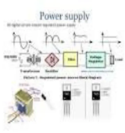
Power Supply – We are using linear regulated power supply having 5V output which will be useful for driving the other components in the circuit like microcontroller, gsm module and GPS module.
Fig. 4: Power Supply.[1,2]
Olawale et al. World Journal of Engineering Research and Technology
clock it. The output obtained at pin 11 of CD4017 drives the LED. Flashing of the LED (LED2) indicates the presence of mains, while LED1 indicates that the scanner is active.
3. Bluetooth- hc05 - this module is used to drive the robotic from one place to another place through the apps fom the cell phone.
4. Current Sensor: current sensing circuit is used to detect the cable fault.
5. Brushless Dc Motor - The BLDC motor is widely used in applications including appliances, automotive, aerospace, consumer, medical, automated industrial equipment and instrumentation. The BLDC motor is electrically commutated by power switches instead of brushes. Compared with a brushed DC motor or an induction motor, the BLDC motor has many advantages.
6. Microcontroller-ATmega328 - Arduino Uno microcontroller board based on the ATmega328.It is Open-source hardware, open source software. Boards are available commercially in preassembled form. Large number of PWM pins available. Pins can be configured as I/O and o/p as per requirement.
Fig. 4: Atmega328.[5]
Fig. 5: Pin Diagram of Atmega 328.[5]
Olawale et al. World Journal of Engineering Research and Technology
Fig. 5: LCD DISPLAY 16x2.[6]
8. GSM MODULE (SIM-900) - GSM/GPRS RS232 Modem from rhydoLABZ is built with S IMCOM Make SIM900 Quad-band GSM/GPRS engine, works on frequencies 850 MHz, 900 MHz, 1800 MHz and 1900 MHz it is very compact in size and easy to use as plug in GSM Modem. The baud rate can be configurable from 9600-115200 through AT command. Initially Modem is in Auto baud mode. This GSM/GPRS RS232 Modem is having internal TCP/IP stack to enable you to connect with internet via GPRS. It is suitable for SMS as well as DATA transfer application in M2M interface.
Fig: GSMSim900.[8}
9. GPS MODULE - The GXB5005 is a 12-channel GPS (Global Positioning System) receiver module. This small module includes all the functions required for GPS and is designed for using an active antenna. The GXB5005 can support the various kinds of the portable applications as well as the car navigation system.
2.Algorithm of System 1. Start.
2. Power is given to the circuit.
Olawale et al. World Journal of Engineering Research and Technology
4. Blue tooth gives signal to motor driver and Robot moves in respective direction.
5. Live Wire Scanner will detect the discontinuity in the cable.
6. If there is no discontinuity, then Robot will move in the respective direction.
7. Message will be sent through SMS on respective mobile phone by GSM. difference
exceeds a certain threshold.
3. Experimental Testing
Underground Cable Fault Detection Using Robot Currently designed robot can be used to locate fault in underground cable system. When an underground cable is broken or short circuited then our robot will work over it and locate the exact point of discontinuity. This robot works on the principle of electromagnetic theory. We can directly get the exact location of fault with the help of GPS and notification of fault location on respective mobile with the
help of GSM technology.[2]
Location of Fault
Pre-fault Voltage, Vref
(in Volts)
Voltage drop Measured, Vd
(in Volts)
Current flowing Through fault location, If (in µA)
Calculated Digital ADC Data for Microcontroller:
(Vd x 1024)/Vref
At 1 Km 5 2.50 250 512
At 2 kms 5 3.33 167 682
At 3 kms 5 3.75 125 768
At 4 kms 5 4.00 100 819
Olawale et al. World Journal of Engineering Research and Technology
5. CONCLUSION
The aim of the project is realized by testing the inspection of a mobile robot in a virtual environment conducive in producing real time operating atmosphere of an underground cable which can accurately spot the fault point and can report the coordinates of the fault point, which is novel attempt by using a GPS tracker. 2. Current scenario of digging along the cable laid and then pulling the cable out and checking whether the fault exists in the cables is a tedious work. This is not only being wastage of manpower and money for the companies, but this also causes a lot of inconvenience to the normal public. We believe that our cable fault detection robot will solve this issue to a great extent and will be really helpful for such application. The robot that we have designed is very much user friendly and can be easily controlled.
REFERENCES
1. Merugumalla Manoj kumar, Pasumarthi Vishnuvardhan, Pudota Ignatius Sirisha,
“Robotic Cable Inspection System Using Microcontroller and GPS Tracker”,
International Journal of Advanced Research in Electrical, Electronics and Instrumentation Engineering, March 2014; 3(3).
2. Jery Althaf, Muhammad Imthiaz, Rejith Raj, “Underground Cable Fault Detection using
Robot”, International Journal of Electrical and Computer Engineering (IJECE), April
2013; 3(2).
3. Miss Nikam Radhika R, Miss Tandale Swapnali S, Prof. Talewad Gururaj, interfacing”,
International Journal of Civil, Mechanical and Energy Science (IJCMES), 2016; 2(2).
4. Bing Jiang, Alanson P. Sample, Ryan M. Wistor, Alexander V. Mamishev, “Autonomous
Robotic Monitoring of Underground Cable Systems”, IEEE, December 2005; 4.
5. M.-S. Choi, D.-S. Lee, and X. Yang, “A line to ground fault location algorithm for underground cable system,” KIEE Trans Power Eng., 7148 ISSN: 2347-1697
International Journal of Informative & Futuristic Research (IJIFR) Volume - 4, Issue -8, April 2017 Continuous 44th Edition, Page No.: 7141-7148 Vidya P. Kodgirwar, Pooja Gajanan Dharamkar, Ashutosh Dattatray Gawade, Sagar Rajnarayan Gupta:: Underground Cable Fault Detection Using Robot, Jun. 2005; 267–273.
6. E.C. Bascom and D.W. Von Dollen, “Computerized underground cable fault location
expertise,” in IEEE.
7. Power Engineering Society Transmission and Distribution Conference, April 1994;
Olawale et al. World Journal of Engineering Research and Technology
8. Charles A. Maloney, "Locating Cable Faults", IEEE Transactions on Industry Applications, July-August 1973; IA-9(4).
9. F.S. Nickel, T.M. Salas, D.E. Thomas, and C.M. Wiggins, "Advanced Cable Fault Locator“, Final Report, EPRI EL-7451, October 1991, Electric Power Research Institute,
Palo Alto, California.
10.Dhivya Dharani. A, Sowmya T. Development of a Prototype Underground Cable Fault Detector, ISSN (Online): 2347-2820, 2014; 2(7).
11.Jiang B, Stuart P, Raymond M, Villa D, Mamishev A. V. “Robotic platform for
monitoring underground cable systems”. “Transmission and Distribution Conference and Exhibition Asia Pacific.” IEEE/PES Volume: 2 TO CITE THIS PAPER Kodgirwar P. V.,
![Fig. (1): Block diagram of underground cable fault detection.[1]](https://thumb-us.123doks.com/thumbv2/123dok_us/8362296.1671886/2.595.132.476.488.731/fig-block-diagram-underground-cable-fault-detection.webp)
![Fig. 4: Atmega328.[5]](https://thumb-us.123doks.com/thumbv2/123dok_us/8362296.1671886/4.595.148.444.384.696/fig-atmega.webp)
![Fig. 5: LCD DISPLAY 16x2.[6]](https://thumb-us.123doks.com/thumbv2/123dok_us/8362296.1671886/5.595.225.376.410.567/fig-lcd-display-x.webp)
