Volume-6 Issue-2
International Journal of Intellectual Advancements
and Research in Engineering Computations
ISSN:2348-2079
ABSTRACT
Current Solar Electric Vehicles have flat roofs, in an attempt to reduce irradiance mismatches within the strings of PV cells. As a result the aerodynamic performance and design freedom of such vehicles are limited. This paper presents a distributed maximum power point tracking methodology specifically aimed at Solar Electric Vehicles to overcome. As a starting point, the PV-to-isolated bus architecture is selected, since it processes a low amount of power and easily extends to an arbitrary number of groups per string. The collected electricity stored in a battery and used whenever need.
INTRODUCTION
PV array consisting of multiple strings of around 120 series connected PV cells. Can’t we use solar power at the night? This question may look somewhat absurd since there is obviously no meaning of “Using solar power
at night”! Now-a-days we are using the solar power to generate electricity by the solar panels mounted on the vehicle.
No clouds block the solar rays, and there is no nighttime. Solar collectors mounted on an orbiting satellite would thus generate power 24 hours per day, 365 days per year. If this power could be relayed to earth, then the world's energy problems might be solved forever. We propose a new method for power generation
A new control strategy for this architecture is introduced, that allows for local, decoupled, true maximum power point tracking. The architecture requires isolated, bidirectional, load independent converters, which were realized by means of a series connected synchronous boost converter.
Theoutcome of the solar tracker system has analyzed and compared with the fixed or static solar panel found better performance in terms of voltage, current and power. Therefore, the solar trackeris proved more practical for capturing the maximum C.Pratheeba1, K.Karthick2, K.S.Rajesh Kumar3, K.Rajkumar4,S.Vivek5
Professor1, Department of Electrical and Electronics Engineering, Nandha Engineering College, Erode, Tamil nadu, India
UG Student 2, 3, 4,5, Department of Electrical and Electronics Engineering, Nandha Engineering College, Erode, Tamil nadu, India
Portable solar lighting system
PORTABLE
SOLAR
LIGHTING
sunlight supply for star harvesting applications.
SOLAR TRACKER
A solar tracker is a perfect tool for track the path of the sun from east and west during daytime. For a conscientious line of longitude, every day sun moves from east to west on a fixed solar path. However, the sun moves through 460 degrees north and south throughout the seasonal revision. In our proposed model we have partiality to use micro controller based solar lighting system. The solar elevation approach is distinct for the reason that the angle located stuck between the horizontal and as a result the line linking to the sun. At nightfall or break of day distance from the ground approach is 0° and formerly the sun is at the pinnacle the height above sea level angle relics 90°.“Fig.
1,” shows the position of the sun over the year.
Fig. 1. The different position of the sun
over the year
EXPERIMENTAL SETUP
The proposed tracking system can track a lot of daylight in actual fact by PV panel rotation in different axis. we can achieve more energy from the solar panel. During this
emerge, we are able to incarcerate additional sun rays.
The portable solar lighting service is as good as to fixed panel however itcaptures the solar energy more productively by rotating within the horizontal as well because the vertical axis the likelyanticipated for dual axis tracker is shown in “Fig 2,”voltage & current sensors, 2 servo motors and Arduino microcontroller
consists our proposed system. One rest of sensors and onemotor is used to incline the tracker in sun’s east – west routeand the other rest of sensors and also the other motor that is mounted at the base of the tracker is used to tilt the trackerwithin the sun’s north-south route.
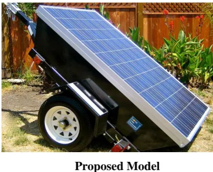
Proposed Model
Portable Solar Lighting system explained with the help of block diagram shown in “Fig. 3,”
The block diagram is showing that LDR sensors once sensingthe sunshine forward the signal to Microcontroller. Themicrocontroller is a logical device that’s enchanting dealings on the root of sensor put in and starting the motor driver’strack consequently.
Assume if the sun changes itsindividual locality and go from east to west, it’ll cause lightabsorption to vary on one sensor as related to differ-ent one. On the base of light intensity feature on sensors, thecontroller starts driver circuits and moves servo motor to newpositions wherever light falling on sensor pairs is same.
CIRCUIT DIAGRAM:
Components
Power supply
ARDUINO UNO
Microcontroller
Relay Circuit
DC-Motor
A) Power supply:
The Available power source is an Ac voltage arrives at 230V.Since our electronic circuits require only very minimal voltage and current we use step down power transformer. Step down transformer is designed in such a way that the input is 230V and output of 12V. Another thing is that electronic circuits operate in DC where as available output of transformer is Ac of 12V. So rectifier circuit is used to convert AC to DC. Rectifier circuit consists of four diodes formed in bridge fashion so as to convert incoming AC to DC.
B) ARDUINO UNO Microcontroller:
The Arduino Uno is a microcontroller board based on the ATmega328 (datasheet). It has 14 digital input/output pins (of which 6 can be used as PWM outputs), 6 analog inputs, a 16 MHz crystal oscillator, a USB connection, a power jack, an ICSP header, and a reset button. It contains everything needed to support the microcontroller; simply connect it to a computer with a USB cable or power it with a AC-to-DC adapter or battery to get started. The Uno differs from all preceding boards in that it does not use the FTDI USB-to-serial driver chip. Instead, it features the Atmega8U2 programmed as a USB-to-serial converter. "Uno" means one in Italian and is
BT1
BATTERY 12V/7.5AH C9
470UF/63V
PV Module U12
LM117 VIN 3 ADJ 1 VOUT 2 R1 2.2k 0 D1 DIODE
T1Current Sensor
1 5 4 8 D2 LED D3 LED D4 LED D5 LED D6 LED D7 LED D8 LED D9 LED D10 LED D11 LED D12 LED D13 LED D14 LED D15 LED D16 LED D17 LED D18 LED D19 LED LS1
RELAY SPDT
3 5 4 1 2 0 Q1 BC107 R2 1k R1 R1 D20 DIODE 0 U3 L293 1A 2 2A 7 3A 10 4A 15 1/2EN 1 3/4EN 9 1Y3 2Y6 3Y11 4Y 14 VCC1 16 VCC2 8 A -+ MG1 MOTOR DC 1 2 A -+ MG2 MOTOR DC 1 2 M3 M2 M1 +5 VCC M4 +12 VCC 22PF 0 +5 Vcc 16 m hz 6 10 K4 16 14 11 16 /2 LCD
named to mark the upcoming release of Arduino 1.0. The Uno and version 1.0 will be the reference versions of Arduino, moving forward. The Uno is the latest in a series of USB Arduino boards.
C) Relay Circuit:
Relays are electrically controlled switches. In the usual type, a coil pulls in an armature when sufficient coil current flows. Many varieties are available including “latching” and “stepping” relays; the later provided the cornerstone for telephone switching stations, and they’re still popular in pinball machines. Relays are available for dc or ac excitation, and coil voltages from 5 volts up to 110 volts are common. “Mercury-wetted” are “reed” relays are intended for high-speed (~ 1ms) applications, and giant relays intended to switch thousands of amps are used by power companies. Many previous relay applications are now handled with Transistor or FET switches, and devices known, as solid-state relays are now available to handle ac switching applications. The primary uses of relays are in Remote switching and high-voltage (or high-current) switching. Because it is important to keep electronic circuits electrically isolated from the ac power line, relays are useful to switch ac power while keeping the control signals electrically isolated. The electrical relay offers a simple on / off switching action in response to a control signal. When a current flows through the coil of wire a magnetic field is produced. This pulls a movable arm, the armature, that forces the contacts to open are
close; usually there are two sets of contacts with one being opened and the other closed by the action. This perhaps an electric heater in a temperature controls system.
D) DC-Motor:
A electric motor, operation is based on simple electromagnetism. A current-carrying conductor generates a magnetic field; when this is then placed in an external magnetic field, it will experience a force proportional to the current in the conductor, and to the strength of the external magnetic field. As you are well aware of from playing with magnets as a kid, opposite (North and South) polarities attract, while like polarities (North and North, South and South) repel. The internal configuration of a DC motor is designed to harness the magnetic interaction between a current-carrying conductor and an external magnetic field to generate rotational motion.
CONTROL ALGORITHM:
The same method can maintain it up with a change in sun’s locality surrounded by the sky. As a result, this proposedmodel is able to capture supplementary sun rays and system’ssolar energy conversion capability is greatly superior.How control algorithm is performing gesture assessment andis that the key deciding constituent which shows it in
“Fig. 5,” When it collects data from LDR
This serviceable task isperformed using analogue to digital converter (ADC).Digitized signals are forwarded to Arduino microcontroller. After collecting digital signals, it decides relating to themovement direction and steep angle of servo motors.Control algorithm is viewing that Arduino microcontrollerdrives servo motors as long as sensor light sensing is not equalto one another and if sensor signals are equal.It goes to start of the algorithm. This methodology is incessanttill light falling on detector pairs is equal and PV panel isadjusted in a position for optimum power.
The voltagegenerated by the solar panel is assorted and desires to be synchronized. A regulator is often used when the solarpanel which may regulate the voltage coming back from solar panel. For this principle, supply is provided by generated solar energy.
There is not any would like to give exteriorpower supply that makes our system economical and cost effective too. The purposed model can also use as animpartial system by introducing battery storage and propersupervision of storage system. Battery storage iscontrolled by the thought of generated voltage. Chargingand discharging events for storage are electing the idea of generated voltage.
Control Algorithm
HARDWARE
IMPLEMENTATION
PV Panel
PV panel used for hardware accomplishment is 36-watts and it’s of mono crystalline type. Two servo motors of static magnet types are used. Servo motor moves in steps and is best suited for correct position control. PIC microcontroller is used for controlling purpose that is less complicated to use as compared to microcontroller ATMEL family. Details of PV Panel ratings, LDR sensors and servo motor ratings for our hardware design are enlisted in Table I.
TABLE I. COMPONENT
RATINGS
Component Name Component Ratings
PV Panel Dimension 16×16 inches square PV Panel Rating 35 Watts PV Panel Material Mono crystalline
Servo Motor 5v, 0.6 A, 9gr Servo HXT900
Controller Arduino Uno
Component Ratings
CHARGE CONTROLLER
A charge controller, or charge regulator isfundamentally a voltage and current regulator to stay batteries from
overcharging. It regulates the voltage and current from the solar panels reaching to the battery. It prevents overcharging and will shield against overvoltage, which might scale back battery performance or period of time, and will create a safety risk. It is going to additionally prevent fully draining (“deep discharging”) a battery, or perform controlled discharges, counting on the battery technology, to guard battery life.
The charge controller is located in between the output of the solar battery and therefore the input of the battery holder. Once the intensity of daylight is high then solar battery produces more electricity, and once daylight is a smaller amount then produces less electricity. The charge controller is used to calming the variation in electrical input to the battery. It furthermore prevents over charging of the battery thereby increasing its life. A superfluous function of the charge controller is to stop reverse current flow, predominantly during night times.
CONCLUSIONS
energy by about 40% of the fixed arrays. Witha lot of works and higher systems, we tend to believe that this figure can raise more.
REFERENCES
[1] Bank, Grameen. “Grameenhakti: pioneering and expanding greenenergy revolution to rural Bangladesh.” (2007).
[2] Afrin, Farhana, TwishaTitirsha, SyedaSanjidah, A. R. M. Siddique, and
AsifRabbani. “Installing dual axis solar tracker on rooftop to meet the
soaring demand of energy for developing countries.” In IndiaConference (INDICON), 2013 Annual IEEE, pp. 1 -5.IEEE, 2013.
[3] “Journal on: Technical apprasial of solar home systems in Bangladesh: A field investigation Shahriar Ahmed ChowdhuryRenewavle energy", vol. 36, no. 2, pp. 77, feb 2011.
[4] F. Muhammad-Sukki, S. H. Abu-Bakar, R. Ramirez-Iniguez, S. G. McMeekin, B. G. Stewart, N. Sarmah, T. K. Mallick, A. B. Munir, S.H. Mohd, R. Abdul Rahim, "Mirror symmetrical dielectric totally internally reflecting concentrator for building integrated photovoltaic systems", Appl. Energy, vol. 113, pp. 32-40, 2013.