© Universiti Tun Hussein Onn Malaysia Publisher’s Office
IJIE
Journal homepage: http://penerbit.uthm.edu.my/ojs/index.php/ijie
The International
Journal of
Integrated
Engineering
ISSN : 2229-838X e-ISSN : 2600-7916
Kapton Based Antenna Simulation Analysis for Smart System
AH Dahalan
1*, MZAA Aziz
1, M.A. Othman
1, H Nornikman
1, S. Ibrahim
1Faculty of Engineering Technoloy & Faculty of Electronics and Computer Engineering,
Universiti Teknikal Malaysia Melaka, Hang Tuah Jaya, 76100 Durian Tunggal, Melaka, MALAYSIA
2School of Computer and Communication Engineering, Universiti Malaysia Perlis, Arau, 02600, Perlis, MALAYSIA
*Corresponding Author
DOI: https://doi.org/10.30880/ijie.2019.11.04.033
Received 8 August 2019; Accepted 26 August 2019; Available online 5 September 2019
1. Introduction
The conductive material used as a microstrip patch antenna design is copper (FR4), annealed copper, silver and Kapton. Copper is the most popular conductive material for low cost patch antenna type. While Kapton is more flexible and able to operate within a large temperature range (-73oC to +400oC). Kapton is passive circuits for microwave frequencies [1] and strain sensors [2]. The dielectric of Kapton depends on the temperature of the environment.
Kapton material is normally applied to a direct antenna designed according to the frequency and application of the antenna. The other applications is for flexible printed circuits (flexible electronics) and thermal blankets used for spacecraft, satellites and various space instruments. Previous work on smart antenna design techniques were proposed such as RF switching [3][4][5], Micro-Electro-Mechanical Systems (MEMS) [6][7] and algorithm[8][9] and etc. The switching technique is a neural network based switched beam smart antenna related to the azimuth and elevation angle of the radiation pattern for different base station antenna arrays covering of an area [3]. The beam switching technique is also used for WLAN adaptive array antenna to obtain phase shifting. The beam desired direction can be directed to avoid interference and the reduce power wastage of unused beams [4].
The MEMS technique uses radio frequency elements such as capacitor and inductor to design resonant frequency tuning capability through the construction of a tunable antenna [6]. Smart radar application where the beam steering array is designed with a coaxial probe technique in radiating element with different beam and increase the antenna gain also uses MEMS [7].
The algorithm technique such as LMS (least mean square) and the SMI (sample matrix inversion) was designed to reduce interference rejection problem with occurs in adaptive antenna[8]. The beam forming Hybrid Taguchi- genetic algorithm was designed to reduce interference with controlling side lobe levels in the desired of direction [9]. The
Abstract: This paper describes the analysis of Kapton material in antenna design for telecommunication systems. Kapton is usually used in the design of radio and microwave frequency antenna. It is a flexible material and with different dielectric( ) value. The antenna is made of a Kapton substrate, a patch and copper (FR4). The dielectric characteristics of Kapton substrate changes according to temperature. The simulation result shows that the bandwidth of the antenna increased up to 10 MHz with a second layer of Kapton substrate. While the antenna gain decreased 1.19 dB when the dielectric value is increased. Computer Simulation Technology (CST) software was used to analyse the antenna’s performance.
Hence, increasing the system’s capacity and power efficiency[10]. The main objective in antenna design is to improve the quality of signal for radio transmission. Another aspect that is worth exploring is visibility of the materials for smart antenna system.
This paper describes the Kapton material characteristic on microstrip patch antenna including several basic geometry shapes of Kapton. The analysis was carried out using Computer Simulation Technology (CST) software.
2.
Antenna Design
2.1
Description of Antenna Design
Microstrip patch antenna design using CST software at frequency 2.4 GHz is presented in this section. They are two materials have been used in this design work which are FR4 and Kapton. The FR4 material is practiced as the dielectric for the basic microstrip patch antenna. While, the Kapton material will be added on top of the microstrip patch antenna with different shape such as rectangular, circle, ring, triangular and etc. The basic parameter setup for antenna design as shown in Table 1.
Table 1 - Parameter setup.
Parameter Value
Frequency 2.4 GHz
Dielectric (εr ) 4.4
Height of Dielectric 1.6 mm Height of Kapton 0.055 mm
2.2
Description of formula Design
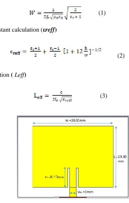
Fig. 1 shows the basic design of microstrip patch antenna. This antenna is designed based on the calculation of transmission model [11] as below;
i) Width (W) Calculation
(1)
ii) Effective dielectric constant calculation (εreff)
(2)
iii) Effective length calculation ( Leff)
(3)
Fig. 2 (a) shows the side view of the basic microstrip patch antenna (Design A). Then, the different shape of Kapton is added on top of the patch antenna as shown in Figure 2(b). The size of the Kapton is designed to have the same size as the patch.
(a) (b)
Fig. 2 - Microstrip patch antenna design (side view), (a) Design A – without kapton and (b) Design B to J with Kapton
3.
Simulation Result and Discussion
There are two analysis components of the study. First, the analysis of the dielectric changes on Kapton due to temperature. Second, is the analysis of the different shape of the Kapton. The size of the basic microstrip antenna has remained the same for both analyses.
3.1
Effect of Kapton Dielectric Permittivity
Kapton is a thin flexible polymide substrate where the material is the relative permittivity ( ) and loss tangent (tan
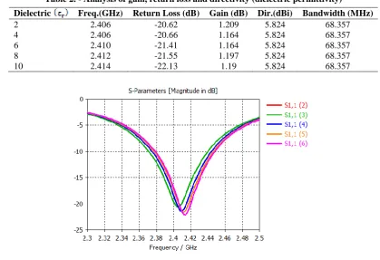
). The dielectric permittivity ( ) of Kapton changes according the temperature range (-73oC to +400oC). Thus, the performance of the antenna will also effect. The study was carried out using CST software. The permittivity of the Kapton was set from 0 to 10. The antenna parameter such as return loss, gain, directivity and radiation pattern were presented as below.
Table 2 shows the analysis of the return loss values, gain and directivity for the changes of dielectric permittivity values. The outcome indicates that the resonant frequency is shifted about 2 MHz to higher frequency when the dielectric permittivity value increases. There is no significant changes observed in gain and directivity. While, the return loss is reduced from -20.62 dB to -22.13 dB. Fig. 3 shows the return loss of the antenna.
Table 2. - Analysis of gain, return loss and directivity (dielectric permittivity)
Dielectric Freq.(GHz) Return Loss (dB) Gain (dB) Dir.(dBi) Bandwidth (MHz)
2 2.406 -20.62 1.209 5.824 68.357
4 2.406 -20.66 1.164 5.824 68.357
6 2.410 -21.41 1.164 5.824 68.357
8 2.412 -21.55 1.197 5.824 68.357
10 2.414 -22.13 1.19 5.824 68.357
Fig. 3 - Return loss analysis
(a) (b)
Fig. 4 - Radiation pattern, (a) Phi=0.0o and (b) Theta = 90o
3.2
Effect of Kapton Shapes
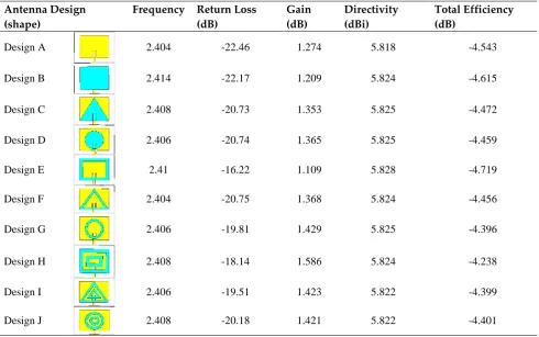
The analysis is performed by using CST software. First, the first analysis is the design without Kapton (Design A). Then, different Kapton geometry shapes were added on top of the patch (Design B to J). The reference output signal is taken from the value of maximum dielectric used in the Kapton shapes design in the simulation. The signal output result is shown in Table 3, Fig. 5 and Fig. 6.
Table 3 shows the analysis of the return loss values, gain, directivity and total efficiency for the changes of Kapton shapes design. The result shows that the resonant frequency is shifted about 2 MHz to higher frequency when the Kapton shapes. There are has a slight change in gain and directivity. From the simulation results, the gain in Design A (without Kapton) is 1.274 dB, while in Design B (with Kapton) the gain increased to 1.586 dB. The directivity value changed from 5.818 dBi to 5.828 dBi. While, the return loss is reducing from -18.14 dB to -22.46 dB and still working under -10dB. Fig. 5 shows the return loss of the antenna.
Table 2. - Analysis of gain, return loss and directivity (dielectric permittivity)
Antenna Design (shape)
Frequency Return Loss (dB)
Gain (dB)
Directivity (dBi)
Total Efficiency (dB)
Design A 2.404 -22.46 1.274 5.818 -4.543
Design B 2.414 -22.17 1.209 5.824 -4.615
Design C 2.408 -20.73 1.353 5.825 -4.472
Design D 2.406 -20.74 1.365 5.825 -4.459
Design E 2.41 -16.22 1.109 5.828 -4.719
Design F 2.404 -20.75 1.368 5.824 -4.456
Design G 2.406 -19.81 1.429 5.825 -4.396
Design H 2.408 -18.14 1.586 5.824 -4.238
Design I 2.406 -19.51 1.423 5.822 -4.399
Fig. 5 - Return loss analysis
Fig. 6 shows the radiation pattern analysis in 2D plane. There are significant changes in the horizontal plane. However, the vertical plane, the changes are more evident. The different shapes and sizes of the Kapton contributes to these changes. The half power beam width (HPBW) of the patch antenna seems changed between 200 to 600.
(a) (b)
Fig. 6 - Radiation pattern for realized gain, (a) Phi=0.0o and (b) Theta = 90o
Fig. 7 shows the current surface distribution at frequency 2.4 GHz and angle at 90o. Design A is without Kapton and design B to J with Kapton. The current flow occurred in surrounding the antenna from feedline to patch. The output simulation shows that when Kapton was applied together in the design, the current flows are stronger and covers all area despite being having different shapes and sizes. The higher concentration of current can be found when the rectangular Kapton was used. However, the surface current for Design C, D, F and G do not have much difference but the current flow still occurred surrounding the patch between -10.9 to -21.8 A/m.
Design A Design B Design C Design D Design E
Design F Design G Design H Design I Design J Strength Indicator
4.
Conclusion
In this paper, Kapton is material can apply together with antenna conductor such as FR4 to produce a new antenna design. From the simulation, the results shows that with different shapes Kapton can easily change the frequency when use different dielectric (εr) and also given a better performance for realized gain, directivity, return loss and radian pattern.
From the analysis, Kapton is found to be a material suitable for design antenna for the purpose of frequency change. Most of the parameter antenna design will be effected when apply together with an antenna. Due to Kapton’s characteristic which changes related to temperature, the dielectric can control by an electronic device to apply as smart antenna.
Acknowledgement
The authors would like to thank Universiti Teknikal Malaysia Melaka (UTeM) for supporting this research work under the grant PJP/2017/FKEKK/HI13/S01541. We also thank the Faculty of Electronics and Computer Engineering and Faculty of Engineering Technology at UTeM to support the research.
References
[1] Yang, Z., Takacs, A., Charlot, S. and Dragomirescu, D. Design of Kapton based passive circuits at microwave frequencies. Eur. Microw. Week 2015 “Freedom Through Microwaves”, EuMW 2015 - Conf. Proceedings; 2015
45th Eur. Microw. Conf. Proceedings, EuMC, (2015), pp. 873–876.
[2] Rufus, E. Microstrip antenna on kapton substrate for strain sensing applications. 16th Int. Conf. Adv Commun. Technol., (2014), pp. 453–455.
[3] Orakwue, S. I., Ngah, R., Rahman, T. A., and S. Z. Hashim, S. Z. M. Neural network based switch beam smart antenna. Proceedings, APWiMob 2014 IEEE Asia Pacific Conf. Wirel. Mob. 2014, (2014), pp. 292–296.
[4] Rahman, M. M., Dey, S. and Saha, N. Adaptive array antenna for WLAN: A smart approach to beam switching through phase shifting in feed network. Proceeding 15th Int. Conf. Comput. Inf. Technol. ICCIT 2012, (2012), pp. 632–637.
[5] Madany, Y. M., Elkamchouchi, H. M. and Salama, A. A. Design and analysis of optimum miniaturized conformal smart antenna system using 1×8 switched Butler matrix for wireless applications. Microw. Millim. Wave Technol. (ICMMT), 2012 Int. Conf., Volume 1, (2012), pp. 1–4.
[6] Kim, T and Vietzorreck, L. Investigation of smart antennas using RF-MEMS based tunable CRLH-transmission lines. Proc. 2012 Int. Conf. Electromagn. Adv. Appl. ICEAA’12, Volume 1, (2012), pp. 266–267.
[7] Lago, H., Jamlos, M. F., Aziz, S. Z. and Rahman, N. A. A reconfigurable MEMS beam steering array (RMBSA) antenna for smart RADAR application. IEEE Symp. Wirel. Technol. Appl. ISWTA, (2014), pp. 96–99.
[8] Mubeen, S., Prasad, A. M. and Rani, A. J. Smart antennas by using LMS and SMI algorithms reduces interfernce.
International Conference on Electrical, Electronics, and Optimization Techniques (ICEEOT), Chennai, (2016), pp. 204-208.
[9] Rao, A. P. and Sarma, N. V. S. N. Hybrid evolutionary algorithm based beamforming for smart antenna system.
Int. J. Electron. Lett., Volume 1, (2013), No. 4, pp. 189–19. [10] Slawsky, B. R. An introduction to smart retailing, (2016), pp. 1–3.