_________
*Corresponding author’s e-mail:[email protected]
Optimisation Frequency Design of Eddy Current Testing
Elya Alias1, Fauziah Sulaiman1, Abu Bakar Abdul Rahman1
1Physics with Electronics Program, Faculty Science and Natural Resources, Universiti Malaysia Sabah
Jalan UMS, 88400 Kota Kinabalu.
The main objective of this paper is to present the results of optimal frequency of metals testing from self-fabricated eddy current instruments. The instrument consisted of amplifier circuit, function generator, power supply, dual sensor and multimeter. Brass, copper (Cu) and magnesium alloy (Mg Alloy) metals in 100mm X 100mm X 1.5mm dimension were chosen as the metal testing with identical artificial defect and were tested to find its optimal frequency. The input frequencies ranged between 250 kHz - 3.5 MHz and a dual sensor were designed and established to gather the output. The output signals of the voltage of testing from the dual sensor then compared to analyze the optimal of range frequency for the testing instrument. The result of this research showed that the nondestructive metal testing instrument of dual sensor by using eddy current method can be used to find different defects for brass, copper (Cu) and Magnesium Alloy (Mg Alloy). The optimal frequencies for brass was 2.90 MHz, copper was 2.95 MHz and magnesium alloy metal was 2.89 MHz.
Keywords: Non-destructive testing (NDT), eddy current technique, optimal frequency.
I. INTRODUCTION
Eddy current technique is an important electromagnetic non-destructive evaluation method that is widely used in many industries for detection of surface cracks and sub-surface damage in components made of metallic materials (Rocha et al. 2015). Although eddy current testing is one of the oldest non-destructive testing (NDT) methods, however this method started to reach its true potential
193 preparation is minimal and results are drawn immediately. Eddy current could be made by high frequency magnetic field. The magnetic field happens when high frequency alternating current enters primary or transmitter coil (Betta et al., 2015). In case there is continuous space inside the test material, the eddy current will be higher. The eddy current will be lower if there are no continuous space inside the test material (Zhou et al., 2015). This difference could be used to measure the continuity of the test material by using eddy current. In this method, the current in the coil that constitute the probe induces eddy currents in the test material based on the basic principle of electromagnetic induction (Dholu et al., 2017). When a crack interrupts the eddy current flow the result is change of the coil impedance, by measuring these impedance changes or by measuring a resultant magnetic field using a coil sensor it is possible to detect the cracks in the test material. In order to ensure the basic studies of NDT in eddy current testing strengthen, the non-destructive metal testing instrument by using eddy current method which consisted of 50 ohm ground function generator which can adjust the frequency is proposed for this research. Finally, this paper will summarize the output in the last section.
II. MATERIALS AND METHODS
A. Proposed Analysis and Design
To obtain optimum frequency by testing the imperfections along with Brass, Copper (Cu) and Magnesium Alloys (Mg Alloy) have
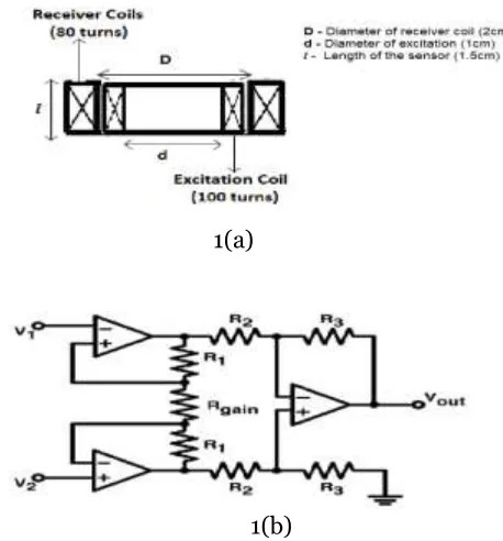
been tested for imperfections that cover the 1.5 mm thickness of the metal. In designing the metal testing instrument, the coil sensor need to design first. It is widely known that in order to improve the sensitivity of the coil should have large number of turns and large active area (Tumanski, 2007). In this research the turn number of coil of the sensor and the diameter of the sensor is emphasized with the total of 100 turns of excitation coils while receiver coil has 80 turns and diameter in 2 cm width. In this experiment two sensors has been used which are called as excitation and receiver coil (Pereira & Clarke, 2015).
1(a)
1(b)
Fig. 1 The excitation-receiver sensor (a). The schematic circuit of instrument amplifier (b).
194 dt dH A n dt dB A n dt d n
V . . . 0. . .
fundamental Faraday’s law of induction
(1)
where Φ is the magnetic flux passing through a coil with an area A and a number of turns n (Tumanski, 2007).Inductive coil will use an electrical load. Electrical current which runs through coil would induct because magnetic lines of force took place inside inductive coil (Mungkung et al., 2008). Output voltage drop for inductive coil from circuit could be calculated by the following equation:
(2)
When sensor is used to test imperfection of metal, it will be bring closer to metal. The inductance value of the coil would change. This change is due to various reasons like metal type, size of imperfection, distance and oscillator frequency (Dziczkowski et al., 2008). Thus, inductance value of sensor changed differently. The function generator is the most suitable for finding the optimisation frequency (Kushwah, 2012). The function generators are very versatile instruments as they are capable of producing a wide variety of waveform and frequencies (Tirmare, 2015). In order to make the design more accurate the instrument amplifier was designed. Instrumentation amps excel at extracting very weak signals from noisy environments. Thus they are often used in circuits that employ sensors that take measurements of physical parameters. It has high gain electronic voltage amplifier with differential input and, usually, a single-ended
output. The output voltage is many times higher than the voltage difference between input terminals (Mohd-Yasin, 2007). It has a specific role in circuits needing the advantages of high input impedance with good gain while providing common mode noise rejection and fully differential inputs. Fig.1(b) shows the schematic circuit of the instrument amplifier.
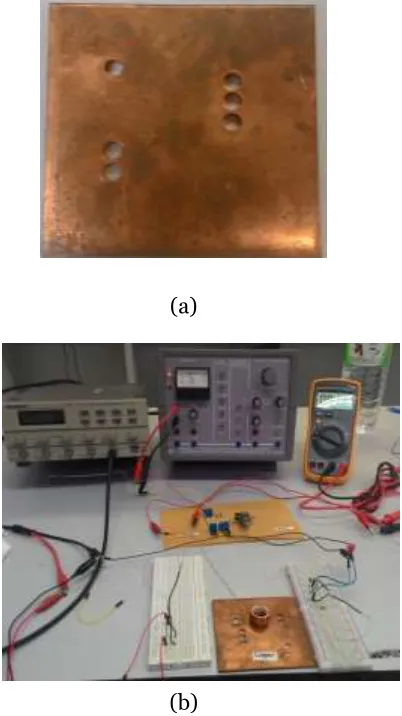
B. Experimental Setup
195
(a)
(b)
Fig. 2 The artificial defect on metal.(a) The testing instrument.(b)
III. RESULTS AND DISCUSSIONS
The results for imperfection of metal by using eddy current instrument to get the optimal frequency of brass, copper and magnesium alloy had been drilled with different of width on the surface (7, 14 and 21 mm). Mengbao Fan proposed that the suitable frequency range about 50kHz to 6MHz (Fan et al., 2016). For the self-fabricated eddy current instrument, the suitable frequency used was between 250 kHz–3.5 MHz and then the output voltage signals were plotted in a graph to compare
the differences of imperfection. The result for brass metal at Fig.3(a), from the graph shows that the optimal frequency for this metal testing is at 2.9 MHz. At 250 kHz to 1 MHz the output voltage reading was constant around 1V to 1.2V. Then at 1.25 MHz to 1.75 MHz the output reading decreases and then increases rapidly at 2 MHz until it reached the 2.90 MHz peak. After 3 MHz the reading is unstable and decreases rapidly. The result for copper metal at Fig.3(b), from the graph, 2.95 MHz shows the peak of output voltage reading that shows the optimal frequency. At 250 kHz to 2 MHz the reading of output voltage is up and down. After 2.95 MHz the reading sharply decreases and was found to be unstable. The results for magnesium alloy metal at Fig.3(c), from the graph 2.89MHz shows the peak of output voltage reading and shows that is the optimal frequency for magnesium alloy metal. At 250 kHz to 1.75 MHz the reading of output voltage was constant around 0.8V to 1.2V. After 1.75 MHz the readings rapidly increase until at 2.89 MHz. After 3.25 MHz the reading is unstable.
196
result of the imperfection testing was more accurate and stable.
3 (a) 3 (b)
3(c)
Fig.3(a) The output voltage imperfection of brass. Fig.3(b) The output voltage imperfection of (Cu). Fig.3(c) The output voltage imperfection of (Mg) alloy.
IV. CONCLUSIONS
This research has developed and established an optimal frequency for the three types of metal testing instrument (i.e., Brass, Cu and Mg) in strengthen the test of imperfection on metals by using frequency around 250 kHz to
3.5 MHz. It was found that the excitation frequency in brass is 2.90 MHz, copper metal is 2.95 MHz and in magnesium alloy is 2.89 MHz showed the most obvious differences and it was suitable for this kind of test. From this research it could be concluded that different types of metals have the different value of optimal
197 that it will contribute to an improvement of eddy current technique of metal testing and can be used in industrial inspection to avoid accidents and any misfortune.
V. ACKNOWLEDGMENT
This work was supported in part by UMSGreat Grant: GUG0018-SG-M1/2016. and SBK Grant:0280-SG-2016.
[1] Rocha, T.J., Ramos, H.G., Ribeiro, A.L., Pasadas, D.J. & Angani, C.S. (2015). Studies to optimize the probe response for velocity induced eddy current testing in aluminium. Measurement, 67, 108-115.
[2] Fan, M., Wang, Q., Cao, B., Ye, B., Sunny, A.I. & Tian, G. (2016). Frequency optimization for enhancement of surface defect classification using the eddy current technique. Sensors, 16,649.
[3] García-Martín, J., Gómez-Gil, J. & Vázquez-Sánchez, E. (2011). Non-destructive techniques based on eddy current testing. Sensors, 11, 2525-2565.
[4] Betta, G., Ferrigno, L., Laracca, M., Burrascano, P., Ricci, M. & Silipigni, G. (2015). An experimental comparison of multi-frequency and chirp excitations for eddy current testing on thin defects. Measurement, 63, 207-220.
[5] Zhou, H.T., Hou, K., Pan, H.L., Chen, J.J. & Wang, Q.M. (2015). Study on the optimization of eddy current testing coil and the defect detection sensitivity. Procedia Engineering,
130, 1649-1657.
[6] Dholu, N., Nagel, J.R., Cohrs, D. & Rajamani, R.K. (2017). Eddy current separation of nonferrous metals using a variable-frequency electromagnet. KONA Powder and Particle Journal, 34,241-247.
[7] Tumanski, S. (2007). Induction coil sensors—A review. Measurement Science and Technology, 18, p.R31.
[8] Pereira, D. and Clarke, T.G. (2015). current sensor for superficial and subsuperficial crack detection in inconel claddings. IEEE Sensors Journal, 15,1287-1292.
[9] Mungkung, N., Chomsuwan, K., Pimpru, N. & Yuji, T. (2008). Optimization frequency design of eddy current testing. WSEAS Transactions on Circuits and Systems, 7,213.
non-198 ferromagnetic metal plates. Archives of Materials Science and Engineering, 32, 77-84.
[11] Kushwah,R.S. (2012). Function Generator, viewed 12 December 2017 <http://ei-notes.
blogspot.my/2012/03/function-generator.html>.
[12] Tirmare, M.A.H. (2015). FPGA BASED FUNCTION GENERATOR.
[13] Mohd-Yasin, F., Yap, M.T. & Reaz, M.B. (2007). CMOS instrumentation amplifier with offset cancellation circuitry for biomedical application. WSEAS Transactions on Circuits and Systems, 6, 171-174.
[14] Fan, M., Wang, Q., Cao, B., Ye, B., Sunny, A.I. & Tian, G. (2016). Frequency optimization for enhancement of surface defect classification using the eddy current technique. Sensors, 16, 649.