• No results found

Hydraulic Disc Braking System of Electric Solar Car Mohammed Asif, Ramavath Suman, Md Azher Jaffer, Junaid Shareef, Mohammed Akram

N/A
N/A
Protected

Academic year: 2020

Share "Hydraulic Disc Braking System of Electric Solar Car Mohammed Asif, Ramavath Suman, Md Azher Jaffer, Junaid Shareef, Mohammed Akram"

Copied!
8
0
0

Loading.... (view fulltext now)

Full text

(1)

IJSRSET1732127 | 02 April 2017 | Accepted: 13 April 2017 | March-April-2017 [(2)2: 469-476]

© 2017 IJSRSET | Volume 3 | Issue 2 | Print ISSN: 2395-1990 | Online ISSN : 2394-4099 Themed Section: Engineering and Technology

469

Hydraulic Disc Braking System of Electric Solar Car

Mohammed Asif, Ramavath Suman, Md Azher Jaffer, Junaid Shareef, Mohammed Akram

Mechanical Department, Lords Institute of Engineering and Technology, Hyderabad, India

ABSTRACT

Electric Solar car is an electric vehicle powered completely or significantly by direct solar energy using the photovoltaic (PV) cells. The Analysis and understanding of Electrical and PV systems seems to be highly intuitive for fabrication of successful design of prototype. The main focus of our project is to design and analysis an effective braking system for electric solar car. A hydraulic disc brake system is design with three disc plates. Two plates are mounted in the front axle and one in the rear axle assisting to stop the vehicle instantly after applying the brake. Tandem master cylinder is used to apply hydraulic pressure which is transferred to the wheel units through two separate circuits. Report includes complete theory and procedure adopted for selecting the parameters, materials and designing of a brake system. Report is concluded with some Innovative ideas and future scope.

Keywords : Disc Brake, Master Cylinder, Calipers, Actuator, Spoiler.

I.

INTRODUCTION

Brake is a device by means of which artificial frictional resistance is applied to a moving machine member, in order to retard or stop the motion of the machine. Hydraulics is the use of a liquid under pressure to transfer force or motion, or to increase an applied force. The pressure on a liquid is called hydraulic pressure. The brakes which are operated by means of hydraulic pressure are called hydraulic brakes. These brakes are based on the principle of Pascal’s law.”

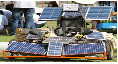
Figure 1: Final View of Electric Solar car

The pressure exerted anywhere in a mass of confined liquid is transmitted undiminished in all directions throughout the liquid”. Such as used in hydraulic lifts, hydraulic brakes, hydraulic actuators etc. In hydraulic disc brake, the fluid from the master cylinder is forced

into a calliper where it presses against a piston. The piston in turn squeezes two brake pads against the disc (rotor), which is attached to wheel, forcing it to slow down or stop the car.

Solar cars are beneficial to the environment as they don’t use fossil fuel there by the pollution caused by fossil fuel is absent but it also have limitations in speed and power of the car. When the sunlight strikes PV (Photovoltaic) cells which excite electrons and allows them to flow creating an electric current. The most commonly used is crystalline silicon

II.

METHODS AND MATERIAL

A. Objective

Our solar car consists of a mechanical brake that inhibits motion by absorbing energy from a moving system. The brakes are one of the most important components of the vehicle. They are required to stop the vehicle within the smallest possible distance and this is done by converting kinetic energy of vehicle into heat energy which is dissipated into the atmosphere.

(2)

master cylinder is used as master cylinder in our solar car because the tandem master cylinder transform applied brake force into hydraulic pressure which is transferred to the wheel units through two separate circuits.

B. Description

The world is facing too many problems running out of fuel and the exhaust from the vehicle is making ozone layer diminished. The one solution that will conserve fuel, save mother earth and ozone layer is solar powered cars.

In our solar car we used Brushless D.C motor which is a three-phase motor and it can run at a maximum speed of 2000 rpm. Solar panels of different sizes are used to meet the design requirements and to provide an overall sporty look. The three-phase motor cannot be directly connected so the need of controller is significant. For the car to run it needs a minimum of 48V and four Lead-Acid Batteries are used to power the car.

Rather than having only a single braking system, our solar car have been provided with an experimental braking system called as secondary braking which is possible with the help of an actuator and spoiler. The primary braking system plays major role as it provides brakes to all the three wheels of the car by following hydraulic principle. If in case, the driver is unable to stop the motion of vehicle by primary braking then he can use the secondary brakes provided at the rear tire. For this the driver has to press to the button which causes the movement of the actuator due to which the secondary master cylinder works and thus retard the motion of the car.

C. Hydraulic Brakes

Hydraulic Disc brakes consists of a cast iron disc bolted to the wheel hub and a stationary housing called calliper. The calliper is connected to some stationary part of the vehicle, like the axle casing or the stub axle and is cast into parts, each part containing a piston. In between each piston and the disc, there is a friction pad held in position by retaining pins, spring plates etc. Passages are drilled in the calliper for the fluid to enter or leave. These passages are also connected to another one for bleeding each cylinder contains a rubber sealing ring between the cylinder and the piston.

The brakes are applied, pressure is built in the cylinder and the lines as the brake pedal are depressed further. The pressure between the primary and secondary piston forces the secondary piston to compress the fluid in its circuit. If the brakes are operating properly, the pressure will be same in both the circuits.

Figure 2: Circuit Diagram of Hydraulic Disc Brake

System

The hydraulically actuated pistons move the friction pads into contact with the disc, applying equal and opposite forces on the disc. On realising the brakes the rubber sealing wings act as return springs and retract the piston and the friction pads away from the disc.

(3)

Components of Hydraulic Braking System

Solar car uses the hydraulically operated foot brakes on all the three wheels. The components of the system are listed below

 Brake lever or pedal. (pushes the master cylinder piston)

 Master cylinder. (produces pressure in the brake system)

 Hydraulic lines. (transfer hydraulic pressure from master cylinder to wheel cylinder)

 Disc or rotor

 Caliper unit.

 Mechanical linkage. (to move the caliper unit in radial direction)

D. Design of Disc Brake

Design Considerations

The design and fabrication of a hydraulic brake system of electric solar car requires some considerations. These include:

1. Feasibility / Viability: The design and fabrication of

the solar car because there are various machines/systems that have put into use the hydraulic brake system.

2. Cost: One of the objectives of this research is to design and fabricate a low-cost hydraulic brake system; hence the total cost of the project must be brought to a minimum to increase the chances of the product being highly marketable.

3. Maintainability: One of the primary objectives of this car is to simplify the diagnosis and maintenance of hydraulic brake systems; hence the car should be designed to receive no secondary maintenance.

4. Safety: It is to allow visibility to the users; they are constrained to enclosed sections to minimize accident. Non toxic and hazardous materials are used. Its fabrication and factor of safety will be highly emphasized in the design.

5. Ergonomics: The vehicle will be operated, hence the

size, shape, weight and materials used must suit the driver.

6. Wear and Noise: Moving parts introduces friction

and vibration which results in wear and noise. Friction and vibration should hence be controlled to the minimum.

Parameters for calculations

The Total weight of the vehicle =210 kg=2060.1 N The Speed of the solar car =50Kmph=13.88m/s2. The coefficient of friction between the tire and surface=0.7

The coefficient of friction between the pads and the rotor=0.4

Parameters

 Fbp= the force output of the brake pedal assembly

 Fd = the force applied to the pedal pad by the driver

 L1 = the distance from the brake pedal arm pivot to the output rod clevis attachment

 L2 = the distance from the brake pedal arm pivot to the brake pedal pad

 Pmc = the hydraulic pressure generated by the

master cylinder

 Amc = the effective area of the master cylinder

hydraulic piston

 Pcal = the hydraulic pressure transmitted to the calliper

 Fcal = the one-sided linear mechanical force

generated by the caliper

 Acal = the effective area of the calliper hydraulic

piston(s) found on one half of the calliper body

 Fclamp = the clamp force generated by the caliper  Ffriction = the frictional force generated by the

brake pads opposing the rotation of the rotor

 µbp = the coefficient of friction between the

brake pad and the rotor

 Tr = the torque generated by the rotor

 Reff = the effective radius (effective moment

arm) of the rotor (measured from the rotor centre of rotation to the centre of pressure of the caliper pistons)

 Tt = the torque found in the tire  Tw= the torque found in the wheel

 Ftire = the force reacted between the tire and the

(4)

 Rt,f = the effective rolling radius (moment arm)

of the loaded front tire=228.6 mm

 Rt,r = the effective rolling radius (moment arm)

of the loaded rear tire=304.8 mm

 Ftotal = the total braking force reacted between

the vehicle and the ground (assuming adequate traction exists)

 av = the deceleration of the vehicle  mv= the mass of the vehicle= 210 Kg  SDv = the stopping distance of the vehicle  Vv =velocity of moving vehicle =50 kmph

=13.88 .

 Vf = the front axle vertical force (weight)  Vr = the rear axle vertical force (weight)

 WT = the absolute weight transferred from the rear axle to the front axle

 g = the acceleration due to gravity (effectively expressing av in units of g’s)

 hCG = the vertical distance from the CG to

ground.

 Vf,d = the front axle dynamic vertical force for a

given deceleration

 Vr,d = the rear axle dynamic vertical force for a

given deceleration

 Ftires,f = the combined front tire braking forces  Ftires,r = the combined rear tire braking forces  µpeak,f = the maximum effective coefficient of

friction between the front tires and the road

 µpeak,r = the maximum effective coefficient of

friction between the rear tires and the road

TABLEI OBTAINEDVALUE Parameter Values Maximum Velocity 50 kmph

Pedal Effort 150 N

Coefficient of Friction between Road and Tire 0.7 Coefficient Of Friction Between Brake Pads And rotor

0.4

Wheel Rolling

Radius for Front and

Rear

0.2286 m & 0.3047 m

Brake Pedal Force

( )

Fbp= 150× (4/1) = 600 N

Master Cylinder Pressure

=12.96 mm

Pmc = *

+= 46.29 N/mm

2

Brake Fluid, Brake Pipes, and Hoses Pcal = Pmc

Caliper Force

Acal=30.75 mm

N Clamping Force Brake Pads Rotor Torque Tire Force The force of Front tires and the ground

The force of Rear tires and the ground

(5)

Stopping Distance

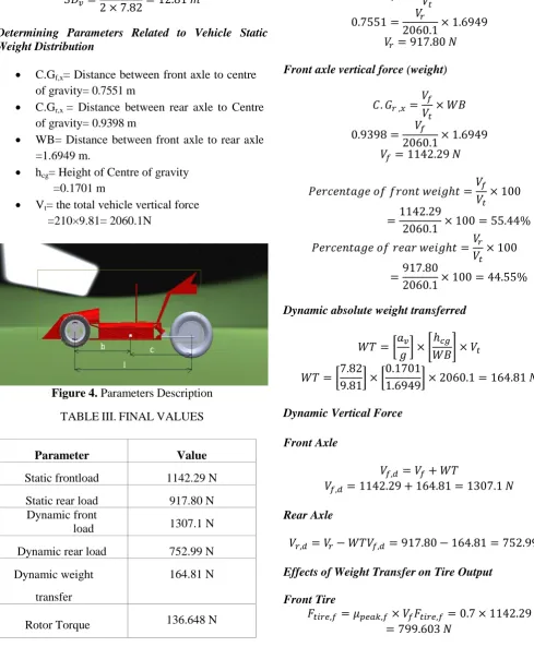
Determining Parameters Related to Vehicle Static Weight Distribution

 C.Gf,x= Distance between front axle to centre

of gravity= 0.7551 m

 C.Gr,x = Distance between rear axle to Centre

of gravity= 0.9398 m

 WB= Distance between front axle to rear axle =1.6949 m.

 hcg= Height of Centre of gravity

=0.1701 m

 Vt= the total vehicle vertical force

=210×9.81= 2060.1N

Figure 4. Parameters Description

TABLEIII.FINALVALUES

Parameter Value

Static frontload 1142.29 N

Static rear load 917.80 N

Dynamic front

load 1307.1 N

Dynamic rear load 752.99 N

Dynamic weight

transfer

164.81 N

Rotor Torque 136.648 N

Stopping

Distance 12.81m

Braking Efficiency

80.03%

Rear axle vertical force (weight)

Front axle vertical force (weight)

Dynamic absolute weight transferred

[ ] [

]

[

] [

]

Dynamic Vertical Force

Front Axle

Rear Axle

Effects of Weight Transfer on Tire Output

Front Tire

(6)

Rear Tire

Maximum Braking Force Produced By Axle

Front Axle

Rear Axle

Braking Efficiency

[

]

[

]

III.

RESULTS AND DISCUSSION

Innovation In Braking

Braking with Spoiler

The spoiler was first given by racing cars and sports and today, this add-can be spotted on all types of cars. While adding a spoiler to a vehicle certainly does add some unique style.

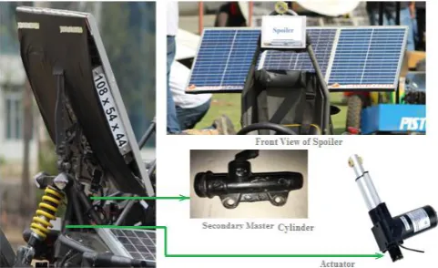
The main components responsible for this type of braking are

1. Spoiler or Pedestal Spoiler 2. Secondary Master Cylinder 3. Actuator

4. Electric Switch

Actuator

An actuator is an element which is responsible for moving or controlling a mechanism or system. It requires a control signal and a source of energy. The control signal is relatively low energy and may be electric voltage or current, pneumatic or hydraulic pressure, or even human power. When the control signal is received, the actuator responds by converting the energy into mechanical motion.

Spoiler

A spoiler is an automotive aerodynamic devices change the airflow going over the car to increase the downward pressure, essentially pushing the car down to counter the lift. Most are attached to the back of the vehicle, above the trunk, on the rear window, on the roof, or on the front. Various types and the positioning of a spoiler can do different things to improve a vehicle’s performance. However, the main reason people install these gadgets is to allow for better airflow over and around the vehicle, which in turn, creates better grip or traction on the road.

Working of Secondary Spoiler Brakes

Braking through spoiler follows the concept similar to that of mechanical braking system The secondary spoiler brakes act as lifesaving brakes if in case, the primary brakes fail the driver can operate secondary brake (braking through Pedestal spoiler) to stop the car. This can be achieved with the help of an electric switch. The switch operates the actuator present just below the spoiler which moves in linear motion. This motion causes the spoiler to change its angle which helps the solar panel present on it to attain maximum efficiency by absorbing more amount of solar energy. When the spoiler comes to extreme end which is of 90˚ inclination at this position the secondary master cylinder present below it comes into action as it gets pressed with the help

Figure 5: Innovation in Spoiler

(7)

city or suburbs under 70 mph may not see any immediate changes.

However, people who do serious highway driving can benefit most from adding spoilers.

Finally in Electric solar car pedestal spoiler is used as to give it an aerodynamic look and secondary braking which represents one of the innovations in electric solar car.

The Many Benefits of an Electric Car Spoiler

Installing a spoiler on a vehicle provides a variety of benefits for owners. The main benefits, perhaps, are for better traction and to add a sporty look, but also include other advantages, such as added visibility, reduced vehicle weight, and braking stability.

Benefit 1: Increase Braking Stability

Spoiler raise the downward force on the back of the vehicle not only increases traction, but the braking ability as well. Drivers have an easier time braking, even at high speeds, making driving even safer.

Benefit 2: Maintain Traction

The main benefit of installing a spoiler on a vehicle is to help it maintain traction at very high speeds. When a vehicle goes very fast, the air pressure can lift the car, which makes it difficult to manoeuvre the car without the danger of having it spin out of control. Rear spoilers, in particular, push the back of the car down so the tires can grip the road better and increase stability.

Benefit 3: Added Visibility

Another advantage of installing a rear spoiler on a vehicle is the added visibility, which means other drivers on the road can easily see the vehicle to help prevent rear-end collisions and other types of accidents.

Benefit 4: Reduce Weight

Believe it or not, a spoiler can reduce the weight of a vehicle. The only thing keeping a vehicle stable on the road is its weight. Perhaps that is why many people have this perception. However, having a spoiler means that the car manufacturer can reduce the weight of the vehicle by

using lighter materials or doing away with unnecessary weight without the worry that driving at high speeds causes the car to become unsteady and fly off the highway.

Benefit 5: Create a Stylish Look

Most car owners install spoilers as a fashion accessory, and spoilers do a pretty good job of making a vehicle look cool. Today, many cars come with built-in spoilers to evoke that sporty look, though many aftermarket spoilers are available for a wide variety of car makes and models

IV.

CONCLUSION

At the conclusion of this project, the measurement procedure proposed make it possible to calculate the dependence of the wheel braking forces on the force applied to the brake pedal or on the fluid pressure in the hydraulic braking system, within a range achievable in real braking conditions. In this research a comparatively study of theoretical and practical braking system is performed and finally brake system is assembled in electric solar car which is designed and fabricated to keep the drive in its comfort zone and ensures safety so that the driver can peacefully enjoy the ride of the car. The fabrication model was subjected to testing in lab and found effective in stopping the car.

Presented model has implemented some innovative parts such as spoiler for rear wheel braking and electrical switch in case of failure of primary braking system. The braking system further can be enhanced by using ABS as a safety factor in future works.

V.

REFERENCES

[1]. James Walker,"The Physics of Braking System", Jr scR Motorsports, Copyright 2005 StopTech LLC.

[2]. Dr. Kirpal Singh,"Automobile Engineering", Standard Publisher Distributor, 13th Edition 2013. [3]. Savio Pereira, Omkar Vaishampaya, Akshay

Joshi,"A Review on Design of Hydraulic Disc Brkaes and Calculations", PVG’s COET, Pune 411009, Vol 3, Issue 2, February 2014.

(8)

Journal of Research in Science and Technology, Vol 5, Issue 3, Jul-Sep.

[5]. Limpert Rudolf,"Brakes Design and Safety",Society of Automotive Engineers, Warrandale, Inc, 2nd Edition.

Figure

Figure 1:  Final View of Electric Solar car
Figure 2:  Circuit Diagram of Hydraulic Disc Brake System
Figure 4. Parameters Description
Figure 5: Innovation in Spoiler

References

Related documents

Risk Factors for the Development or Progression of Tractional Retinal Detachment following Intravitreal Bevacizumab (Avastin) in Patients with Severe Proliferative

The objective of this study was to explore flash flood forecasting by looking at a comparison of the experimental HRRRE and the operationally used HREF through

For the problematic areas, it should be found “ universal common law principles ” that give an absolute guarantee and compromise “ equity, justice and fairness ” and include a

Based on the graph, it show that when run the experiment with too deep depth which is 5mm and the feed rate and spindle speed was too slow, it will let chatter to occurred.. It

The obtained results from the tests confirms that the vortex shedding is not only affected by blockage ratio and sensor location but also by the after body shape

The independent variables were the nationality of the subjects, sex, number of foreign languages spoken, having been abroad and how long, and having received specific

The Fund may invest in underlying funds and may be indirectly exposed to currency risk, interest rate risk, other price risk and credit risk from fluctuations in the value of