Requirements-Level Language and Tools
for Capturing Software System Essence
Wiktor Nowakowski1, Michał ´Smiałek1, Albert Ambroziewicz12, and Tomasz
Straszak1
1
Warsaw University of Technology pl. Politechniki 1, 00-661 Warsaw, Poland
{nowakoww, smialek, ambrozia, straszat}@iem.pw.edu.pl 2 Infovide-Matrix S.A.
ul. Gottlieba Daimlera 2, 02-460 Warsaw, Poland
Abstract. Creation of an unambiguous requirements specification with precise domain vocabulary is crucial for capturing the essence of any software system, either when developing a new system or when recov-ering knowledge from a legacy one. Software specifications usually main-tain noun notions and include them in central vocabularies. Verb or ad-jective phrases are easily forgotten and their definitions buried inside im-precise paragraphs of text. This paper proposes a model-based language for comprehensive treatment of domain knowledge, expressed through constrained natural language phrases that are grouped by nouns and in-clude verbs, adjectives and prepositions. In this language, vocabularies can be formulated to describe behavioural characteristics of a given prob-lem domain. What is important, these characteristics can be linked from within other specifications similarly to a wiki. The application logic can be formulated through sequences of imperative subject-predicate sentences containing only links to the phrases in the vocabulary. The paper presents an advanced tooling framework to capture application logic specifications making them available for automated transformations down to code. The tools were validated through a controlled experiment.
Keywords:requirements engineering, use cases, domain engineering, model-driven software development, model transformation, application logic, metamodel, formal languages.
1.
Introduction and Related Work
we could transfer this essence (after possible improvement and extension) into a new technology.
An important attempt to enable capturing essential knowledge about soft-ware systems is the Knowledge Discovery Metamodel (KDM), as explained by P ´erez-Castillo et al. [29]. Unfortunately, KDM operates mainly at quite low levels of abstraction, concentrating e.g. on defining a metamodel for abstract syntax trees capturing the code structure of the system. It also contains structures to represent conceptual-level artifacts but this part of the standard is very roughly defined. Moreover, it can be argued that capturing the detailed internal structure does not reduce the accidental complexity associated with the “twisted” inter-nals of a legacy system. We need means to capture the essence of the system’s logic and not e.g. the detailed code breakdown structure as implemented in the legacy system.
An innovative method for improving software application comprehension in order to simplify its maintenance was proposed by Vagaˇc and Koll ´ar in [38] and [24]. In this approach a legacy system, composed of well-known classes and standard libraries, is analysed and a metamodel for the selected features repre-senting functional aspects of the system is automatically created. This provides feature-specific visualization which is closer to the application domain level than to implementation level. The main difficulty in this approach is associated with the construction of a knowledge base – for each recognized feature there must be aspects defined to trace feature implementation and algorithms to model traced implementation details in metamodel.
A very comprehensive approach to capturing essential knowledge (Domain Driven Development - DDD) was proposed by Evans [10]. He postulates organ-ising software development around rigorously defined domain models. These models capture the domain logic of the system at a high level of abstraction. At the same time, the domain logic is the foundational basis to specify the appli-cation logic describing the observable interaction of the users with the system (called “workflow logic” by Fowler [13]). This approach was even strengthened in rigour by Bj ˆorner [4] who advocates mathematical precision in domain engi-neering. He identifies serious flaws in system specification whenever domain specifications are treated without enough care.
The tooling for DDD has been developed in the context of the Romulus project (see work by Iglesias et al. [16]). However, the domain models in Ro-mulus are at the level of design models rather than pure domain descriptions. A domain-driven approach was also taken by the creators of the Requirements Specification Language (RSL, see section 2 for an overview of the language basic constructs) within the ReDSeeDS project (www.redseeds.eu). The do-main models in this language rely heavily on verbs used within requirements specifications. This is also similar to knowledge engineering approaches like the one described by Chan [7] and also pure ontology languages like RDF [1]. In effect, we result with a constrained language with embedded semantics, ca-pable of representing domains along the proposition by Evermann and Wand [11]. Moreover, the language introduces a very strict relation between the do-main logic (expressed through verbs associated with nouns) and the application logic.
In the current work we use RSL to enable capturing the essential complex-ity at the level of application logic of either existing or new systems (see sec-tion 2 for more details on this subject). This kind of “essential complexity” is meant as sequences of user-system, system-system and system-user interac-tions defining the observable system behavior. We propose to capture it through constrained-natural-language sentences that refer (hyperlink) directly to a do-main model based on nouns, verbs and other parts of speech. Similar usage of hyperlinks was proposed by Kaindl [20], but such a comprehensive treatment with an extensive tooling environment is not found in the literature according to our best knowledge. What is more, we propose a method for capturing and mi-grating the essence from legacy systems. It is unique in generating application logic scripts from UI/GUI-ripping results. The users record their activity in the legacy system and this is transferred to the application logic (essential) specifi-cation. Due to precision of such specifications, this can be brought to the level of code in an MDA-style transformation process [22].
This paper constitutes a significant extension to a paper published at the Model-Driven Approaches in System Development workshop at the FedCSIS conference [35]. It provides details on the slightly improved RSL metamodel and gives more examples. It also presents an advanced version of the tools both for recovery and transformation of application logic to code. There are also presented in detail the results of a controlled experiment to validate the presented approach and tools.
2.
Basic RSL Constructs for Specifying System Essence
Show course list Add new course course list button course list page «invoke» Course manager course list
1. Course managerselectscourse list button 2. Systemfetchescourse list
4. Systemshowscourse list page ==> invoke: Add new course
1. Course managerselectscourse list button 2. System fetchescourse list
3. Systemshowscourse list page => invoke: Add new course
course U se ca se s a n d s ce n a ri o s D o m a in sp e ci fi ca ti o n
Fig. 1.Example RSL specification – use case scenarios linking to a domain vocabulary
natural language. Words and phrases used in scenario sentences are linked to elements of a separate domain model, as presented in Figure 1.
Such notation, with a centrally defined vocabulary, is easily understandable by different audiences – analysts, developers, architects and end-users. The aim is to facilitate communication during the software development process. The main focus of this communication is usually the outlining of the application logic. The application logic of an IT system defines sequences of interactions between the user and the system in relation to the domain logic within which this system operates. That is the exact information that is captured at the level of requirements through the use of RSL (more on capturing the application logic can be found in section 2.6).
In addition to being human-readable, the RSL notation is also very precise. All the language constructs are defined in a formal way through a grammar ex-pressed as a MOF [27] metamodel. This allows automatic processing of speci-fications written in RSL (like, for example, MDA-style transformations [26]).
In sections below we describe basic RSL constructs in a bottom-up manner. Due to the extensiveness of the language, the description is limited only to the constructs that are used directly for capturing the software “essence” at the level of application logic. For the extended overview of the RSL language please refer to [34] and to [19] for the complete formal language definition.
2.1. Phrases – Basic Building Blocks for Specifications
enroll selected student for course
Noun phrase Noun phrase
Simple verb phrase
Complex verb phrase
Verb Modifier Noun Preposition Noun
enroll selected student for course
Fig. 2.Phrase structure example
strongly relevant to the noun: it describes behaviours, functions and events of the entity represented by that noun. These are important elements of domain descriptions as defined by Bj ˆorner [3]. One noun can have any number of be-haviours, functions or events associated (“read book”, “write book”, “buy book”). Sometimes there is a need to enrich nouns with modifiers (“single book”, “old book”).
To capture the application logic we will thus define a language capable of expressing noun-based phrases. This is illustrated in Figure 2. A noun phrase contains just a noun (“course”) possibly preceded by a modifier (“selected stu-dent”). A modifier is most often an adjective or an adverb. A simple verb phrase consists of a noun phrase preceded by a verb (“enroll selected student”). A complex verb phrase supplements a simple verb phrase with an additional noun phrase. These phrases are conjoined with a preposition, thus making a com-plex verb phrase capable of expressing constructs with a direct object and an indirect object (“enroll selected student for course”).
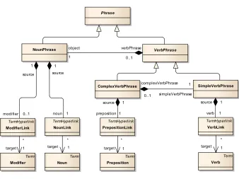
The above can be seen as a constrained language and we can define a grammar for it. We want the language to be used for automatic transformations and thus we will use a metamodel to define it (work by Kleppe [23] can be used as a good introduction on this). This is shown in Figure 3.
All phrases are represented by an abstract metaclassPhrase, which has two subtypes: NounPhrase and VerbPhrase. A NounPhrase consists of exactly one
NounLinkthat points to a specificNoun. ANounPhrasecan also contain at most
one ModifierLinkpointing to a Modifier. Such NounPhrasesare satisfactory for
representing entity names (eg. “course”, “selected student”). A VerbPhrase, in turn, describes some behaviour that can be performed in association with an entity represented by aNounPhrase. In the metamodel,VerbPhraseis an abstract subtype ofPhraseand it exists in two concrete variants:SimpleVerbPhraseand
ComplexVerbPhrase. TheSimpleVerbPhraseis the basic structure for expressing
VerbPhrase
NounPhrase
ComplexVerbPhrase SimpleVerbPhrase
Phrase
complexVerbPhrase
0..1 simpleVerbPhrase 1 object
1
verbPhrase 0..1
source 1
source 1
source 1 source 1
TermHyperlink
NounLink
TermHyperlink
VerbLink
Term
Noun
Term
Verb
Term
Modifier
Term
Preposition
TermHyperlink
ModifierLink
TermHyperlink
PrepositionLink
target 1 * target 1
* *
target 1 *
target 1
modifier 0..1 noun 1 preposition 1 verb 1
Fig. 3.Phrase metamodel
It is worth noting that the phrases constitute sequences of hyperlinks (sub-classes ofTermHyperlink) pointing at external terms (subclasses ofTerm– see Figure 4). These terms (with their forms, which depend on the context) can be stored in an external, global structure (Terminology). This structure defines the semantics of the terms through giving relations between them, and can be based on existing dictionaries/ontologies (e.g. WordNet [12]). This way, the phrases can be subject to semantic-based matching, as described by Wolter et al. [40].
2.2. Domain Specification – Phrases Grouped within Notions
To organise the phrases we will group them by the nouns defining the described domain entities. We will call such group a “notion”. The appropriate metamodel for this part of the presented language is shown in Figure 5. EveryNotioncan include any number ofDomainStatementsreferring to the same noun (eg. “save course”, “enroll student for course”). Each DomainStatement contains exactly
onePhrase– itsname. It can also have a textual description of behavioural
Termionology
Preposition Modifier
Noun Ve rb
Term
- na me : String *
1
Fig. 4.Terminology metamodel
DomainElement
NounPhrase
Notion
DomainElementRelationship
sourceMultiplicity :String targetMultiplicity :String directed :Boolean toSource
* target
1
toTarget
* source
1
domainElement
name
1 notion
0..1
DomainStatement Phrase
NotionAttribute
typeName :DataT ypes
«enumeration» DataTypes
T ext Number Boolean Date
name 1 statement
1 statements
* 1
attribute *
Fig. 5.Notion metamodel
To complete the domain structure, we need to define relationships between notions. This is done through DomainElementRelationships which denote rela-tionships between twoDomainElements. Both thesource and the target of
Do-mainElementRelationshipcan have constrained multiplicity described respectively
by thesourceMultiplicityand thetargetMultiplicityproperty. Thedirectedproperty indicates whether a relationship is directed (from source to target) or is bidirec-tional.
In addition to domain statements and relationships, notions can also have attributes which characterize domain entities. Attributes are represented by
No-tionAttributemetaclass. The type of an attribute is specified by one of the
Course
Atomic unit of learning and marking for the
[n:students] at the Faculty. The [n:courses] are taught by [n:academic teachers] to the [n:students]. The [n:courses] result in [n:marks]. Every course can have different [n:classes].
[v:enroll n:student p:for n:course] [v:validate n:course]
[v:save n:course] [v:save n:course]
[v:add n:class p:to n:course]
Fig. 6.Example of textual notation for notions
course list page
show course list page
course list
fetch course list
* 1
course list button
select course list button
1 1
1 1
* *
course
validate course
student
index number
* * *
save course validate course
enroll student for course
save student
delet student name
Fig. 7.Example of graphical notation for notions
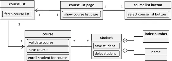
The above abstract syntax calls for appropriate concrete syntactic elements. Our metamodel introduces a special kind of structural domain representation that explicitly focuses on domain elements. It can be seen as possessing some of the key object-oriented principles: domain elements can be connected through domain element associations adorned with multiplicities. We could thus simply use UML class model notation. However, where a graphical notation is nec-essary, we propose a notation clearly distinguishing domain elements from classes. This is to stress its domain modelling (cf. ontological modelling) pur-pose. This is illustrated in Figures 6 and 7. The first Figure presents a textual description of the notion “course” with several phrases. It can be noted that the notion description contains phrases (represented by hyperlinks in the de-scription). In Figure 7 we can see a graphical notation that includes the same notion. The phrases have a notation that clearly distinguishes them from e.g. class operations.
2.3. Hyperlinking Phrases to Build Sentences
SVOSentence
PhraseHyperlink
Subj ect
PhraseHyperlink
Predicate
Phrase
NounPhrase
Phrase
VerbPhrase
HyperlinkedSentence
ConstrainedLanguageSentence
target
1 predicate
*
object 1
verbPhrase 0..1 target
1 subject
*
predicate
1 1
subject
1
1
Fig. 8.Constrained language sentence metamodel
we could organise this way the functional requirements. Through consistent use of hyperlinks we could significantly raise precision and unambiguity of such specifications. For this purpose we will thus extend the presented language to allow formulating full sentences constructed out of hyperlinks.
We have already seen that all the elements used in phrases link toTerms
in the terminology. In fact, phrases consist only of hyperlinks to specificTerms
through theTermHyperlinkconstruct. This idea is extended to use phrases as targets of hypelinking and to construct specifications as sequences of hyper-links to phrases. Now, instead of copying the same phrase in many places, we just point to its definition placed in a central domain specification. This provides consistency as every hyperlink may point at exactly one element. This is in line with the findings by Kaindl [18] which indicate that hyperlinks applied in require-ments specifications are basic facilitators of coherence. However, the approach is beneficial only with strong tool support, which we will discuss in Section 3.
The precision of system specifications is assured by using hyperlinks that link interaction flow descriptions with definitions of phrases. In textual specifica-tions, this leads to the idea of a wiki-like language. Hyperlinks can be inserted into free-form text using the notation presented in the previous section (see Fig-ure 6). They can consist of linked term names preceded by a letter with a colon (“:”) indicating the term type (“n:” for a noun (NounLink), “m:” for aModifierLink, “v:” for aVerbLink, “p:” for aPrepositionLink. Each hyperlink text is surrounded by a pair of square brackets.
Unfortunately, free (although hypelinked) text used in specifications has se-rious limitations. Namely, it is not suitable for automatic processing (e.g. transla-tion into design or code, comparison, structured editing, semantic operatransla-tions), and it can be formulated still in an unreadable way. To cater for these two prob-lems we would need to introduce much more rigour and limit the language used. We will now present such a limited language with SVO sentences. They will use phrases (or rather: hyperlinks to phrases) as their atomic “lexemes”.
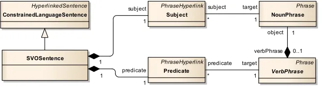
The overall structure of an SVO sentence is shown in Figure 8. It consist of
aSubjectthat points to a regular (noun-only)Phraseand aPredicatethat points
to one of the concrete subtypes ofVerbPhrase.
pro-SVO sentence
System shows course list page
Subject Predicate
Noun phrase Simple verb phrase
Noun Verb Noun
Subject Predicate
Fig. 9.Example of SVO sentence with simple verb phrase
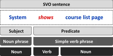
posed by Graham [15]. An example of such a sentence structure is illustrated in Figure 9. It can be seen that thePredicate of this sentence is a hyperlink to
aSimpleVerbPhrase, and theSubjecthyperlinks to aNounPhrase. These phrases
are further hyperlinked to appropriate terms in the terminology.
In a more complex case, the Predicate points to a ComplexVerbPhrase. In such situation, the sentence is extended by an additional indirect object (SVOO) allowing to express more complex behaviour involving more than one noun phrase (eg. “System adds class to course”).
2.4. Use Case Scenario – Sequence of Sentences
It can be argued that most of the observable behaviour of a software system (its application logic) can be described at the level of requirements with sen-tences presented in the previous section. For the purpose of defining system’s behaviour, RSL employs use cases as units of system’s functionality. Each use case can be detailed with one or more textual scenarios consisting of sentences in constrained natural language that links to elements of the domain model. RSL defines only one type of relationship between use cases – theinvoke rela-tionship. This relationship denotes the situation where scenarios of a use case can be invoked from within another (invoking) use case. A detailed example of notation for use cases and scenarios is shown in Figure 10.
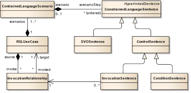
Figure 11 shows a fragment of the RSL metamodel that deals with use case scenarios. Every RSLUseCase contains at least one
ConstrainedLanguageSce-nario. Scenarios, in turn, are composed of ordered set of scenarioSteps
form-ing paths of scenario execution. Every such step is a subtype of an abstract
ConstrainedLanguageSentence: anSVOSentence,InvocationSentenceor
Condition-Sentence. The two latter sentences are special types ofControlSentence.
As it was explained above, the predicate of an SVO sentence in a scenario describes an operation that can be performed in association with some entity (eg. “fetch course list”, “save course”). The subject, in turn, indicates who per-forms the action (eg. “course manager” or “system”).
1. Course managerselectscourse list button
2. Systemfetchescourse list
3. Systemshowscourse list page
⇒invoke Add new course
1. Course manager selectsadd course button
2. Systemshowsadd new course page
3.Course managerenterscourse
4. Course manager selectssave course button
5.Systemvalidatescourse
⇒ cond: course valid
6. System savescourse
Course Manager
Show course list
Add new course «i nvoke»
6. System savescourse
Fig. 10.Concrete syntax for use case scenarios
HyperlinkedSentence ConstrainedLanguageSentence
SVOSentence ContrainedLanguageScenario
RSLUseCase ControlSentence
ConditionSentence Inv ocationSentence
Inv ocationRelationship
scenarioStep
* {ordered} scenario
0..1
scenarios 1..*
1
invoke * source 1
invoked *
target 1
0..*
1 0..*
1
Fig. 11.Use case and scenario metamodel
can be executed only if the condition is met.ConditionSentencesalways exist in sets of at least two such sentences causing alternative scenarios. The concrete notation for this type of sentence comprises the “cond” keyword followed by a single free-text word, as illustrated in Figure 10.
The invoke relationship has simple abstract syntax reflected through
theInvokeRelationshipmetaclass. What is important, every invocation
relation-ship can have several relatedInvocationSentenceswithin the invoking use case scenarios. In concrete syntax, such sentences are denoted with the “invoke” keyword, followed by the name of the invoked use case, as illustrated in Figure 10.
Re quire mentsSpe cific ation DomainSpecification
DomainElement
Re quire mentsPac kage Requirement
RS LUse Case
DomainElem ents Pack age
Notion
req uirem entsPackages *
1
1
do main Spec ificat ion
1
ne stedP acka ge
* 0.. 1
*
* 1
*
ne stedP acka ge
* 0.. 1
Fig. 12.Requirements specification metamodel
R e q ir e m e n ts sp e ci fi ca ti o
n ALU Start
(User) w ants to brow se offers
(System) show s offers brow ser
(User) uses offers brow ser
(User) selects offer
End D o m a in X v o ca b u la ry D o m a in Y v o ca b u la ry
Application Logic Unit
Domain vocabulary Use case model and
interaction description Y v o ca b u la ry
Fig. 13.Levels of application logic management
automatically transformed into design-level models and fully operational code as well.
2.5. Requirements Specification – Container for Requirements and
Notions
All the use cases and their scenarios along with linked notions are contained within a requirements specification (see RequirementsSpecification metaclass in Figure 12). It consists of RequirementsPackages that groups Requirements –
RSLUseCasesin particular. RequirementSpecificationalso includes a vocabulary
of notions used in use case scenarios. These notions are grouped in
DomainEle-mentPackageswithinDomainSpecification. The example structure of requirements
specification in the form of a project tree is shown in Figure 14.
2.6. Application Logic Extension to RSL
application logic building blocks. This extension (called RSL-AL) builds upon RSL concepts – mainly the separation of system’s dynamics description and the domain it pertains to (see Figure 13). This gives the possibility of utilizing patterns of behaviour, to apply the application logic elements at different levels of abstraction: at the level of individual interactions (described as a scenario), at the level of functional units (through use cases) and at the level of application logic units (groups of use cases). The separation between the dynamics and the domain description facilitates using similar interaction flows in different business domains, which leads to defining patterns. As core RSL is sufficient to capture requirements and basic application logic structures, further explanation of RLS-AL concepts is out of scope of this paper; for more details on the subject please refer to Ambroziewicz and ´Smiałek [2].
3.
Process and Tools
In order to evaluate the presented approach, a tooling framework was con-structed. The intent was to enable processing the models according to the no-tation and metamodel presented in the previous sections. This included sup-port for automatic transformations to design-level artifacts and the process of recovery and migration of the legacy systems to a new architectures. In the paragraphs below we explain the tooling framework based on these objectives.
3.1. Model-driven Development with ReDSeeDS
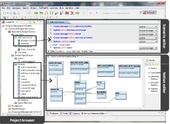
The central part of the tool chain is the ReDSeeDS tool, that implements the RSL metamodel (see sections 1 and 2). The tool offers a set of editors dedi-cated to different types of domain elements (see Figure 14, bottom-right). The central point of the tool is the use case scenario editor (as illustrated in Figure 14, top-right). It allows for writing use case scenarios in RSL. The sentences are referencing domain specification elements and marked with colours according to hyperlink types. The tool allows to manage the domain specification elements directly from the use case editor or using a typical tree-like browser (see Figure 14, left).
S
ce
n
a
rio
e
d
it
o
r
N
o
tio
n
e
d
it
o
r
Project browser
Fig. 14.Editors and browsers of the ReDSeeDS tool
The structure and notation of the target model depends on the chosen trans-formation profile as shown in Figure 16. Currently “RSL to UML” and “RSL to Java” transformation profiles are ready to use and “RSL to SoaML” is planned. The “RSL to UML” transformation profile (see work by ´Smiałek [34]) implements the MDA concepts (according to [9]) with the requirements specification as the CIM (Computation Independent Model), 4-layer solution architecture as the PIM (Platform Independent Model) and detailed design based on abstract factory in Java as the PSM (Platform Specific Model) [5]. The target models also contains sequence diagrams describing the behaviour based on use case scenarios. All messages exchanged in sequence diagrams are generated as operations in the corresponding interfaces thus keeping the target model coherent.
ReDSeeDS Framework
MOLA transformation engine
RSL model
User requirements
RSL Editor
Target models + code
1
2
3
Fig. 15.Model-driven forward engineering with ReDSeeDS
RSL to Java
Component architecture model in UML
Design model based on
Abstract Factory pattern
Java application specific design model in UML
Runnable application
code in Java Code skeleton
in an object-oriented language RSL to
UML
RSL model
model in UML
in Java
SOA model in SoaML
Specific cloud platform model RSL to
SOA
Fig. 16.Transforming RSL-AL model into different target models
18 presents a small fragment of application logic code generated automatically from the model in Figure 10. As it can be seen, all the “user” sentences (1, 3 and 5) were transformed into operations in the presenter classes. Furthermore, the “system” sentences (2, 4 and 6) were transformed into operation calls to appropriate “view” (denoted by “v”) or “model” (denoted by “m”) objects. The re-sulting code can be fully operational in regard to the application logic, i.e. it can fully control all the flows of user-system interaction. What is important, the code can also contain decisions (“if” statements) that control the interaction flow de-pending on the user decisions or the current system state. Such decisions can be generated on the basis of alternative scenarios, but a detailed discussion is out of scope of this paper. A more detailed description of use case scenario translational semantics can be found in [37].
CAddNew Course
_SelectsAddNewCourseOption() : void
_SelectsAddNewCourseOption(invokingUC :IInvoke) : void SelectsOK(pCourse :XCourse) : void
SelectsOK_2() : void
CShow Ow nedCourseList
_SelectsShowCourseListOption() : void SelectsOK() : void
invokeAddCourse() : void invokeEditCourse() : void returnInvokeResult(res :int) : void
JFrame
VCourseForm
displays(aCourse :XCourse) : void
JFrame
VCourseListForm
shows(aCourseList :XCourseList) : void
JFrame
VErrorMessage
shows() : void
vCourseForm cAddNewCourse cAddNewCourse vErrorMessage cShowOwnedCourseList vCourseListForm P r e s e n te r V ie w MCourse
fetches(aCourse :XCourse) : void getResult() : int
saves(aCourse :XCourse) : void validates(aCourse :XCourse) : void
MCourseList
builds(aCourseList :XCourseList, aTeacher :XTeacher) : void getResult() : int
returnInvokeResult(res :int) : void cAddNewCourse mCourse cAddNewCourse cShowOwnedCourseList cShowOwnedCourseList mCourseList M o d e l
Fig. 17.Fragment of the Java application design model generated with the RSL to Java transformation
into SoaML UML are expected to be similar. The output model of both groups of transformations is an UML-based logical system design at different levels of abstraction, relevant to the structure of the source requirements specifica-tion (use cases, nospecifica-tions and packages). The “RSL to SoaML” transformaspecifica-tion is expected to generate the structured model of services constructed with stereo-typed packages, components, interfaces and classes.
3.2. Recovery and Migration of Legacy System Essence with TALE
The recovery and migration process outline, supported by the tool-chain, is pre-sented in the Figure 19. The main objectives of the process are recovery of the system essence and migration of application logic information from the existing systems, with an intermediate step of storing the application logic information using the RSL metamodel and its RSL-AL extension.
classVCourseForm { ...
JButton btnSaveCourse = newJButton(„Save course"); btnSaveCourse.addActionListener (newActionListener() {
public voidactionPerformed(ActionEvent evt) {
... cAddCourseList.SelectsSaveCourseButton(course); } }); ... }
classCAddNewCourse {
...
public voidSelectSaveCourseButton(XCourse course) {
intres = 0;
res = mCourse.validates(course);
if(res == 0 /*course valid*/) { mCourse.saves(course);
} else if(res == 1 /*course invalid*/) {
vErrorMessage= newVErrorMessage(); vErrorMessage.shows();
} } ...
Fig. 18. Fragment of the code generated automatically from Java application design model Legacy system GUI-ripping tool ReDSeeDS Framework R e co v e ry 1 2 MOLA transformation engine Refined RSL model Recovered RSL model RSL Editor TALE XML scripts R e co v e ry M ig ra ti o n 2 3 4 Target models + code 5
Fig. 19.Overview of the recovery and migration process and tools
interaction is illustrated in Figure 20a. This flow of event concerns functionality of searching a client (in Polish: Wyszukiwanie klienta) in our case study legacy banking system. During this, the GUI-ripping tool records the flows of interaction representing the system’s application logic.
In our evaluation, for GUI-ripping we have used a commercial test manage-ment tool (Rational Functional Tester,www.ibm.com/software/awdtools/ tester/functional/). However, any tool allowing for interaction recording to some form of structured text files can be integrated with our software. The tool we used, records sequences of interactions into XML-based scripts (see 2 in the process outline in Figure 19).
a
b
c
Fig. 20.An example of GUI interaction (a), the automatically recovered RSL-AL model (b) and the manually refined final model (c)
sentences. Figure 20b shows an automatically extracted scenario representing the interaction illustrated in Figure 20a. All the extracted scenarios are attached to use cases, which are grouped within the “Functional Requirements” package forming the recovered model (see the project tree in Figure 20b).
displayed to enter personal data (such as first name, last name, PESEL num-ber, etc. – see the “Osoba fizyczna” tab in Figure 20a), a composite notion for “Osoba fizyczna data” is created. Such notion contains attributes for every field filled on the form, instead of a number of unrelated notions coresponding to these fields. This reduces the unnecessary complexity of the recovered model by minimizing the amount of simple notions created from the GUI recordings.
The recovered initial model, thanks to the characteristics of the RSL lan-guage, is easily understandable to people (even those barely knowledgeable of the original system internals) thus giving the possibility of its easy exten-sion and modification. This can be made in the ReDSeeDS tool. First of all, some modifications are needed because not all of the application logic infor-mation can be automatically retrieved from the recording scripts. This includes sentences that control flow of scenario execution (conditions and invoke
sentences) and sentences expressing internal system operations (eg. calls to business logic operations), such as “System verifies data”, “System stores in-formation”, “System deletes item from item list” etc. Also the domain vocabu-lary usually needs renaming some of the automatically recovered notions. The generated use case specification can also be subject to manual modifications and additions. Changes can be done to cater the migrated system for new or changed functionality or just to optimize some scenario flows, eg. by applying standard application logic patterns [2]. Also, we need to reorganise the model according to the needs of the selected transformation rules. Figure 20c shows the recovered model after refinements.
The refined model (see 4 in the process outline in Figure 19) contains both the still relevant “legacy” specifications and the “new” ones. This constitutes the “essence” of the application logic. We can now use this essence to migrate to a new system design. The migration phase is realised as described in the previous section (as denoted in Figure 19).
4.
Evaluation
express-ing requirements. While workexpress-ing within such a “discover notions – write struc-tured sentences” framework, the analysts are encouraged to be acquainted with software system’s environment and are stimulated to write precise, clearly for-mulated requirements statements.
Further studies, in order to validate the ReDSeeDS model-driven software development approach, were performed with students attending the “Model Driven Software Engineering” course at the Warsaw University of Technology. The students were instructed on RSL constructs and had previously gained knowledge about constructing Model-View-Controler/Presenter style systems, using UML and Java. During the classes, they were formed into 8 groups con-sisting of 3-4 students each. All the groups were assigned a ready use case model of a Campus Management System, containing 12 use cases with invoke relationships. The first assignment consisted in writing scenarios for the use cases. Four groups wrote the scenarios using the ReDSeeDS tool, while four other groups used a structured use case editor built into Enterprise Architect (EA). The EA editor did not enforce any syntax for the story sentences, although allowed for almost identical structure of scenarios with conditions and notation for alternatives. Moreover, it allowed for hyperlinking of sentence parts to other model elements and the students were asked to introduce links to classes that represented concepts.
The students had 4 hours (2 lab sessions) to write their scenarios and were asked to write them only during the classes. All the groups managed to write good quality scenarios for all the assigned use cases. There were no signif-icant differences between the groups using EA and ReDSeeDS. The groups produced from 121 to 159 scenario sentences (more than 10 sentences per use case) of all types. The average values are illustrated in Figure 21. Based on this, the groups were asked to implement their systems in Java having 10 hours (5 lab sessions). Each scenario sentence was treated as complete if the system managed to pass appropriate data between layers and output “debug” messages. Two of the groups used the RSL to Java transformation, two groups used the standard RSL to UML transformation. The remaining four groups per-formed manual translation into UML and then code generation within the EA. The first two groups of students managed to implement almost half of the func-tionality, where on average 68 out of 141 sentences were implemented. It has to be noted that these two groups had extended acceptance criteria where the “de-bug” messages for the presentation layer were substituted with Swing-style GUI forms. The last four groups of students managed to implement 21 sentences on average. The groups that used the standard RSL to UML transformation per-formed somewhat better with the average of 28 sentences. A visual comparison is given in Figure 21.
0 20 40 60 80 100 120 140 160
ReDSeeDS RSL to Java (2 groups)
ReDSeeDS RSL to UML
Average sentences written
ReDSeeDS RSL to UML (2 groups)
Enterprise Architect (4 groups)
Average sentences implemented
Fig. 21.Student group performance during the evaluation experiment
team leaders chose their group members during a “draft” session thus balanc-ing qualifications between teams. Second, the results could be influenced by lack of necessary proficiency in software design by the groups not using the fully automatic translation. This threat is to some extent reduced by the fact that all the students had previous experience in designing non-trivial three-tier de-sign models during a “Software Dede-sign” course. Third, the tooling environment could influence the students’ performance. The EA system was stable and no problems were reported, but the ReDSeeDS system caused some issues due to its prototypical characteristics. In order to assess the last two threats, certain additional (“anecdotal”) information from the students was collected. This con-firms that the students from the “EA” and “RSL to UML” groups had problems in designing the systems (or implementing the application logic code within the generated design) by hand and this took most of their implementation time. The automatically generated code gave significant guidance thus improving the performance of the respective groups. The students using ReDSeeDS have re-ported several problems with using the system, although this did not interfere significantly with their flow of work.
5.
Conclusion and Future Work
to write by inexperienced developers (analysts) and even the end-users. This can be done using any tool that allows for hyperlink management. This promi-nently includes wiki systems, but also some CASE tools enable this (see e.g. the scenario editor of Enterprise Architect,www.sparxsystems.com).
Writing scenarios hyperlinked to a central vocabulary gives important ele-ment of coherence to specifications. However, in order to be able to perform automatic transformations or semantic-based matching [40], we need a tool that implements the presented (or analogous) metamodel. In the current work we have shown that it is also possible to use such a tool as a repository for es-sential application logic recovered from legacy systems. This repository gives an additional advantage of generating code directly from high-level scenarios. This includes not only the code structure (classes, method signatures) but also the dynamics (method bodies) for the application logic layer.
It can be noted that the presented results can be extended in the direction of creating a more expressive language at the “essential” level. It has to be stressed that the language is not meant for data processing. Thus, it will not possess typical data-processing constructs like loops or variables. Instead, it concentrates on capturing application logic, where loops are implicit through repeated system-user interaction. The currently ongoing work focuses on im-proving utilization of application logic patterns as proposed by Ambroziewicz [2]. The presented language can be used as a pattern language where the noun and verb phrases can be abstracted from a particular problem domain. The pat-terns can operate on a generalised domain and then can be instantiated for a specific domain.
Future work will also include extending the TALE tool to be able to recover scenarios combined into use cases on the basis of analysis of GUI-ripping re-sults. It will also consist in extending the language into a language fully capable of performing “programming” at the level of essential application logic. The goal is to move much of such programming activity to a significantly higher level of abstraction than currently. This way, the application logic programming can be-come accessible even to the end-users. It has to be noted that this language would not yet capture all the essence of a software system functionality. The domain logic will not be expressed in any way. The domain statements would indicate the necessary domain functionality (data processing algorithms etc.), but not define this functionality.
modifier
noun
verb
modifier
noun
preposition
modifier
noun
Finally, it has to be noted that the SVO grammar is a kind of controlled language with formal grammar as presented in Figure 22 (see also e.g. work by Fuchs et al. [14] or Sleator and Temperley [31]). In this grammar, subclasses ofTermmetaclass in Figure 3 are terminal symbols. We can thus use a simple analyzer based on a finite state machine to parse SVO sentences.
The grammar as such does have some difficulties with reflecting different natural languages. Some heavily inflected languages, like Polish, need suffixes and prefixes for words, even in sentences with similar structure and meaning. Another problem is that some languages (e.g. German, Turkish) allow for differ-ent order of words in a sdiffer-entence. This can be solved by adding, for example, attributes to sentence classes, indicating word order or language used for this sentence. Nonetheless handling of multi-language specifications is a very inter-esting challenge for future research and should be investigated further.
Acknowledgments.This research has been carried out in the REMICS project (http:
//www.remics.eu) and partially funded by the EU (ICT-257793 under the 7th
Frame-work Programme).
References
1. Resource Description Framework (RDF),http://www.w3.org/RDF/
2. Ambroziewicz, A., ´Smiałek, M.: Application logic patterns – reusable elements of user-system interaction. In: Model Driven Engineering Languages and Systems, Lecture Notes in Computer Science, vol. 6394, pp. 241–255 (2010)
3. Bj ˆorner, D.: Software Engineering 3: Domains, Requirements, and Software Design. Texts in Theoretical Computer Science. An EATCS Series, Springer (2006) 4. Bj ˆorner, D.: R ˆole of domain engineering in software development. why current
re-quirements engineering is flawed! Lecture Notes in Computer Science 5947, 2–34 (2010), PSI 2009
5. Bojarski, J., Straszak, T., Ambroziewicz, A., Nowakowski, W.: Transition from pre-cisely defined requirements into draft architecture as an MDA realisation. In: Smiałek, M., Mukasa, K., Nick, M., Falb, J. (eds.) Model Reuse Strategies Work-shop, Beijing. pp. 35–42 (2008)
6. Brooks, F.P.: No silver bullet: Essence and accidents of software engineering. IEEE Computer 20(4), 10–19 (April 1987)
7. Chan, C.W.: Knowledge and software modeling using UML. Software and Systems Modeling 3(4), 294–302 (2004)
8. Dixon, R.M.: A new approach to English Grammar, on semantic principles. Oxford University Press (1991)
9. Elvesaeter, B., Berre, A.J., Sadovykh, A.: Specifying services using the service oriented architecture modeling language (SoaML) - a baseline for specification of cloud-based services. In: Leymann, F., Ivanov, I., van Sinderen, M., Shishkov, B. (eds.) CLOSER. pp. 276–285. SciTePress (2011)
10. Evans, E.: Domain Driven Design: Tackling Complexity in the Heart of Software. Addison-Wesley (2004)
12. Fellbaum, C. (ed.): WordNet: An Electronic Lexical Database. MIT Press (1998) 13. Fowler, M.: Patterns of Enterprise Application Architecture. Addison-Wesley
Long-man Publishing Co., Inc., Boston, MA, USA (2002)
14. Fuchs, N.E., H ¨ofler, S., Kaljurand, K., Rinaldi, F., Schneider, G.: Attempto controlled english: A knowledge representation language readable by humans and machines. Lecture Notes in Computer Science 3564, 213–250 (2005)
15. Graham, I.M.: Task scripts, use cases and scenarios in object-oriented analysis. Object-Oriented Systems 3(3), 123–142 (1996)
16. Iglesias, C.A., Fern ´andez-Villamor, J.I., Pozo, D., Garulli, L., Garc´ıa, B.: Combining domain-driven design and mashups for service development. In: Dustdar, S., Li, F. (eds.) Service Engineering, pp. 171–200. Springer Vienna (2011)
17. Jedlitschka, A., Mukasa, K.S., Weber, S.: Case reuse verification and validation report. Project Deliverable D6.2, ReDSeeDS Project (2009), www.redseeds.eu 18. Kaindl, H.: Using hypertext for semiformal representation in requirements
engineer-ing practice. The New Review of Hypermedia and Multimedia 2, 149–173 (1996) 19. Kaindl, H., ´Smiałek, M., , Wagner, P., et al.: Requirements specification language
definition. Project Deliverable D2.4.2, ReDSeeDS Project (2009), www.redseeds.eu 20. Kaindl, H., Snaprud, M.: Hypertext and structured object representation: A unify-ing view. In: Proceedunify-ings of the Third ACM Conference on Hypertext. pp. 345–358 (1991)
21. Kalnins, A., Barzdins, J., Celms, E.: Model transformation language MOLA. Lecture Notes in Computer Science 3599, 14–28 (2004), MDAFA’04
22. Kleppe, A.G., Warmer, J.B., W, B.: MDA Explained, The Model Driven Architecture: Practice and Promise. Addison-Wesley (2003)
23. Kleppe, A.: Software Language Engineering: Creating Domain-Specific Languages Using Metamodels. Addison-Wesley Professional, 1 edn. (2008)
24. Koll ´ar, J., Vagaˇc, M.: Aspect-oriented approach to metamodel abstraction. COM-PUTING AND INFORMATICS 31(5), 983–1002 (2012), http://www.cai.sk/ ojs/index.php/cai/article/view/1184
25. Memon, A.M., Banerjee, I., Nagarajan, A.: GUI ripping: Reverse engineering of graphical user interfaces for testing. In: Proceedings of the 10th Working Confer-ence on Reverse Engineering. pp. 260–269 (2003)
26. Miller, J., Mukerji, J. (eds.): MDA Guide Version 1.0.1, omg/03-06-01. Object Man-agement Group (2003)
27. Object Management Group: Meta Object Facility Core Specification, version 2.0, formal/2006-01-01 (2006)
28. Object Management Group: Service Oriented Architecture Modeling Language (SoaML) Specification, version 1.0, formal/2012-03-01 (2012)
29. P ´erez-Castillo, R., de Guzm ´an, I.G.R., Piattini, M.: Knowledge Discovery Metamodel-ISO/IEC 19506: A standard to modernize legacy systems. Comput. Stand. Interfaces 33(6), 519–532 (2011)
30. Potel, M.: MVP: Model-View-Presenter the taligent programming model for C++ and Java. Taligent Inc (1996)
31. Sleator, D.D.K., Temperley, D.: Parsing english with a link grammar. Tech. Rep. CMU-CS-91-196, Department of Computer Science, Carnegie Mellon University (1991)
32. ´Smiałek, M.: Accommodating informality with necessary precision in use case sce-narios. Journal of Object Technology 4(6), 59–67 (2005)
34. ´Smiałek, M., Ambroziewicz, A., Bojarski, J., Nowakowski, W., Straszak, T.: Introduc-ing a unified requirements specification language. In: Proc. CEE-SET’2007, Soft-ware Engineering in Progress. pp. 172–183. Nakom (2007)
35. Smialek, M., Ambroziewicz, A., Nowakowski, W., Straszak, T., Bojarski, J.: Using structured grammar domain models to capture software system essence. In: FedC-SIS. pp. 1349–1356 (2012)
36. ´Smiałek, M., Bojarski, J., Nowakowski, W., Straszak, T.: Writing coherent user sto-ries with tool support. Lecture Notes in Computer Science 3556, 247–250 (2005), XP’05
37. Smialek, M., Jarzebowski, N., Nowakowski, W.: Runtime semantics of use case stories. In: VL/HCC. pp. 159–162 (2012)
38. Vagaˇc, M., Koll ´ar, J.: Improving program comprehension by automatic metamodel abstraction. Computer Science and Information Systems 9(1), 235–247 (2012) 39. ˇSimko, V., Hn ˇetynka, P., Bureˇs, T.: From textual use-cases to component-based
ap-plications. Studies in Computational Intelligence 295, 23–37 (2010)
40. Wolter, K., ´Smiałek, M., Hotz, L., Knab, S., Bojarski, J., Nowakowski, W.: Map-ping MOF-based requirements representations to ontologies for software reuse. In: CEUR Workshop Proceedings (TWOMDE’09). vol. 531 (2009)
Wiktor Nowakowski is currently pursuing his PhD at the Institute of Theory
of Electrical Engineering, Measurement and Information Systems at the War-saw University of Technology. His main area of research interest is in Require-ments Engineering, Model-Driven Software Development, metamodeling and Software Language Engineering. He is also engaged in teaching in these areas. Wiktor has an extensive experience working on small- to large-scale projects in roles covering all stages of the software development life cycle.
Michał ´Smiałekis a Professor of Computer Science at the Warsaw University
of Technology. He lectures mainly in the area of Model-Driven Software Devel-opment both in the academia and for software professionals. Prof. ´Smiałek has also over 20 years of experience in software development as a programmer, analyst, process engineer and project manager. He has published over 70 peer reviewed papers and a popular book on UML. Michał ´Smiałek leads the SMoG research group that is involved in research and international projects in the area of Model-Driven Requirements Engineering.
Albert Ambroziewiczis professionally engaged in software engineering, mostly
in topics related to modeling and metamodeling. He is interested in practical im-plementations of solutions connected with Model Driven Architecture issues, as well as CASE tools support for industrial usage of UML. Currently he partici-pates in the REMICS project. In the past he took part in several commercial projects, mostly in the fields of enterprise architecture, analysis, R&D and pro-totyping.
Tomasz Straszak is a researcher interested in software modeling,
Soft-ware Modeling Group at the Warsaw Unieversity of Technology. He gained pro-fessional experience in telco and banking sectors working as a system/business analyst, software and solution architect and programmer.